![]()
Delta Printer Hardware
The delta 3D printer design, despite the radically different axes arrangement, uses the same basic hardware as a Cartesian printer. For example, there isn’t anything special about the stepper motors, electronics board,1 or even the hot end. The differences are in how the axes are arranged (all three are vertical), and that the print bed is typically round (older designs use square or rectangular build surfaces) and the frame is typically triangular. These qualities alone are what give the delta printer its unique vertical form with a small footprint.
![]() Note Internet lore
2 defines delta printers by their triangular or prismatic frame shape. However, not all delta printers have that shape. Some have cylindrical frames that resemble a cylinder more than a prism, and early designs employed rectangular frames.
Note Internet lore
2 defines delta printers by their triangular or prismatic frame shape. However, not all delta printers have that shape. Some have cylindrical frames that resemble a cylinder more than a prism, and early designs employed rectangular frames.
In this chapter, you discover how a delta printer works; how delta printers are constructed, including all the components for the frame, axes, electronics; and more. You will also look at a few variants of delta printer designs.
While all delta printer designs share the same axes arrangement, they can vary greatly in how they are constructed. For example, the frame can range from printed components attached to wood pieces, entire frames made from wood, frames that incorporate aluminum extrusion uprights attached to wood or printed parts, as well as smooth rods for the towers.
Before you learn more about the hardware, let’s see how a delta printer works. That is, how it can resolve positioning the hot end to a specific location within the build volume.
Anatomy of a Delta Printer
In this section, I explore the components that make up a delta printer from the perspective of how the components work as part of the whole. I will discuss the hardware that makes up these components in the next section. Knowing how the components work will give a much better insight on how the printer is constructed. Not only will this help you understand your printer better, but it can also help you should you decide to build your own delta printer.
I begin with the axes arrangement and how the printer can position the hot end within the build volume. Following that, you learn about the extruder, electronics, and build plate. To get started, let’s review the names of the various components that make up a delta printer. Figure 2-1 shows a mock-up of a typical delta printer with the components labeled. This image depicts the major components of the delta design. This is not a complete or even dimensionally accurate drawing, but it does illuminate the components that I will discuss.

Figure 2-1. Anatomy of a delta printer
Starting from the lower-left corner, you see the following:
- Extruder: Also called the cold end. Responsible for feeding the filament to the hot end.
- Build plate: Where the printed parts are formed. Some build plates are heated.
- Axes: Arranged vertically and labeled counter-clockwise as X, Y, and Z.
- Carriage: Attaches to the axis mechanism and provides a mount point for the delta arms.
- Effector: The base where the hot end is mounted.
- Delta arms: Attaches to the carriage and the effector using a pair of parallel arms.
- Hot end: A special heater that heats the nozzle for melting (glassing) the filament for extrusion.
Now that you have the terminology down, let’s see how the axis mechanisms work.
Axes
Each axis is mounted so that travel is in the vertical direction. A carriage is mounted on the axis movement and forms one side of a link of parallel arms that connect the carriage to the effector. Thus, as the axis moves up and down, the carriage moves along with it.
Recall that the combination of delta arms, effector, and axis movement forms a right triangle, as shown in Figure 2-2. Here you see that the delta arms forms the hypotenuse of a right triangle, formed by the vertical axis, and an imaginary line drawn from the axis to the effector.

Figure 2-2. Delta geometry
Notice that there are two offsets you must also consider. There is a small distance from the center of the axis movement to the mount point for the delta arms on the carriage. There is also a short distance, as measured from the delta arm mount point on the effector to the center of the nozzle on the hot end. Thus, any calculation must also consider these measurements when positioning the effector.
![]() Note Figure 2-2 shows only one axis, but the measurements and angles defined are the same on all three axes.
Note Figure 2-2 shows only one axis, but the measurements and angles defined are the same on all three axes.
So how does the printer (the firmware) figure out where to position the effector using this data? It’s a clever use of trigonometric equations made easier given the axis, delta arms, and effector form a right triangle.3 With this information you can calculate how much to move the one side (B) in order to move the effector (side A). In this case, you know the hypotenuse is always the same length (the delta arms), so to calculate a movement you use the formula for calculating the sides of a right triangle by using the sum of squares.
But this is only half of the calculations needed. You also need to know where each tower is located in relation to one another. If you envision looking down from the top of the printer, the axes are located as shown in Figure 2-3. Notice the angles formed by the imaginary triangles superimposed over the build plate. You can simplify the math a bit if you consider that the delta arms form a parallelogram, and thus you need only calculate the triangle representing the center of each pair of arms.
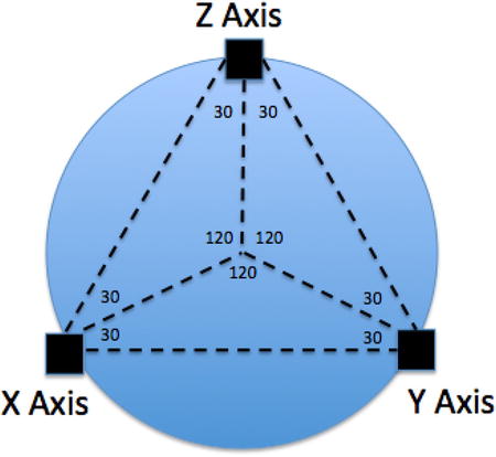
Figure 2-3. Location of towers
Notice that the triangles formed allow you to know where the towers are in relation to one another. In fact, once you know the radius of the circle formed from intersecting with each tower (also called delta radius), you can calculate the location of each tower using sine and cosine functions. Listing 2-1 is an excerpt from the Marlin firmware (located in Configuration.h).
Here you see that the Marlin firmware uses the Y tower as the starting point for the calculation (an arbitrary assignment, as the calculations would be the same for any origin).
Now that you know where each tower is located in relation to one another, you can calculate any movements by using the location of the tower, the original position of each axis, and the Cartesian location of where you want to move. Listing 2-2 shows the calculations from the Marlin firmware (located in Marlin_main.cpp).
As you can see, the firmware calculates solutions for all three axes. In this way, the printer moves all three axes simultaneously to reposition the hot end. Pretty cool, eh?
There is a little bit more involved in calculating the position for each axis. If the printer supports auto bed leveling (Z-probing), there are additional calculations performed after these to refine the positions. Not to mention the adjustments made for the carriage, effector, and hot-end offsets. However, for our discussion, consider these calculations as those responsible for positioning the effector.
Let’s look at an example of the calculations. In this example, you position the printer to the Cartesian values [0,0,0]4 and you want to move the effector to position [–40,20,15]. Furthermore, you want to see how the preceding calculations resolve to movements of the three axes. I use a Kossel Pro printer as an example, but you can use your own delta printer. However, if you are in the process of building your printer, or if you have not configured or calibrated the printer, you may want to read the next two chapters and then return to this exercise; or simply follow along as I demonstrate the math.
Begin by moving the hot end to the bed center position. You can use your printer controller software or LCD to do this. Next, use a small section of masking or blue painter’s tape and mark the location of each carriage on the towers. Figure 2-4 shows an example of marking the X tower on my printer. Be sure to position the tape so that it does not interfere with axis movement.

Figure 2-4. Marking the carriage position
![]() Note While not purely scientific, the following will demonstrate how these calculations resolve the position of each axis to effect movement within the build volume.
Note While not purely scientific, the following will demonstrate how these calculations resolve the position of each axis to effect movement within the build volume.
Next, move the effector to the left 40mm (X = –40) and forward 20mm (Y = 20), and then raise the effector 15mm (Z = 15). Once in position, measure the distance that each axis has moved. Don’t worry about being accurate because this isn’t a scientific test, rather a demonstration. Figure 2-5 shows how I measured one of the axes.
TOWER AND AXIS NAMING
In a Cartesian printer, each axis moves separately in a single plane. Thus, it is correct to simply refer to each movement of the axis in the X, Y, or Z direction. However, in the delta coordinate system, each axis is oriented vertically, and thus the X and Y axes mechanisms do not move in the same plane. Only the Z tower can be considered in the same plane. But that is not correct either. Recall that it requires movement from all three axes to effect a movement in the X, Y, and Z planes.
Thus, you refer to each axis movement as A, B, and C or alpha, beta, and gamma corresponding to the X, Y, and Z towers. You may find some delta literature that refers to these as the A, B, and C towers. When you measure the axis movement, not the position of the effector, you refer to the axis movement as A, B, and C.
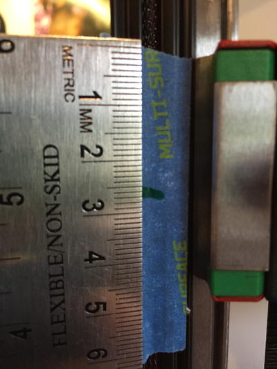
Figure 2-5. Measuring axis movement
When I measured my towers, I found the following:
X Tower (A) = 25.5mm
Y Tower (B) = -17mm
Z Tower (C) = 23mm
Notice the signs I used. When the axis moves “up,” it is moving in the positive direction. Thus, if the carriage is located above your mark, you measure that as a positive value; when the carriage is below the mark, you measure it as a negative value.
Now let’s do the math. Rather than solve the equations by hand, I wrote a short Python script to perform the calculations. Listing 2-3 shows the code I created. You can download source code for this book from apress.com/9781484211748?gtmf=s. I simplify the code a bit to make it easier to read, but the calculations are exactly the same as the preceding ones.
Notice that I copied in a number of definitions for various values. I retrieved these directly from the firmware (located in Configuration.h), converting them to Python (a minor syntax difference). If you want to do this for your printer, you will have to change these defaults to match. You will see where these values are located in Chapter 3.5
To use this code, you execute it passing in six values. The first three are the starting position, [0,0,0], the next three are the ending position, [–40,20,15]. The code then calculates the delta values for each and then calculates the difference, producing the distance each axis must travel to reposition the effector (hot end). Listing 2-4 shows the results of running this script.
Notice here the values produced for X, Y, and Z. Recall that I measured values 25.5, -17, and 23. Clearly, the calculations worked because the measured values were approximately the same as those shown in the output. Try it yourself by choosing other values.
If the code and calculations described here are still a mystery, don’t worry because all these are built into the firmware, and thankfully not something you have to calculate yourself. However, as you will see in Chapter 5, it is good to know how the printer calculates positions so that you can move the hot end (effector) to a position located at the base of each tower. This is needed for calibrating the towers and endstop positions.
Now that you understand how a delta printer uses three vertical-axis mechanisms to resolve any X,Y,Z position within the build volume, let’s look at the hardware components that make all this magic work.
Hardware Components
The hardware and materials used to construct delta printers varies greatly, despite some fundamental concepts. You can find printers that are made from wood, others constructed with major components made from plastic, and some that are constructed from a sturdy metal frame, but most will be made using a combination of these materials. Not only do the materials used in constructing the frame vary, so do the mechanisms used to move the print head and extrude filament, but not nearly as much as the frame.
A delta printer is a special type of machine called a robot. You may think of robots as anthropomorphic devices that hobble around bleeping and blinking various lights (or bashing each other to scrap in an extremely geeky contest), but not all robots have legs, wheels, or other forms of mobility. Indeed, according to Wikipedia, a robot is “a mechanical or virtual agent, usually an electromechanical machine that is guided by a computer program or electronic circuitry”. As you will see, delta printers fit that description quite well.
The following sections introduce the hardware as follows: the hardware used in extruding plastic (extruder or cold end and the hot end), delta arms, axes, types of electric motors used, build platform, electronics, and finally, the frame. Each section describes some of the variants you can expect to find, and some of the trade-offs for certain options.
Extruder
The extruder is the component that controls the amount of plastic used to build the object. On a delta printer, the extruder is normally mounted in a fixed position on the frame6 (also called the cold end) and connected to the hot end via a Bowden tube. I have seen at least one delta printer that mounted the extruder on the effector, but that design is an exception because the goal is normally to reduce the weight of the effector, delta arms, and hot end to allow for faster movement.
When the hot end is at the correct temperature for the filament used, the extruder pushes the filament through the Bowden tube, and as the effector is moved, the plastic is extruded through the nozzle.
Figure 2-6 shows a photo of a 3D printer extruder assembly. The filament is fed into the top of the extruder. This is a direct-drive extruder that does not use any gears (although geared stepper motors can be used if you need a different ratio). Thus, there is a stepper motor attached to the extruder that turns the filament drive gear. This is called an EZStruder from SeeMeCNC (http://seemecnc.com/collections/parts-accesories/products/ezstruder-cold-end-kit).
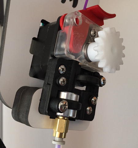
Figure 2-6. Extruder assembly (EZStruder by SeeMeCNC)
Figure 2-7 shows an example of a different extruder. This is an Airtripper extruder (thingiverse.com/thing:126778), which is a very popular choice for 3D printer builders.
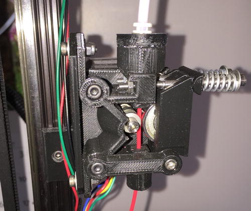
Figure 2-7. Extruder assembly mounted on a Mini Kossel
Figure 2-8 shows an example of a filament drive gear. Notice the splines or grooves machined into the pulley. These help the pulley grip the filament. Indeed, as you will learn in Chapters 6 and 7, these grooves can become clogged with filament, causing the extruder to slip. This is a common source of problems and a frequent maintenance task.

Figure 2-8. Filament drive gear
In almost all cases, extruders use a tension mechanism to help the extruder grip the filament. For example, the EZStruder uses a spring-loaded arm and the Airtripper extruder uses a door with an idler pulley (in this case, a small sealed bearing). The extruder shown in Figure 2-8 is a modification of the original Airtripper design that uses springs instead of a flexible hose to keep tension on the drive pulley.
Now that you have an idea of how the extruder heats and extrudes plastic to form objects, let’s talk briefly about where all that plastic goes—the hot end!
Hot End
The hot end, if you recall, is responsible for accepting the filament fed from the extruder body, and heating it to its melting point. You can see one of the latest hot-end upgrades for 3D printers in Figure 2-9. This is an E3D v6 all-metal hot end (http://e3d-online.com/E3D-v6/Full-Kit).
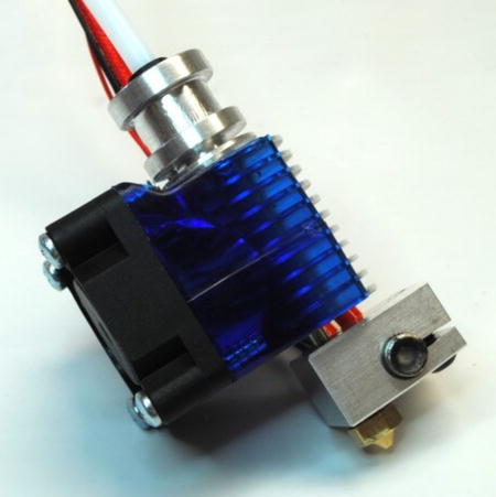
Figure 2-9. E3E v6 hot end (courtesy of MatterHackers)7
This hot end can be used with higher heat ranges and provides a very good extrusion rate for PLA, ABS, and other filaments. Notice the fan and shroud. This hot end, like most all-metal hot ends, must have a fan blowing across the cooling fins at all times. That is, the fan is always running.
There are dozens of hot end designs available for 3D printers. This may seem like an exaggeration, but it isn’t. My research revealed several sites listing 10 or even 20 designs. The site that seems most complete is at https://sites.google.com/site/3dprinterlist/home/hot-ends. You will find links to details about each of the more than 50 hot ends listed—and this list is a bit out of date because there are even more available.
With so many hot-end designs, how do you know which one to choose or even which one is best for your printer, filament, and object design choices? Fortunately, most hot-end designs can be loosely categorized by their construction into two types: all metal and PEEK body with PTFE (polytetrafluoroethylene) liner. There are some exceptions, like an all-metal design with a PTFE liner; but in general, they either are made from various metals, such as brass for the nozzle, aluminum for the body (with cooling fins), and stainless steel for the heat barrier, or use a liner of some sort. The most popular PEEK variant is called a J-head hot end. Most delta printers come with either an all-metal hot end or a J-head hot end.
If you have a choice of hot ends, you may want to consider using an all-metal hot end. An all-metal hot end offers several advantages, including the following:
- A higher operating temperature range that allows you to use a wider variety of filament.
- The print quality is generally cleaner given that the fins allow a smaller heat zone and thus better retraction and less oozing.
- Most have fewer parts, and therefore are easier to maintain.
Now let’s revisit the axis movement and discover the hardware used to raise and lower each axis.
Axis Movement
A 3D printer gets its name from the number of planes it uses to construct objects. Technically, the axes movement is called a three-dimensional Cartesian coordinate system. Recall that the delta printer has its X axis oriented left to right, the Y axis front to back, and of course, the Z axis up and down.
Since the origin is in the center, as the printer moves the X axis to the left, its position is recorded as a negative value; and as it moves to the right, the position is increased, and when it is to the right of the origin, the values are positive. Similarly, the Y axis is positive toward the rear of the build plate and negative toward the front. Figure 2-10 depicts a cube that illustrates the planes of movement with a cylinder, representing the build volume of a delta printer superimposed. Notice that in the drawing, the end points of the axes are labeled with a plus or minus sign. This is representative of how the printer moves.
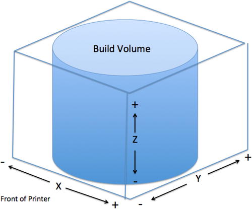
Figure 2-10. Axes movement and orientation
So how does the printer move the axis and how does it work? This is an area that can vary among delta printers, but fortunately there are only a few different mechanisms. Some use smooth rods with bearings to support the mechanical parts of the axis, whereas others use wheels running in tracks. Bearings can be made from plastic, oil-infused bronze, or special ball bearings (called linear bearings). Still others use a special rail with recirculating ball bearings. This is called a linear rail. Movement of the axis is accomplished with an electric motor and either a belt or a cable. I will explain each example mechanism in the forthcoming sections.
Whichever mechanism is used to move the axis, the geometry of that mechanism must be known and entered into the firmware. For example, the size of the drive pulley (the one mounted on the electric motor) and the number of teeth per millimeter of the belt are critical for determining how far the firmware must turn the motor to move the axis a fraction of a millimeter.
Smooth Rods
The earliest form of vertical delta printer axis mechanisms used a pair of smooth rails with linear roller bearings, brass bushings, or even bushings made from Nylon or PLA (and thus printed). Figure 2-11 shows a carriage from an earlier Rostock printer designed by Johann C. Rocholl (https://github.com/jcrocholl/rostock or thingiverse.com/thing:17175).

Figure 2-11. Linear bearings on smooth rods (courtesy of Johann C. Rocholl)
Notice that the linear bearings are attached to the carriage using zip ties. Other forms of carriages have used clamps or press-in options to secure the bearings. Also notice that the delta arm mounts are built into the carriage design.
While this solution results in a very secure mechanism, rods can be more expensive, depending on the quality of the material. That is, precision ground smooth rods may be too expensive and a bit of overkill for most home 3D printers. Cheaper drill rod quality items may be much more economic. In fact, you can often find lower prices for drill rods if bought in bulk.
In addition, the linear bearings can be expensive too. Even if you use printed bearings or less expensive bushings, smooth rods have an inherent problem.
The longer the rod, the more likelihood the rod will have a slight bend or imperfection that causes the carriage to ride unevenly, which is transmitted to the effector. While this is not a serious problem unless the bend is significant, it can result is slightly lower print quality. You can check this easily by rolling the rods on a flat, smooth surface looking for gaps between the rod and the surface.
Another disadvantage of smooth rods is that the frame formed by the rods is not stiff enough and can twist unless braced with wood or metal supporting framework. Thus to get the frame stiff enough to remove flexing, you end up with a much bulkier frame with more material.
![]() Note The Rostock design was inspired by heliumfrog.com/deltarobot/delta.html and http://reprap.org/wiki/Helium_Frog_Delta_Robot.
Note The Rostock design was inspired by heliumfrog.com/deltarobot/delta.html and http://reprap.org/wiki/Helium_Frog_Delta_Robot.
Linear Rails
Linear rails are much more rigid than smooth rods. Linear rails use a thick 15×10mm steel bar with grooves milled on each side. A carrier is mounted on the rail, suspended by a set of steel ball bearings (most use recirculating arrangements, but some versions use linear ball bearings). The rail is drilled so that it can be mounted to the frame rail using a number of bolts. Figure 2-12 shows a linear rail mounted on a Kossel Pro.
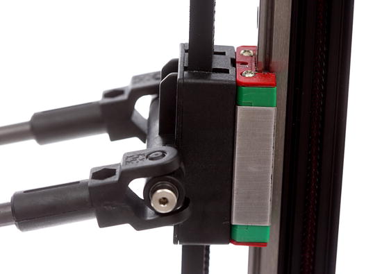
Figure 2-12. Linear rails (courtesy of Seattle Automationz, LLC)
Linear rails are very rigid and can provide additional rigidity to the frame of a delta printer. This is advantageous for the Kossel Pro because it uses the same 1515 extrusions as the Mini Kossel, which can flex if used in longer segments. The linear rails help stiffen the frame greatly.
Notice that there is an additional carriage that mounts to the linear rail carrier. The added complexity is the delta arm mount point positioned farther from the frame rail than the smooth rod version. This only means the offset is a bit larger, but otherwise isn’t a problem.
Linear rails are also very precise and do not require any adjustment other than periodic cleaning and a small amount of lubrication. However, linear rails are the most expensive option among the popular options for delta axis mechanisms. You can get linear rails in a variety of lengths.
![]() Note Linear rails are also used in Cartesian printers. For example, the fifth-generation MakerBot printers use linear rails.
Note Linear rails are also used in Cartesian printers. For example, the fifth-generation MakerBot printers use linear rails.
An alternative to the expensive linear rods is the use of Delrin-encased bearings that ride in the center channel of an aluminum frame extrusion. Some solutions use Nylon rollers. 3D printer enthusiasts have also had success using hardware-store-quality shower and screen door rollers. Figure 2-13 shows the roller carriage on a SeeMeCNC Orion printer.
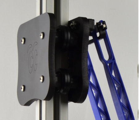
Figure 2-13. Roller carriage (courtesy of SeeMeCNC)
Notice that there are four rollers (two in the front, two in the rear). The pair of rollers on one side are fixed, and the pair on the other side use concentric cams to allow adjusting the tension of the rollers. Also notice that the roller carriage is larger than the linear rail. Indeed, the linear rail is mounted on the inside of the frame rail, leaving the sides and rear open; whereas the roller carriage requires use of both sides, as well as the inside of the frame rail. This limits the types of attachments that you can use on the frame.
However, this isn’t always the case. For instance, the roller carriages shown in Figure 2-13 block all four sides of the frame rail, which makes mounting anything on the rail within the axis travel range impossible. This isn’t the case if you use roller carriages for the Mini Kossel (thingiverse.com/thing:110283).
While this solution is a lot cheaper (perhaps by half), it is harder to set up because the rollers must be adjusted so that they press against the rails with enough tension to prevent the carriage from moving laterally or rotating, and yet not so much as to bind when moving along the channel.
I have found that the rollers need adjusting periodically and can be affected by environmental changes. This is made worse by carriages made from materials such as wood. Thus, while linear rails need occasional cleaning and lubrication, roller carriages require more frequent adjustment. They may or may not need periodic lubrication but that depends on whether the roller bearings used. Since delta printer axes are vertical, cleaning the channel isn’t normally an issue but is something you should inspect from time to time.
Recirculating Balls on Frame Rails
An interesting alternative to the expensive linear rails, and even the roller carriages, is a printable carriage that uses Delrin balls that ride in a recirculating channel. Johann C. Rocholl included this carriage in his Mini Kossel set of printable parts (https://github.com/jcrocholl/recirculating). Figure 2-14 shows an example of the carriage riding on an OpenBeamUSA 1515 aluminum frame extrusion. Thus, this solution only applies to the Mini Kossel (or similar designs using 1515 extrusions8).
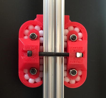
Figure 2-14. Recirculating ball carriage on frame rails
Not shown in this photo is an enlarged plate that mounts to the carriage on the interior side of the printer. Thus, this is a view of the exterior of the carriage (to show the recirculating mechanism). Since the dimensions are the same as the linear rail carriage alternative, you do not have to make any alterations in the firmware should you decide to experiment with replacing your existing mechanism with recirculating carriages.
This alternative works great for the Mini Kossel built from the OpenBeamUSA extrusions, but is a bit louder than the other solutions. This is because the Delrin balls tend to make a clicking sound as they recirculate. I’ve experimented with fine-tuning the ball channel, and that helped, but if you make the channel too small, the balls can bind.9
Like the roller carriage option, this solution also requires careful attention to keeping proper tension to keep the balls rolling smoothly. However, it does not need lubrication.
Delta Arms
Recall that each axis is connected to the effector via a carriage and a set of parallel arms (delta arms). The delta arms of most new delta printers are either 3D printed, injection molded, or assembled from joints glued to carbon fiber tubes.
There are several types of rod ends that are used. These include ball ends (e.g., Traxxas), concave magnets with steel balls (or similar), 3D printed or injection-molded joints, and joints with captured bearings. Except for the magnet option (discussed in more detail in Chapter 8), most delta printers include one of these types of rod ends. For example, the Mini Kossel design typically uses the Traxxas rod ends, the SeeMeCNC printers use injection molded parts (arms and joints), and the Kossel Pro uses injection molded parts with captured roller bearings.
The original Rostock and variants typically have printed arms. The Rostock Max v2 and Orion have injection-molded arms. The Kossel Pro, OpenBeam Kossel RepRap, and many Mini Kossel kits have carbon arms made with carbon fiber tubes. I have seen some examples with threaded rods, but these tend to be pretty heavy and may limit movement speed.
Stepper Motors
A stepper motor is a special type of electric motor. Unlike a typical electric motor that spins a shaft, the stepper is designed to turn in either direction a partial rotation (or step) at a time. Think of them as having electronic gears where each time the motor is told to turn, it steps to the next tooth in the gear. Most stepper motors used in 3D printers can “step” 1.8 degrees at a time. Figure 1-20 depicts a typical stepper motor.
Another aspect of stepper motors that makes them vital to 3D printers (and CNC machines) is the ability to hold or fix the rotation. This means that it is possible to have a stepper motor turn for so many steps, and then stop and keep the shaft from turning. Most stepper motors have a rating called holding torque that measures how much torque they can withstand and not turn.
Four stepper motors are used on a typical delta printer. One each is used to move the X, Y, and Z axes, and another is used to drive the extruder (E axis). Figure 2-15 shows a typical Nema 17 stepper motor (http://reprap.org/wiki/NEMA_17_Stepper_motor).
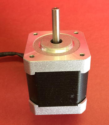
Figure 2-15. Stepper motor
Most stepper motors have a drive pulley mounted directly on the shaft, as you saw earlier in the discussion on extruders. However, some application, like the extruder included in the Mini Kossel design, use a geared extruder motor like the one shown in Figure 2-16. This stepper contains a set of planetary gears, giving the output a 5:1 ratio for more torque.
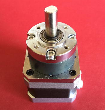
Figure 2-16. Geared stepper motor
Notice the cylindrical section on top of the motor. This contains the gear mechanism. Also notice that the shaft is considerably larger than a typical Nema 17 stepper motor (8mm vs. 5mm).
Build Plate
The build platform or build plate (sometimes called print bed) can be made from glass, wood, Lexan, aluminum, and composite materials. Glass is the most common choice. It is to this surface that the first layers of the object are extruded. Some build platforms include a heater element, called a heated build plate, placed under the glass. The heated plate is used to help some filament stick to the build plate. A build platform with the heated element is called a heated build platform. Figure 2-17 shows a heated build platform.
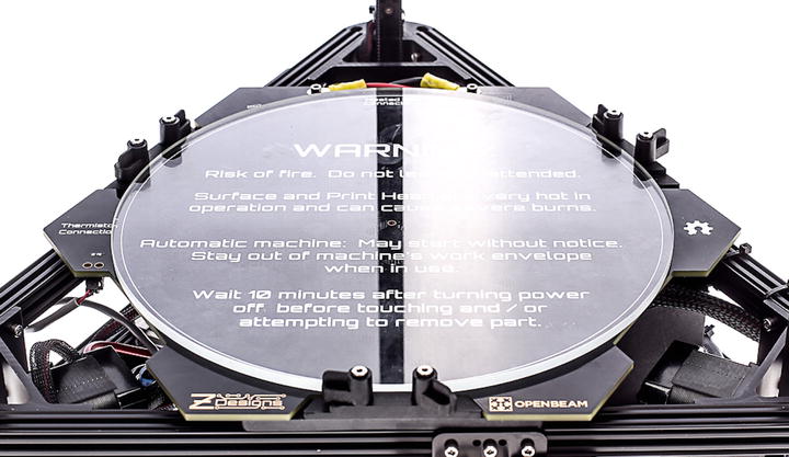
Figure 2-17. Heated build platform (image courtesy of Seattle Automationz, LLC)
Notice that the heated print bed is comprised of a thick printed circuit board (PCB) that includes a heating element and a thick circular plate of glass on top. Spring-loaded clamps hold the glass in place when printing.
One consequence of the mathematics and axis movement is that the valid movement area (without crashing into the towers) forms a rounded triangle. That is, the valid points where the printer can position the hot end, which you call the build volume. However, most delta printer designers have chosen to restrict the build volume to a cylinder to simplify things a bit. This is why you may notice some delta printers with manual Z-probes (such as the Mini Kossel and Kossel Pro) position the effector beyond the edge of the build volume (visually, the print bed) for deploying or retracting the Z-probe. These positions are still valid mathematical solutions.
Z-PROBE MECHANISMS AND THE BUILD PLATE
Most Z-probe mechanisms use a plunger mechanism that opens or closes a limit switch. The probe is moved from one position to another by repositioning then lowering and raising the effector until the switch is engaged. Thus, the Z-probe is connected to the effector.
However, there is another form of Z-probe that uses force resistor sensors (FSR) placed under the build plate. There are typically three FSRs wired such that if either is triggered, the electronics registers it in the same way as the limit switch. The FSR is triggered by the hot end as it is lowered (slowly) until it comes into contact and presses down on the print surface.
While most firmware supports FSR Z-probing, I have found it is a bit trickier to set up and tune than the plunger-type mechanical probes. Part of this has to do with how you do the Z-probing. That is, you must do it when the nozzle is hot and when there is no filament oozing from the nozzle. Also, if your print surface treatment is soft, it can absorb some of the force and therefore require more fiddling to get a proper initial Z-height. For more about using FSRs for Z-probing, see http://reprap.org/wiki/FSR.
Electronics
The component responsible for reading the G-codes and translating them into signals to control the stepper motors is a small microcontroller platform utilizing several components. Most notably are the microprocessor for performing calculations, reading sensors (endstops, temperature), and controlling the stepper motors. Stepper motors require the use of a special board called a stepper driver. Some electronics packages have the stepper drivers integrated, and others use pluggable daughterboards.
Most delta printers use a commodity-grade electronics board (RAMPS, RAMBo, etc.). The most common choice for smaller delta printers such as the Mini Kossel is RAMPS, which uses an Arduino Mega, a special daughterboard (called a shield) , and separate stepper driver boards. However, you may also see Printrboard (http://printrbot.com/shop/printrboard-rev-f/) and Azteeg X3 (panucatt.com/Azteeg_X3_Pro_p/ax3pro.htm) boards used. Another example is the Smoothieboard (http://smoothieware.org/smoothieboard), which has a 32-bit processor and dedicated firmware named Smoothieware (http://smoothieware.org/).10
The SeeMeCNC delta printers use the RAMBo electronics option, which is a single-board alternative to RAMPS that offers a better layout of the various connections. Figure 2-18 shows the RAMBo electronics board.

Figure 2-18. RAMBo electronics board (image courtesy of SeeMeCNC.com)
The electronics board is where you load the firmware, which contains the programming necessary for the printer to work. This is either a variant of Marlin (Mini Kossel, Kossel Pro) or Repetier-Host (Orion, Rostock Max v2). As discussed previously, this source code is compiled and then uploaded to the electronics board.
Now that I have discussed the axes and how they are moved, as well as the electric motors that move the component, the extruder, the hot end, the build platform used to form the object, and the electronics, it is time to discuss how a frame holds all these parts together.
Frame
Delta printers share a common design for the frame. While there are some differences in how the top and bottom portions are constructed and that there are several types of materials used, most designs use metal beams (sometimes called rods) or aluminum extrusions for the vertical frame components. I have seen at least one design that used an all-wood frame, but that was a custom design and not a popular choice.11
Recall that the delta printer has a base that secures the build platform, steppers for the axes, as well as a top section that holds the idler pulleys for the axes. Most designs incorporate the electronics, power supply, and other electronics in the lower section.
While the vertical axes use aluminum extrusions, the choice of frame material can vary among delta designs. The best frames are those that are rigid and do not flex when the extruder is moving or when the printer moves an axis in small increments. As you can imagine, this is very important to a high-quality print.
Some printers, such as the Mini Kossel and Kossel Pro, use the same aluminum extrusions to form the base and top of the printer. The Mini Kossel uses printed vertices bolted to the extrusions. The Kossel Pro uses aluminum vertices bolted to the extrusions. While both form very stiff components, the Kossel Pro is noticeably stiffer. Figure 2-19 shows the Mini Kossel top vertex and Figure 2-20 shows the same vertex on the Kossel Pro.

Figure 2-19. Mini Kossel top vertex
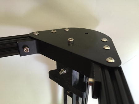
Figure 2-20. Kossel Pro top vertex
Notice that the printed vertex incorporates a channel for the horizontal frame components as well as a channel for the vertical-axis frame component. The small, round cap on top of the vertical frame component protects the belt tensioner and prevents accidental scratches or dings from collisions. Once you’ve dinged enough cabinets, you’ll want a set of these (thingiverse.com/thing:705791).
Notice that the Kossel Pro uses an additional steel plate bolted to the top of the vertex. This isn’t so much for rigidity, but it provides a secure mounting point for the belt tensioner.
The SeeMeCNC printers use a set of laser-cut melamine (two sheets of melamine with a wood core) that resists changes to environmental factors. The parts are cleverly designed to bolt together to form a very strong unit. The lower section is large enough to contain all the electronics, as well as the power supply and stepper motors. The top section is also very strong and contains the belt tensioners, as well as mounts for the extruder and a spool holder on top. Figure 2-21 shows the lower section of the Rostock Max v2 printer.
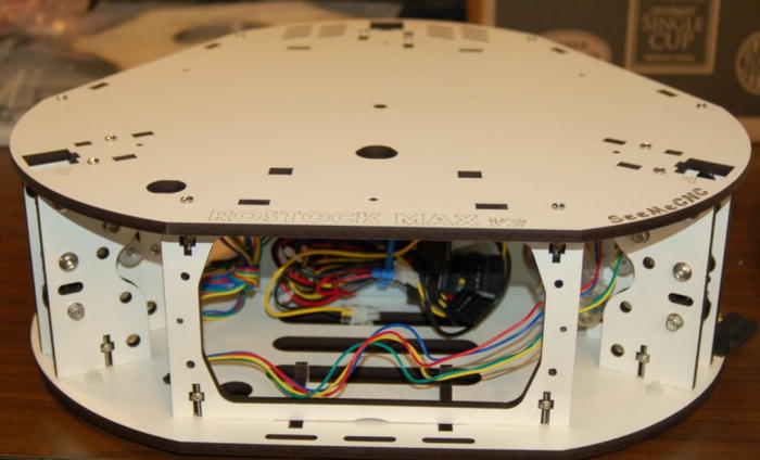
Figure 2-21. Melamine frame section (courtesy of SeeMeCNC)
Notice how the frame components are bolted together. The sections are laser cut to accept the nut for each of the bolts and hold securely; once tightened, they form a very strong connection. Notice also the X and Y tower mounts that incorporate the stepper motors and pulleys. Finally, notice that the section is large enough to house a full-sized PC power supply.
Now that I have discussed how delta printers are constructed, let’s look at three variant designs for delta printers.
Design Variants
In this section, I present three popular delta variants that represent excellent examples of good delta printers. I introduced these printers in Chapter 1. Here I present more information about each printer, including its capabilities, and a short review. Keep in mind these are only three examples of delta printers. While there are many others available, most are some variant of a Rostock or Mini Kossel. Thus, these printers represent what I consider the best examples of delta printers available.
The Rostock Mac v2 is an iteration12 of the original Rostock by Johann C. Rocholl, manufactured and sold by SeeMeCNC (http://seemecnc.com/products/rostock-max-complete-kit). The most significant aspect of this variant is the massive build volume. You can print objects up to 1300 cubic inches of build volume (an 11-inch diameter and a height of 14-3/4 inches). Indeed, with a spool of filament on the top-mounted spool holder, the printer itself is over 4 feet tall—presenting a very impressive profile.
I mentioned previously that the printer is constructed using laser-cut frame pieces bolted to large aluminum extrusions for the axes. However, the printer also uses injection-molded delta arms, joints, carriage mounts, and effector. There are also Lexan panels covering the upper and lower axis towers, making the overall package clean and modern looking. Figure 2-22 shows the Rostock Max v2. You can get the printer in either white or black Melamine panels.

Figure 2-22. Rostock Max v2
Notice that the printer comes with an LCD panel mounted on the front face of the lower panel. The base is large enough to house all the electronics and provides a solid foundation for the axes. The following provides an overview of some of its best features:
- Made in the USA by SeeMeCNC
- EZStruder mounted below the top-mounted spool holder
- 1.75mm filament, dual-heater hot end
- Removable 0.5mm nozzle (other sizes available)
- RAMBo by UltiMachine electronics
- Repetier-Host firmware
- Large heated build plate with thick Borosilicate glass
- Customizable electronics and hardware13
The Rostock Max v2 comes in kit form only. It is a nontrivial build given the number of parts and the moderately complicated hot-end assembly. Soldering, mechanical, and general electronics skills are required. That is, you should be familiar with using crimping tools, stripping, and soldering wires.
Although that may sound challenging, and it can be for those who have never built a 3D printer, SeeMeCNC provides a detailed, lengthy assembly manual with all the steps explained in clear language and reinforced with photos. I printed the manual so that I could make notes, and I was impressed by the size of the manual. It is very well done.
SeeMeCNC also hosts one of the best user forums I’ve seen (http://forum.seemecnc.com/). If you get stuck or have questions, one visit and a short query later, you will have your answers. Furthermore, the customer and technical support is also among the best in the business, easily overshadowing the larger vendors. For example, I made a mistake assembling one of the Lexan panels and managed to break it.14 SeeMeCNC sent me a new one the very next day and I received it only two days later. It doesn’t get better than that.
Calibration is easy and the manual makes the steps very simple. In fact, SeeMeCNC uses macros to help set the endstops and calibrate the axes. I explain this in much greater detail in Chapter 5. As for using the printer, once properly calibrated, the print quality is excellent. The hot end has operated flawlessly without extrusion failures or extraneous artifacts (e.g., lumps of filament on the part), and mechanical noise is moderate. It just works.
This printer has everything you need for great-looking prints. The only thing I found missing is an auto bed leveling (Z-probe) feature. However, I found there was no need for this, as the print surface is very flat with no visible imperfections. Indeed, when testing the maximum build diameter, I found that the hot end tracked evenly across the entire print bed. To understand this significance, consider that I have spent countless hours tuning and adjusting print beds on other printers, whereas the Rostock Max v2 was dead-on without any bed adjustment whatsoever!
In fact, I found the Rostock Max v2 to be a high-quality, professional-grade delta printer (despite the kit factor). If you need a delta printer with a large build volume and you can handle the assembly, the Rostock Max v2 will provide many hundreds of hours of reliable printing.
Kossel Pro
The Kossel Pro is a consumer-grade edition of the Mini Kossel made by OpenBeamUSA (kosselpro.com) and sold by MatterHackers (matterhackers.com/store/printer-kits). But it is much more than that. The printer is of very high quality and in all ways is a step up from its RepRap Mini Kossel ancestor.
Interestingly, OpenBeamUSA also offers a lower-cost version called the OpenBeam Kossel RepRap, which is a smaller version of the Kossel Pro that uses more plastic parts and fewer specialized parts. However, the OpenBeam Kossel RepRap shares many of the same parts as the Kossel Pro and it can be upgraded to the Kossel Pro with the purchase of an upgrade kit. Both printers are sold in kit form.
The most significant feature of this printer is the frame. As I mentioned previously, it uses the same OpenBeam 1515 aluminum extrusion that is popular with the Mini Kossel, as well as milled aluminum vertices and linear rails. There are very few plastic parts, all of which are high quality and injection molded. Another impressive feature is the effector, which incorporates a Z-probe, an always-on fan for the hot end, two part-cooling fans, as well as an LED light ring. Figure 2-23 shows the Kossel Pro. The Z-probe alone is a work of art.
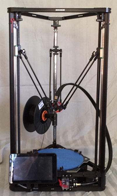
Figure 2-23. Kossel Pro
At first glance, this printer has all the most-requested features. Indeed, the Kossel Pro has an impressive list of features, as follows. The only thing I found oddly missing is a spool holder—there is not even a mount. However, due to the origins of the OpenBeamUSA components, it isn’t hard to find a spool holder that works. I created one myself from parts I found on Thingiverse (see Chapter 8).
- All-metal frame
- EZStruder mounted on the lower frame
- Designed to print ABS or PLA
- J-head 1.75mm hot end
- Custom-built electronics
- Marlin firmware
- Large heated build plate (optional) with thick Borosilicate glass
- Designed to print ABS (if heated build plate equipped) and PLA
Despite that this printer comes only in kit form, the build is very easy. In fact, one of the objectives of OpenBeamUSA is to make the printer easy to build quickly. This is achieved by using only bolt-on or plug-in wiring and components. In fact, the main wiring harness for the hot end, Z-probe, and light ring uses a single wiring bundle with molded connectors eliminating the need for any soldering. Furthermore, most of the tools you need are included in the kit.
I found the build a pleasure to work on. All of the parts are clearly labeled, and for the most part only fit together one way. There are some exceptions, so pay attention to the documentation! If there is any wrinkle, it is the documentation. While technically complete at the time of this writing, the documentation continues to evolve and I am happy that it is improving.
The Kossel Pro and OpenBeam Kossel RepRap are very new designs and are only just now moving from Kickstarter funding to full-on production. Thus, some things are still evolving and may change slightly. Fortunately, many of the minor issues in the first run of production kits have been solved. There is a small army of eager enthusiasts sharing the latest information about the printers.
Unlike the Rostock Max v2, there is no fine adjustability in the axis (i.e., endstops). This is partly because the assembly requires precise placement of the components during the build, and bolstered by superior-quality components and auto bed leveling (Z probing). However, I would have liked to dial-in the tower calibration rather than relying on auto bed leveling for any minor imperfections.
In using this printer, I found the mechanical bits superb examples of what printers should strive to be, but the print quality is not at the same level as other options. More specifically, it took me several experimental prints and numerous adjustments to get good print quality, but it will require a bit more tuning to perfect print quality. This is partly because the default settings in my software are not optimal for this printer (it’s too new) and partly because the firmware needs some tweaking.
For example, the effector-mounted part-cooling fans are a bit on the small size. I found I needed to run them at 100% to get better cooling for printing with PLA. If I could change one thing (and I may in the future), it would be to exchange the small axial fans with centrifugal fans. See the sidebar “Got Fans” in Chapter 8 for more details.
However, I would be remiss if I did not point out that this is a very new printer design, and many of the early adopters are experimenting along with me and sharing their results and findings. In fact, like the SeeMeCNC forum, the creators of the Kossel Pro routinely post and answer questions on the forum (http://forums.openbeamusa.com/forums/openbeam-kossel-reprap-and-openbeam-kossel-pro.7/).
Given that the printer is made from high-quality parts, maintenance should not be an issue. Indeed, as you will see in Chapter 7, none of the parts require any significant adjustment or lubrication. Other than adjusting belt tension and keeping the printer clean and lubricated (and only a tiny bit is needed), the printer should prove to be very low maintenance.
This printer is also a great platform for tinkerers due to the use of the OpenBeamUSA extrusions. These allow the bolting of all manner of accessories onto the frame. For example, in Figure 2-23 I show a spool holder (not included in the kit) and a mount for my MatterControl Touch.
I really like this printer. It is a sophisticated black-on-black, serious-looking delta printer that always gets a look when friends stop by. If you want a high-quality delta printer that has a moderate-sized build volume, and you want to experience building your own from a kit without the tedious soldering and electronics work, the Kossel Pro is an excellent choice. Given the documentation and the ever-expanding and improving user forums, I expect this printer to be a very popular choice for those who want a printer with better quality, reliability, and maintainability than the RepRap variants.
Mini Kossel
The Mini Kossel is one of the newest RepRap delta printers (https://github.com/jcrocholl/kossel), also designed by Johann C. Rocholl. As I mentioned in Chapter 1, the Mini Kossel is a hobbyist-grade (RepRap) printer that is entirely DIY. While you can buy kits that include all the parts, most people source their own parts or buy subcomponents from various vendors.
In fact, the Mini Kossel has been copied and modified by many people. I find a new variant of the Mini Kossel almost weekly. Some have minor changes, like using a different extrusion for the frame or a different carriage mechanism (see the earlier discussion on axis movement), but others have more extensive changes, such as alternative frame vertices and use of injection-molded parts, and a few have even increased the build volume.15
And due to its RepRap roots, on 3D printing forums such as Thingiverse (thingiverse.com) you can find all manner of useful add-ons, upgrades, and even a few embellishments. I have built several Mini Kossel printers and continue to improve them by experimenting with new designs—both my own and others (some work well, some not so much). You can find my designs on Thingiverse under my alias “oliasmage” (thingiverse.com/oliasmage/designs).
The Mini Kossel is one of the most (perhaps the most) popular delta printer variants available, other than the original Rostock. Figure 2-24 shows one of my heavily modified Mini Kossel printers.
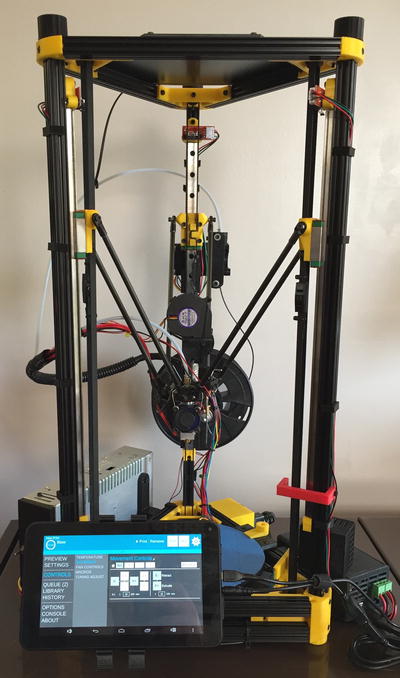
Figure 2-24. Mini Kossel
In Figure 2-24 you can see that I’ve added a mount for my MatterControl Touch, onboard power supply, spool holder, RAMPS box, power box, part-cooling fan, and many other things not shown or hidden by other parts.
Since this design is a pure RepRap, DIY endeavor, listing standard features isn’t helpful because there are so many options that you can choose. For example, you can choose your own hot end (1.75mm or 3mm, all-metal, peek, etc.), optionally add a heated build plate, add cooling fans, and so on. Indeed, there is almost no limit to what you can do with this little printer.
About the only thing I can say that is standard on most variants of the Mini Kossel is a small size. The printer is only a little over two-feet tall and takes up very little room. Although the build volume is quite small (about 5 to 6 inches in diameter and 6 to 8 inches tall), it is large enough to print most moderate-sized parts one at a time.
Building the printer is pretty easy if you have basic mechanical and electrical skills. The build time is only slightly less than what would be required for the Rostock Max v2, but because there are fewer parts, the build is a bit faster and the frame is less complicated to assemble.
While some vendors offer the Mini Kossel in kit form, few offer any form of help beyond the basic assembly.16 Fortunately, there are numerous articles, blogs, and independent forums that offer a lot of help. I would start with a visit to the Mini Kossel wiki (http://reprap.org/wiki/Kossel) and then search for topics you need help with, such as “Z-probe assembly” or “Mini Kossel calibration” . Another helpful forum is the RepRap general forum (http://forums.reprap.org/list.php?178), but enthusiasts building all manner of delta printers use this forum, so be aware that some of the information may not apply to the Mini Kossel. You can also check out the deltabot mailing list (https://groups.google.com/group/deltabot). When in doubt, ask.
Not surprisingly, given its small size and use of standard components, the Mini Kossel is the cheapest of the delta printers available today. If you opt to go without a heated print bed and use the less expensive axis components, you can find kits for under $500, and even a few around $400. I managed to source one of my Mini Kossel printers at about $300, but I opted to use some used parts from other Cartesian printers (e.g., motors, RAMPS).
If you are looking for a delta printer to start with, or want to experience building a delta printer from scratch or as a companion to a fleet of Cartesian printers, the Mini Kossel is an excellent choice. Build one for yourself or invite a friend to build one together.
Which Is Best?
The answer is “it depends.”17 Each printer represents an excellent choice. The answer lies in what you want to do with it. All require assembly, so that levels the field a bit, however, the Rostock Max v2 is the most difficult to assemble and the Kossel Pro the least.
![]() Tip Chapter 4 focuses on building delta printers. If you have never built a 3D printer and are contemplating one of these kits, be sure to read through Chapter 4 before you buy or begin your build.
Tip Chapter 4 focuses on building delta printers. If you have never built a 3D printer and are contemplating one of these kits, be sure to read through Chapter 4 before you buy or begin your build.
What sets them apart has to do with how much you want to tinker and modify. If you are the type who likes to change any component whenever you get a good idea (or sometimes not such a good idea), you will want to stay with the Mini Kossel. On the other hand, if you want a printer that has everything (except a spool holder), you should choose the Kossel Pro.
If you are choosing a printer on criteria such as customer support, documentation, and reliability, you will want to choose the Rostock Max v2 or perhaps the Kossel Pro, as the RepRap variants are purely DIY (you may get help from the Internet, but sometimes it can be a burden to sift fact from fiction).
Lastly, if you want build volume, the Rostock Max v2 has the largest, followed by the Kossel Pro, the OpenBeam Kossel RepRap, and the Mini Kossel, which has the smallest build volume.
WHY THE INTERESTING NAMES? DO THEY MEAN SOMETHING?
You may be wondering about the names of some of these printers. The original Rostock, and hence all the modern variants, was named after the town in northeast Germany where Johann C. Rocholl was born. Since the Mini Kossel is a RepRap design and most original RepRap printers were named after dead biologists, the Mini Kossel (and by inheritance, the Kossel Pro) is named after Albrecht Kossel, who was also born and studied in Rostock, Germany. Albrecht Kossel was a German biochemist and a pioneer in the study of genetics.
Summary
Delta printers represent a very different approach to 3D printing than Cartesian printers do. While they both share much of the same hardware, a delta printer’s axes mechanism is something magical to behold. This and the fact that delta printers have higher move rates and smaller footprints make delta printers more enthusiast- and hobbyist-friendly than some of the Cartesian options. Indeed, I’ve found I use my Cartesian printer less and less, favoring the delta printers for critical prints.
In this chapter, you discovered how delta printers work and learned about the mathematics of delta printers, the types of hardware used in the frame and axes, and the electronics, including the hot end and the heated build plate. Lastly, you explored three types of delta printers that you can buy today.
In the next chapter, you will discover the software side of 3D printing, including how models are turned into objects and how the printer is controlled via the firmware.
_________________________
1Some earlier firmware did not support delta printers. Fortunately, Marlin and Repetier-Host fully support delta printers.
2It’s on the Internet, so it must be true, eh?
3See themathpage.com/atrig/solve-right-triangles.htm.
4The actual Z position is the minimal Z-height. For example, the nozzle is normally positioned 0.15mm – 0.25mm above the print bed at Z = 0.
5Yes, this is a bit of horse-before-the-cart, but I feel it is important to understand how the mathematics works in a general sense, which should help you understand what all these values are and how they affect the calculations.
6There are delta printers with an extruder directly on the effector, and others where the extruder is suspended on elastic strings just above the effector with a very short Bowden tube.
7See matterhackers.com/store/printer-accessories/v6-hot end-full-kit-1.75mm-universal.
8You could scale or modify this design to accommodate other frames, provided there is a center slot or channel.
9Nobody wants that!
10Johann C. Rocholl suggests, “I predict it is going to completely replace RAMPS and Marlin in the next couple years.”
11All wooden frames are more susceptible to environmental conditions, such as varying humidity and temperature making it a less than ideal material choice. Note that Melamine dramatically reduces these effects.
12Perhaps an evolution.
13Look closely at the photo. Notice the custom spool roller on top.
14While I normally test-fit panels such as this, my one lapse ended in a spectacular part failure. Always test fit your parts before installing them, especially tension-fit mounts.
15I saw one described as a Mini Kossel XL. What?
16Which, with few exceptions, are normally very terse.
17I know, I know. It sounds like I don’t want to choose, but in this case it’s true.