User Interface
This lesson covers the essentials of the 3ds Max user interface. The user interface, or UI for short, is the method by which the user communicates with the software. The UI is split into two main components: the Graphical User Interface or GUI (what you see on the screen), and input devices such as keyboard and mouse. You can customize most of the 3ds Max UI.
After completing this lesson, you will be able to:
• Use the UI components in the 3ds Max interface.
• Manipulate and configure the viewport area.
• Use the command panel to create a simple object.
• Control animation in a 3ds Max scene with the animation playback controls.
• Manipulate a model in the viewport with viewport controls.
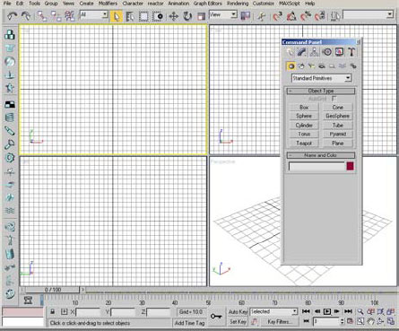
Once you start 3ds Max you will encounter the following GUI on your screen.
The UI is logically laid out and easy to use. We’ll go though the various elements, so you understand how to work with them and the terminology used.
The viewport area of the UI displays the scene you are working on. 3ds Max is quite flexible with how you can arrange the viewports and how your model appears in each viewport.
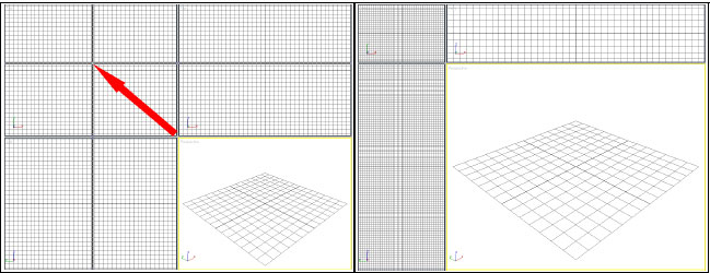
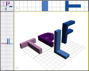
The size of the viewports can be easily adjusted by clicking the line between the viewports, and then dragging it to another point in the viewport area. In the illustrations below, the default four equal viewports have been changed to a large Perspective viewport by clicking and dragging the center to the upper left.
By default, 3ds Max opens with four equal-sized viewports displayed in the UI. You can change this layout with the Viewport Configuration dialog.
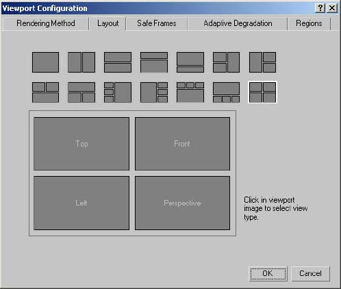
The Viewport Configuration dialog shows the variety of viewport layouts available. You simply choose one to make that layout current. You can also click the active layout in the dialog to change what the viewports show before exiting the dialog. Which layout you choose depends largely on your personal preference and the type of scene you are working on.
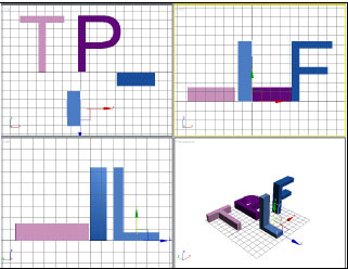
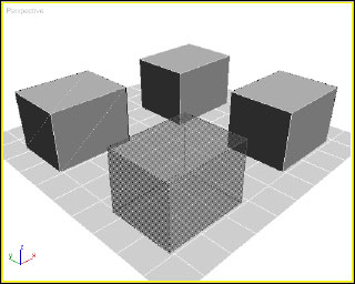
By default, the four viewports that are displayed when 3ds Max is started are Perspective view, Front view, Top view, and Left view. Each one of these viewports has its own home grid. The home grid is the working or construction plane of the view. By default, objects are created on that plane or grid.
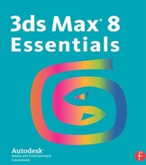
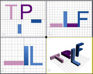
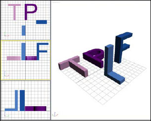
When you make a viewport active by clicking it, a yellow border appears. The corresponding home grid also becomes current. The following illustration shows four 3D letters, each created in a different viewport while that viewport was active. P is for Perspective, L for Left, T for Top and F for Front.
Hint: If you don’t like the default layout of the 3ds Max viewports, you can create your own layout and save it as maxstart.max in the scenes folder. 3ds Max will look for this file and use it as a base template when you start and reset the software.
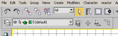
The menu bar, found at the top of the 3ds Max user interface, contains a series of pull-down menus. These include some common menus, such as File and Edit, found in most Windows applications.

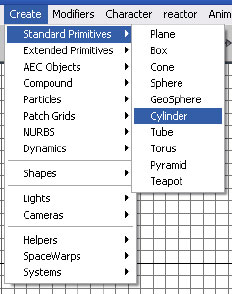
Create menu with submenu. Most Create functions are available here.
In addition, the menu bar contains many functions found in 3ds Max that also appear in other menus. For example, the Create menu, shown above, duplicates the Create commands on the command panel.
Toolbars play an important role in the 3ds Max UI. You can dock toolbars at the edge of the viewports, or float them on top of the 3ds Max window or off to the side, for example, on a second monitor.
Toolbars docked on top and side of the UI, and floating
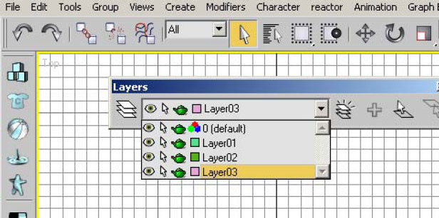
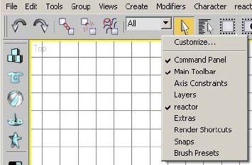
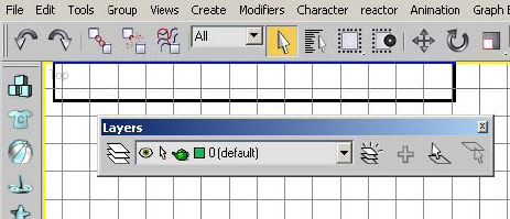
Toolbars are not always displayed by default. For instance, the Layers toolbar does not display when 3ds Max is launched for the first time. To display a toolbar, right-click a blank part of the toolbar, such the area just below a drop-down list.

Right-click menu showing the displayed
A list of toolbars currently defined in the UI appears. The check marks indicate which toolbars are currently on screen.
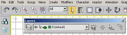
You can dock a toolbar by dragging the toolbar’s title bar to the edge of the viewport area.

Dragging a floating toolbar to a docked position
The dragged rectangle changes shape when you can release the mouse and dock the toolbar.
Toolbar now docked in position
You can undock a docked toolbar by dragging the double lines at the left end of the toolbar into an open area of the UI.
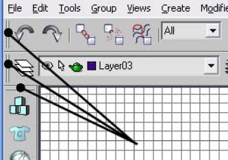
Handles of toolbars used to undock the toolbar
If the 3ds Max window uses a resolution lower than 1280 x 1024, the main toolbar is not fully visible. If you don’t see the teapot icons at the right end of the toolbar, this is the case.
Buttons at the end of the main toolbar
You can scroll the toolbar by positioning the mouse cursor over an empty area of the toolbar. The icon then changes to a Pan hand, and you can drag horizontally or vertically, depending on the orientation of the toolbar.
Exercise 1: Working in the User Interface
Now that you have seen a few elements of the UI, you can start using them.
1. Launch 3ds Max.
2. From the File menu, choose Open.
3. Navigate to the directory that contains your lesson files and open the file letters.max.
If the Units Mismatch dialog appears, click OK to accept the default option.
4. In the viewport area of the UI, position your cursor at the center of the viewports.
5. Click and drag the center point to the upper left of the viewport area.
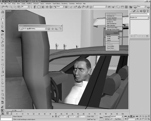
6. In the largest viewport, right-click the Perspective label.
The viewport right-click menu appears.
7. Choose Configure from the menu.
8. Click the Layout tab on the Viewport Configuration dialog.
9. Change the viewport layout by choosing the third image in the second row of layouts.

10. In the Viewport Configuration dialog, click in the Left viewport. In the menu that appears, choose the Right option to change the viewport to a right-hand view.
The Layout changes to three small viewports on the left and one large viewport on the right.

11. Click OK to exit the Dialog.
12. Click the Front viewport. Its border turns yellow.
13. Press the B key on your keyboard.
The view in the viewport changes to the Bottom view. Preset hotkeys make it easier and faster to switch views.
14. In the Bottom viewport, right-click the viewport label. Choose Views > Back to switch to a rear view of the scene.

If there is no hotkey, or you cannot remember the hotkey, you can right-click the viewport label and choose Views to choose from the list of available views.
15. Go back to the standard four viewport configuration either through the Viewport Configuration dialog or by choosing Reset from the File pull-down menu.
Note: When you reset 3ds Max, the viewports are cleared of objects and returned to their default setup.
In the next exercise, you’ll create some objects using the user interface.
1. Start or reset 3ds Max.
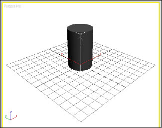
2. From the Create pull-down menu, choose Standard Primitives > Cylinder.
3. In the Perspective viewport, click and drag the base radius of the Cylinder.
4. Move the cursor upwards and then click to give the cylinder a positive height.
You will want to come back to this point in the scene, so you will use the Hold and Fetch commands, found on the Edit pull-down menu.
5. From the Edit pull-down menu choose Hold. This bookmarks the progress up to this point.
6. Next you’ll create another object, this time using the command panel. Click the Create tab.
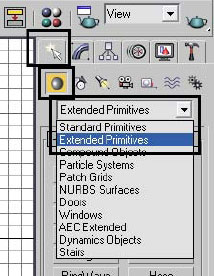
7. Click the Geometry button.
8. Choose Extended Primitives from the list.
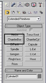
9. Click the ChamferBox button.
10. In the Perspective viewport, click and drag to set the base. Release the mouse button.
11. Move the cursor vertically and click to set a positive height.
12. Move the cursor to the left and click to set a positive chamfer radius.
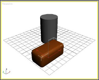
13. Right-click the Front viewport to make it active.
14. Make sure the Create panel and the Geometry button are still active.
15. From the drop-down list, choose Standard Primitives.
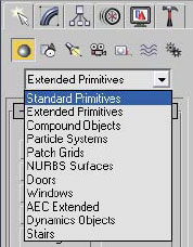
16. Click the Cylinder button.
17. Create the radius of the base of the cylinder in the Front viewport.
18. Drag the cursor upwards and then click to create a positive height for the cylinder.
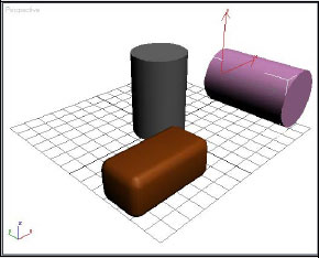
This cylinder is oriented differently from the first one because of the different construction planes being employed by the Front and Perspective viewports. The Front viewport’s construction plane is more like drawing on a wall, whereas the Perspective viewport works more like the Top view, like drawing on the floor.
19. Create another Cylinder in the Left viewport.
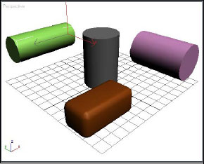
Note the orientation and construction plane of this new object.
20. From the Create pull-down menu, choose Shapes > Line.
This activates the Create panel, the Shapes button, and the Line button. The command panel responds to commands entered elsewhere in the interface.
21. Press ESC to terminate the command.
22. From the Edit pull-down menu choose Fetch. When prompted “About to Fetch?”, click Yes.
23. Your scene reverts to the bookmark you set earlier using Hold, when there was only one cylinder in the scene.
Exercise 3: Customizing Toolbars
In the following exercise, you will look at how to manipulate toolbars in the interface.
1. Restart or reset 3ds Max.
2. Right-click the grey area just under the first drop-down list on the main toolbar.
The main toolbar, command panel, and Reactor toolbar are currently visible.
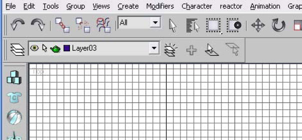
3. Click Layers to enable this toolbar.
The Layers toolbar appears, floating in the upper-left area of the viewports.
4. Right-click the main toolbar again.
5. Choose Reactor. The Reactor toolbar disappears.
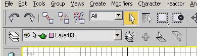
6. Drag the title bar of the Layers toolbar and place it just below the main toolbar.
7. When you are in the correct position to dock the toolbar, the appearance of the cursor and dragged window change subtly. When you release the mouse button, the toolbar appears in its docked position.
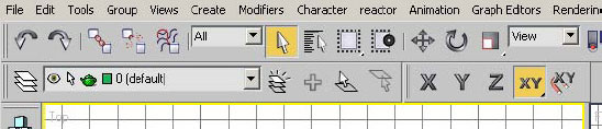
8. Enable the Axis constraints toolbar and dock it right behind the Layer toolbar.
9. Remove the Layers toolbar, and then enable it again. The toolbar remembers its last position and docked status.
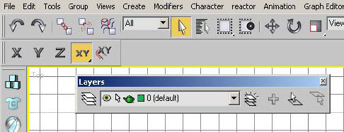
10. Click and drag the two vertical lines at the left end of the Layers toolbar. Drag inside the viewports area and release the mouse button.
11. Click the X button on the Layers toolbar title bar to close the toolbar.
12. On the Customize menu, choose “Revert to Startup Layout”. Click Yes when prompted. The UI returns to its initial state.
The command panel is the most-used area of the user interface. The command panel is organized in a hierarchical fashion, with six panels, activated by clicking tabs at the top of the panel.
Some of the command panels contain buttons and drop-down lists that further organize the panel. For example, the Create panel includes a row of buttons. Depending on which button is active, there may be a drop-down list.
As with toolbars, you can float or dock the command panel.
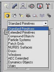
The first command panel is the Create panel. It contains different levels of creation parameters that allow you to build different types of geometry. By default the Create > Geometry > Standard Primitives area of the panel is displayed. Briefly, some areas of the Create panel are described below.
Geometry
In the Geometry area, you find commands to create 3D geometric objects.
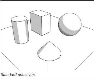
Standard primitives are rudimentary 3D geometric objects.
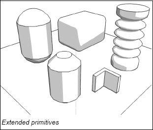
Extended primitives are more complex than standard primitives.
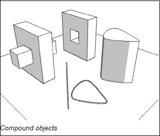
Compound objects usually combine two or more objects together.
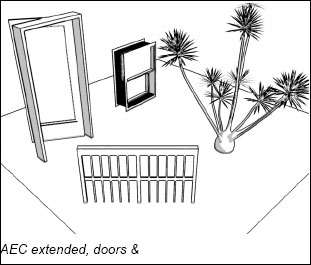
AEC extended, doors, and window objects are generally meant for AEC (Architecture, Engineering, and Construction), but can be useful in other applications.
Shapes
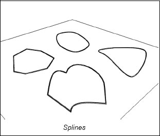
Shapes are divided into two basic types: splines and NURBS curves. Shapes are typically 2D but can be created in 3D as well.
Splines are based on Bi-Cubic Rational B-Splines. This allows you to draw straight lines and curved lines based on the properties of the vertices of the spline.
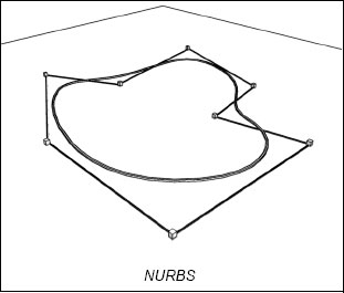
NURBS, or Non-Uniform Rational B-Splines, function differently from other splines in 3ds Max. You can control the NURBS curve from a point or from a control vertex which is off the actual curve.
Lights
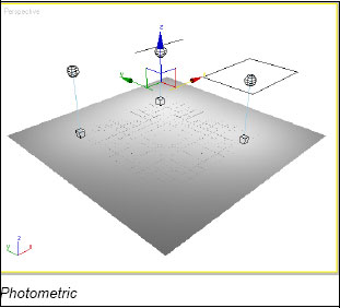
Lights are used to illuminate the 3D scene in 3ds Max. Two types of lights are available: standard and photometric.
Standard lights comes in a variety of types. They are not based on real-world scale or illumination.
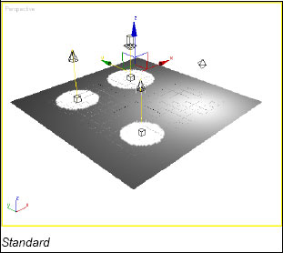
Photometric lights are similar in type to standard lights. However, they are based on real-world scale, illumination, and lighting distribution.
Cameras allow you to frame your compositions in a way that captures the attention when an action is taking place. There are two types of cameras in 3ds Max, both of which can be animated.

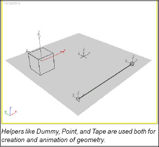
Helpers
There are a number of helper types. A helpers is a non-renderable object whose purpose is to help you model and/or animate objects in the scene.
The last two buttons on the Create panel represent the Space Warps and Systems areas. These areas contain advanced features beyond the scope of this book, although some elements will be covered in later lessons.
The Modify panel controls let you modify the base parameters of objects or change them using modifiers.
The Hierarchy panel is used when manipulating objects which are linked to one another. In such a situation the objects are in a parent/child relationship. This panel controls some of the relationships between these objects. The panel is also used to control the location and orientation of an object’s pivot point.
The Motion panel is used to control the animation of objects. Animation controllers can be assigned to objects in this panel.
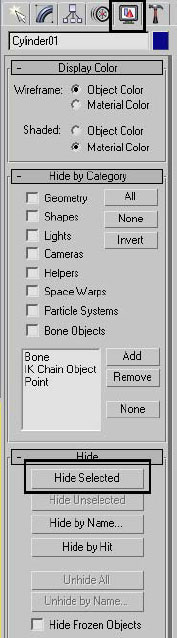
The Display panel is used to control an object’s color, visibility, freeze/thaw status, and other display properties.
The Utility panel contains a variety of commands generally not found elsewhere in the user interface.
Exercise 4: Using the Command Panel
In this exercise, you will create and modify a simple object using the command panel.
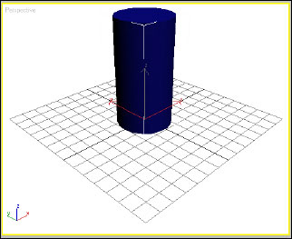
1. Start or reset 3ds Max.
2. On the command panel, choose Create > Geometry and then click the Cylinder button.
3. In the Perspective viewport, drag out the base radius of the cylinder. Release the mouse button, move vertically, and then click to set the height of the cylinder.
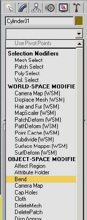
4. On the command panel, click the Modify tab.
5. On the Parameters Rollout, change the Radius to 10, and the Height to 60.

The base parameters of an object can be changed at the time of creation, but it is recommended that you switch to the Modify panel before changing these values.
6. Click the Modifier List, and choose Bend from the list.
7. On the Parameters Rollout change the Angle value to –100 and the Direction value to –90.
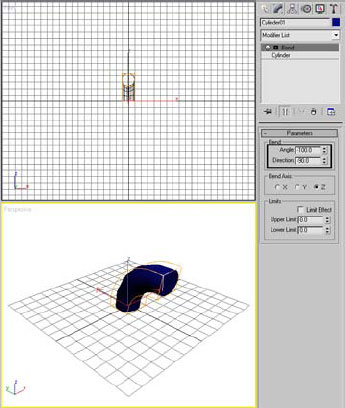
8. Right-click the Direction spinner. This sets the value to 0.
Note: In general, whenever you want to set a value to 0, you can right-click its spinner. There are a few exceptions to this rule where the value will go to 1.
9. ![]() Click the Zoom Extents All button in the lower-right area of the UI.
Click the Zoom Extents All button in the lower-right area of the UI.
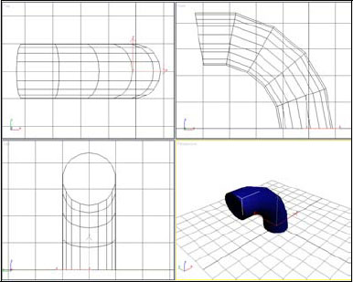
10. Go to the Display tab, and click the Hide Selected button. The object disappears.
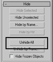
11. In the same area of the UI, click the Unhide All button. The cylinder reappears.
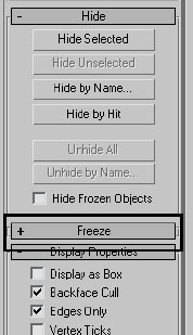
12. Click the Freeze label to expand the Freeze rollout.
13. Place the cursor in an empty area of the rollout. The cursor turns into a Pan hand.
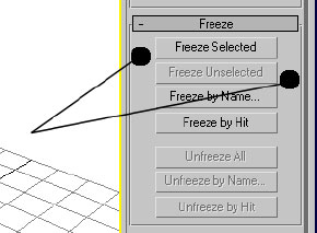
14. Click and drag upward until the lower area of the panel appears.

Other important UI Elements include the quad menu, dialogs, and several areas at the bottom of the 3ds Max window.
The quad menu is a floating menu that adapts to the context, whenever the menu is activated. In order to access the menu, right-click in the active viewport.
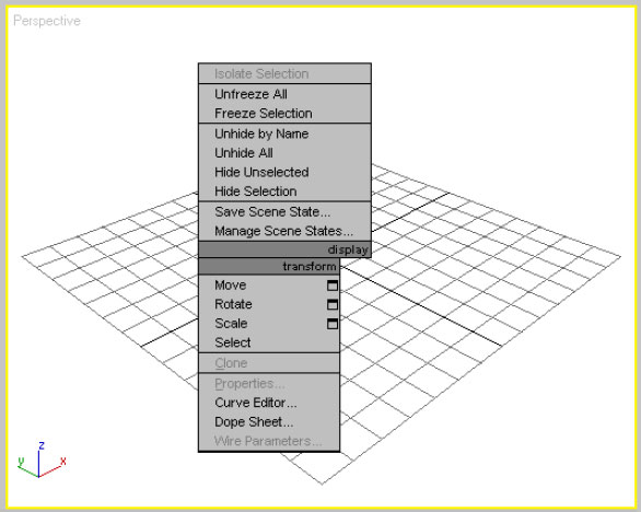
Quad menu when no object is selected
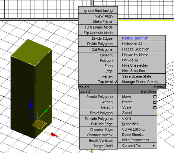
Quad menu when a 3D Editable Mesh object is selected
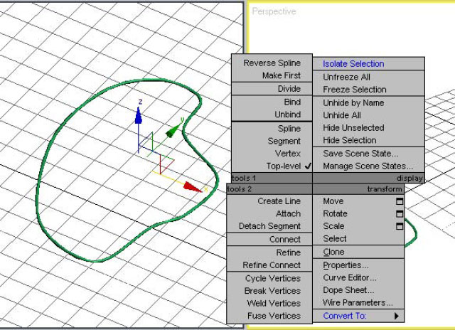
Quad menu when a 2D Editable Spline object is selected
Dialogs are used to present the user with information that doesn’t fit easily into other areas of the UI. These may contain a large amount of information, graphs, thumbnails, schematic representations, and so on. Some typical dialogs include the following.
File Dialogs
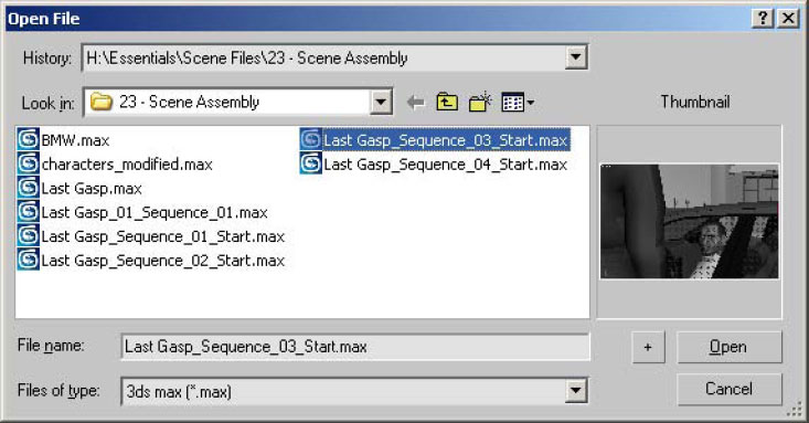
File dialogs such as Open and Save look similar, and have the ability to display thumbnails.
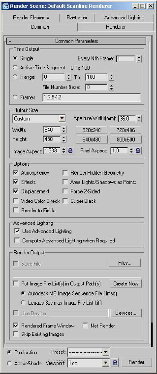
The Render dialog is typical of many dialogs in 3ds Max. It contains options organized in many rollouts on multiple tabs.
Track View is a tool that helps you edit and control the animation in the scene.

The Track View Curve Editor shows animation data in a curve format that allows you to adjust your animations easily.
Time Slider, Track Bar, and Timeline
The area just below the viewports is where the time slider, track bar and timeline are found.
You can scrub the animation backward and forward by dragging the time slider. Alternatively, the arrows on the time slider allow you to move one frame at a time.

The track bar shows you the keys of a selected, animated object along a timeline. In this example, the timeline is displaying in frames and showing that the selected object has keyframes at frames 0, 60, 65, and 70.
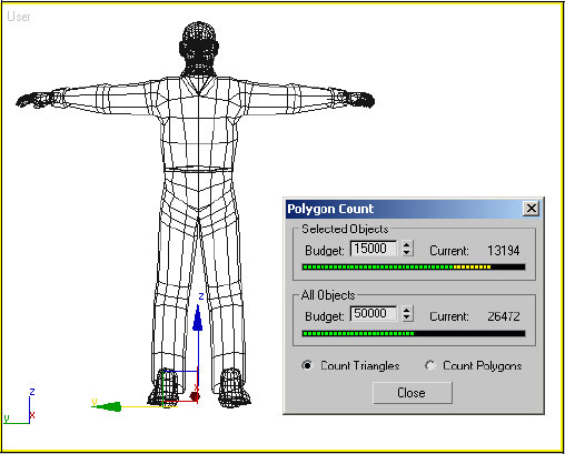
The status line shows information pertaining to the object selected and the scene.
![]()
In the above example, the status line shows that one object is selected, as well as the coordinates of the pivot point of that object.

In the above example, the status line shows two objects selected. The prompt line prompts you to perform an action. In this case, the XYZ coordinates are blank because multiple objects are selected.
There are two approaches to enable animate mode in the main UI. They are both identified in the animation controls area. These two modes are called Auto Key and Set Key. When Auto Key is active, the frame around the active viewport turns red, as does as the time slider background. When this mode is on, most changes that you apply in 3ds Max are recorded and can be played back later.
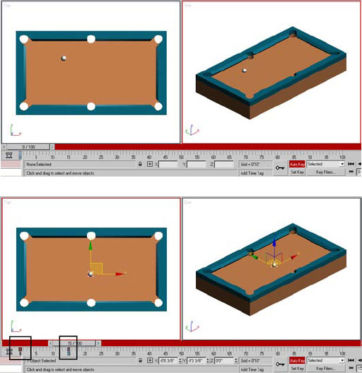
When Auto Key is on, you move the time slider to the desired frame, and then make a change to the scene, in this case, moving the ball between two points in space. At frames 0 and 15, keys that retain the state of an object are automatically created for the ball’s motion.
![]()
Set Key is the other animation approach that favors pose-to-pose animation. Set Key mode is usually used for animating characters. In Set Key mode, changes are not recorded unless you click the Set Keys button.
The playback area controls let you play your animations live in the viewports. Also here are tools you can use to adjust the animation.
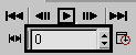
The upper part of the playback controls area work much like the buttons on a VCR or DVD player. The current frame is listed in the numeric field. When you change the number, you go to that frame.
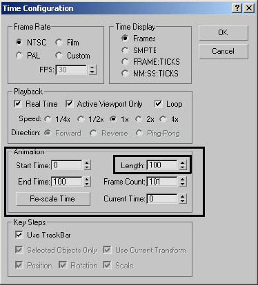
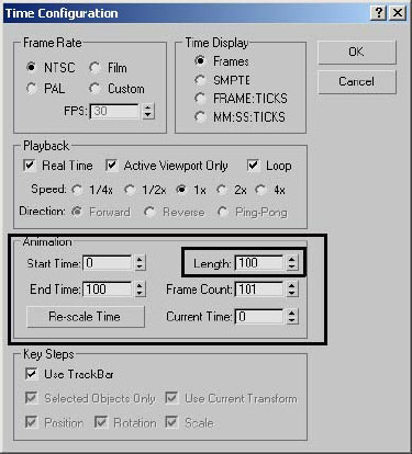
The Time Configuration button at the extreme lower right of the group brings you to the Time Configuration dialog. One of the things you will frequently do in this dialog is change the length of the animation.
Exercise 5: Using the Animation Playback Controls
In the following sequence you will use the animation controls to play back and adjust a simple animation.
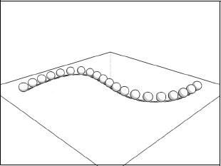
1. Open the file Pool Table Cue.max.
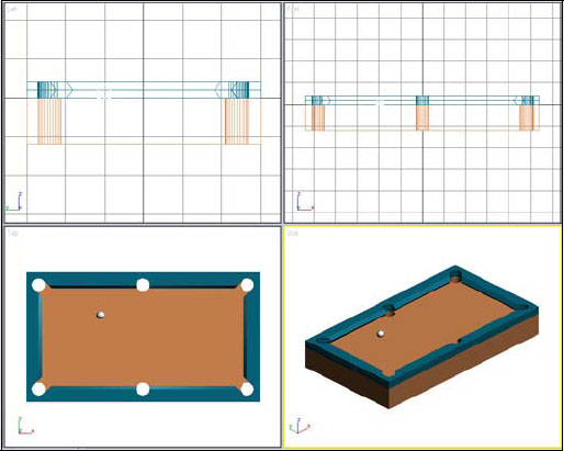
2. Right-click the User viewport to make it active.
3. ![]() Click the Play Animation button. The animation plays in the User viewport.
Click the Play Animation button. The animation plays in the User viewport.
4. While the animation is still playing, right-click in the Top viewport. The animation playback switches to that view.
5. Click the Play Animation button again (it now looks like a “pause” symbol) to stop the playback.
6. Click the white Cue Ball object to select it.

An animated object will typically have keys along the timeline. These represent pivotal moments in the object’s animation.
7. Drag the time slider back and forth between frames 50 and 70. The ball moves towards and away from the bumper of the table.
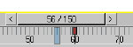
8. Leave the time slider on frame 60. Frame 60 is the frame where the ball changes direction, as you would expect from hitting a bumper on a pool table.
9. Click the key at frame 60. It turns white, and the mouse cursor becomes a left/right arrow while over the key.
10. Drag the marker to frame 40.
11. Play the animation again. The ball gets to the bumper more quickly now.
You can break down the controls of the viewports into two general areas. The viewport navigation buttons allow you to control the orientation and positioning of the views in the viewports. The viewport right-click menu allows you to control the configuration, rendering mode, and type of view in the viewport.
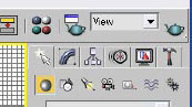
The viewport navigation tools are found at the lower-right of the 3ds Max UI. These buttons let you control the positioning of the vantage point of the viewer of the 3D scene. The icons are context sensitive and can change depending on the type of view currently active.
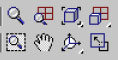
Above is the most common layout of the viewport control tools. This layout appears when a orthogonal viewport is active, such a Top, Front, or User viewport.

Some of the buttons in this area contain flyouts with additional options. After you choose a different flyout button, it becomes current, making it easier to choose a second time.
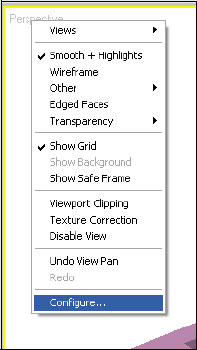
When you right-click a viewport label, a menu appears. This menu contains a number of commands for controlling the viewports.
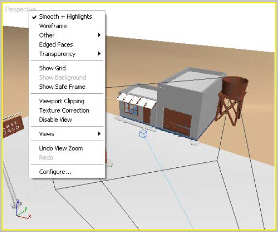
The viewport right-click menu controls rendering levels and the configuration of the viewport layout.
The viewport right-click menu offers a number of different rendering modes. You’ll probably use these most often:

Viewport rendering set to Smooth + Highlights.
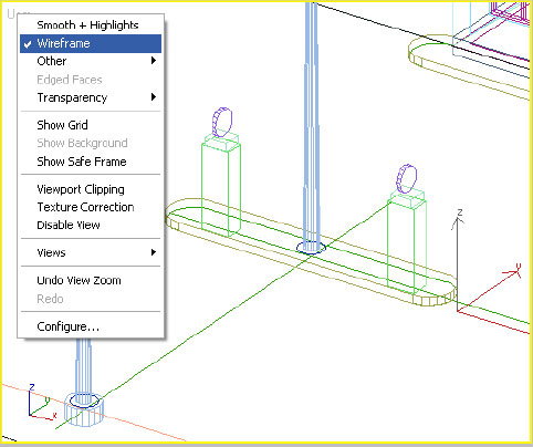
Viewport rendering set to Wireframe.
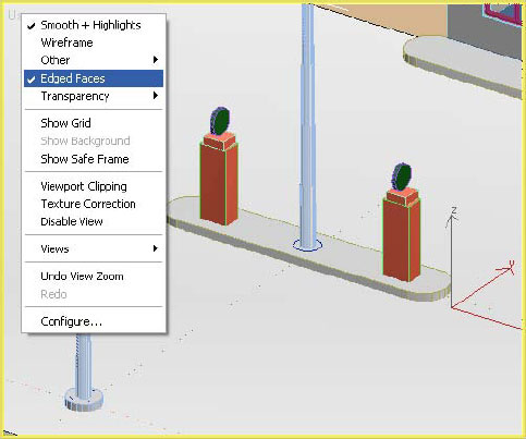
Viewport rendering set to Smooth + Highlights with Edged Faces on. This combination of shaded and wireframe views can be useful when modeling.
Since most animators switch among these rendering modes frequently, 3ds Max includes predefined hotkeys to speed access to these modes.
• The F3 function key toggles between Wireframe display and Smooth + Highlights.
• The F4 function key toggles Edged Faces display.
Grid Toggle
You can toggle the grid that appears by default in the viewports through the viewport right-click menu. Choosing Show Grid from the menu toggles the grid status on or off. The G hotkey does the same thing.
The Undo View operation function in the viewport right-click menu (third option from the bottom) undoes the last view operation, be it a Zoom, Pan, Arc Rotate, etc. The wording of the entry changes based on the last operation. The SHIFT+Z hotkey has the same result.
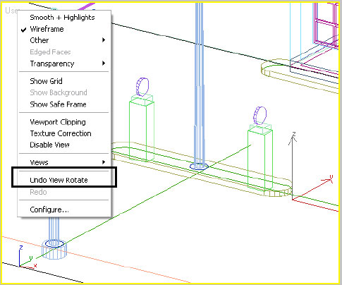
Undo view operations with the viewport menu.
Exercise 6: Orthographic View Manipulation
In the following exercise, you will look at how to manipulate a model in one or more orthographic viewports.
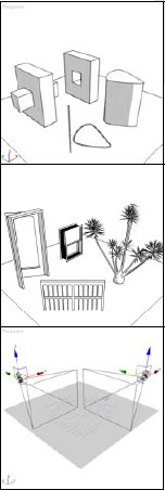
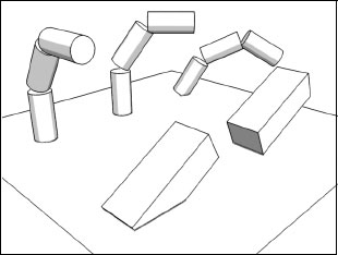
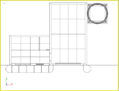
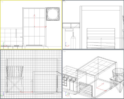
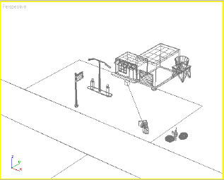
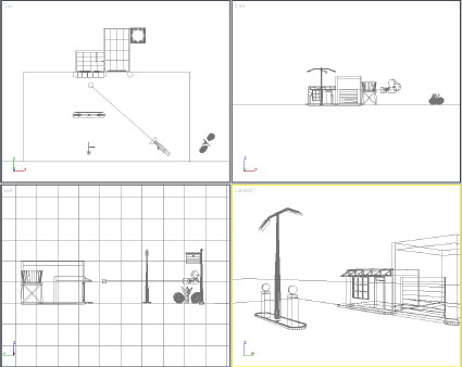
1. Open the file Gas Station Blockout.max. This is a rough block-out of a scene that you will be working on in more detail later.
2. Right-click the Top viewport to make it active.
3. ![]() Click the Zoom button in the viewport controls area.
Click the Zoom button in the viewport controls area.
4. Zoom in with the cursor approximately centered on the building.
The building scrolls out of the viewport. You can adjust the zoom control so that it zooms about the mouse button.
5. Use the SHIFT+Z hotkey to undo the zoom operation in the Top viewport.
6. From the Customize pull-down menu, choose Preferences.
7. On the dialog that appears, click the Viewports tab.
8. Turn on Zoom About Mouse Point for both Orthographic and Perspective views.
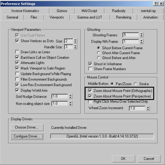
9. Click OK to exit the dialog.
10. Repeat the operation of zooming into the model with the cursor centered on the building.
Depending how close you placed the cursor to the center of the building, the building will stay visible in the viewport much longer.
11. Undo the View operation (SHIFT+Z).
12. ![]() With the Top viewport still active, click the Zoom Extents button.
With the Top viewport still active, click the Zoom Extents button.
All visible objects in the scene are now displayed in the Top viewport. The building is only a small area in the center.
13. ![]() Click the Zoom Extents all button.
Click the Zoom Extents all button.
All the Viewports zoom out in a similar fashion. If you want to get back to your previous views in each viewport, you have to do an Undo Viewport operation in each viewport individually. If you would like to isolate a few objects, you can use Zoom Extents Selected.
14. Press the H key on your keyboard to bring up the Select Objects dialog.
15. Highlight the object Bldg_High, and then click the Select button on the dialog.
16. Click the Zoom Extents All button and hold until the flyout appears.
17. On the flyout, choose the button with the filled white square.
All four viewports zoom about the selected objects.
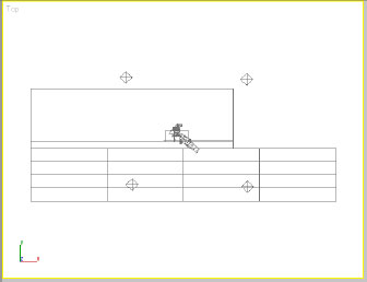
18. ![]() Click the Front viewport and then use the Zoom tool to zoom out of the view about 50%.
Click the Front viewport and then use the Zoom tool to zoom out of the view about 50%.
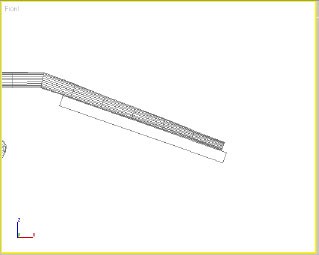
19. ![]() Click the Region Zoom button and then drag a rectangular area around the right lamp to zoom into that lamp.
Click the Region Zoom button and then drag a rectangular area around the right lamp to zoom into that lamp.
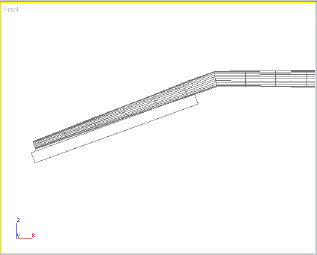
20. ![]() Click the Pan tool and then pan the view to the right so you display the left-hand lamp.
Click the Pan tool and then pan the view to the right so you display the left-hand lamp.
21. Roll the middle mouse wheel in either direction to zoom your view in and out. To pan the view, hold down the middle mouse button and move the mouse.
22. Right-click the User viewport to make it active.
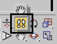
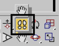
23. ![]() Click the Arc Rotate button.
Click the Arc Rotate button.
A circle with four small squares at the quadrants of the circle appears.
24. Click the right-hand square and drag left to right.
25. Click the upper square and drag up and down.
Using these squares limits the arc rotate motion. Clicking inside the circle provides you freer movement in both horizontal and vertical directions. Clicking outside the circle provides you with a roll that can sometimes be difficult to control.
26. Undo your viewport operations (SHIFT+Z) to get back to the original view.
27. Select the object Bldg_High, if necessary. (H)
28. ![]() On the Arc Rotate flyout, click the icon with a filled-in white circle.
On the Arc Rotate flyout, click the icon with a filled-in white circle.
29. Perform some of the same operations you did previously and note that the rotations now occur around the building (the selected object).
30. ![]() The last button in the viewport controls group is Maximize Viewport Toggle. When you choose this icon, the active viewport toggles to full screen.
The last button in the viewport controls group is Maximize Viewport Toggle. When you choose this icon, the active viewport toggles to full screen.
Exercise 7: Perspective View Manipulation
In the following exercise you will learn how to manipulate a model in one or more Perspective viewports.
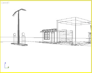
1. Open the file Gas Station Blockout_01.max.
2. Make the User viewport active and press the P key on the keyboard.
The User viewport changes to a Perspective viewport. One of the buttons in the viewport control group changes.
3. ![]() Click the Field Of View button.
Click the Field Of View button.
4. Click and drag in the Perspective viewport and the view will move in and out along the perspective view line.
Note: Use care with the Field of View tool. Extreme distortion of the perspective can occur if the field of view is made too large. Use Undo View operation (SHIFT+Z) to return to the previous view.
5. Type the Letter C and the Perspective View will change to the view of a camera present in the scene.
If there was more than one camera, 3ds Max would prompt you for which camera you wanted to use.
6. In the view navigation area, choose the Walk Through tool on the Pan flyout. This tool allows you to move through your scene interactively using a combination of mouse motion and keyboard keys, as in many video games.
7. Press the UP ARROW key on the keyboard to move the camera into the scene.
You can use the left and right square bracket keys on the keyboard to reduce or increase the speed of motion. Release the arrow key, press a bracket key one or more times to change the speed, and then resume navigating with the arrow key.
8. Press the LEFT ARROW key to move to the left. Press the RIGHT ARROW key to move to the right.
The DOWN ARROW Key moves you away from the scene.
9. Hold the SHIFT key down and press the DOWN ARROW key.
10. Try this again with the UP ARROW Key.
SHIFT+UP ARROW and SHIFT+DOWN ARROW move the camera vertically rather than in or out of the scene.
11. Right-click to end the command.
3ds Max uses keyboard shortcuts to invoke commands. In many cases, experienced users can do much of their work faster using the keyboard. A few shortcuts have been indicated throughout this lesson. A list of the Standard Keyboard Shortcuts is available in a keyboard shortcut card.
3ds Max contains a complete Help system. The Help menu gives you access to the New Features Guide, User Reference, Tutorials, and Additional Help.
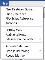
The Help pull-down menu
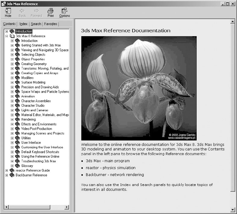
The 3ds Max User Reference
Now that you have completed this lesson, you should have a thorough understanding of how the UI components in 3ds Max work. You should be able to manipulate and configure the viewport area and use the command panel to create and manipulate simple objects. You should be able to view a simple animation and control its playback. Finally, you should understand how to manipulate the view of a model in the viewports.