
Transforms
In this lesson you will learn how to transform objects in a 3ds Max scene. You’ll use the transform commands to move, rotate, and scale objects, and you’ll learn about tools that assist you in using transform commands, namely coordinate systems and snaps. Finally, you will see how to use transform commands to model a scene.
After completing this lesson, you will be able to:
• Transform objects using the basic transform commands
• Use the Transform gizmos when you use basic transform commands
• Choose the different transform base points, and use them when transforming objects
• Use different coordinate systems.
• Apply snapping tools
• Use the Align tool
• Clone objects
• Mirror objects
• Understand some more advanced transform commands like Array, Spacing and Clone & Align.
You use basic transform tools in 3ds Max to move, rotate, and scale objects. Other tools you’ll see a little further on in this lesson essentially do the same thing, but with a different user interface that can automate several operations into one command. You’ll start with a look at the basic transform tools.
Move lets you position an object anywhere in a scene. You can move objects along a specific axis or plane, or freely. Move is useful when modeling and animating. You can move objects in the viewport using the Transform gizmo or the Transform Type-In.
Moving an object freely allows you to displace the object anywhere in 3D space.
The Move Transform gizmo appears at the pivot point location of an object. The gizmo allows you to restrict movement of the object by dragging an axis or a plane in the gizmo.
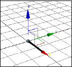
When using the Move tool, if you drag one of the three axes in the gizmo, movement is constrained to that direction. In this example movement is restricted to the X axis.
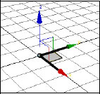
If you drag one of the rectangles in the gizmo, you restrict motion to a plane. In this example the XY plane was chosen, so the object cannot move in the Z direction.
Move Transform Type-In
In addition to the gizmo, the Move tool has a Transform Type-In dialog box that lets you enter the displacement numerically. When you right-click the Select And Move tool ![]() , the Transform Type-In dialog appears.
, the Transform Type-In dialog appears.
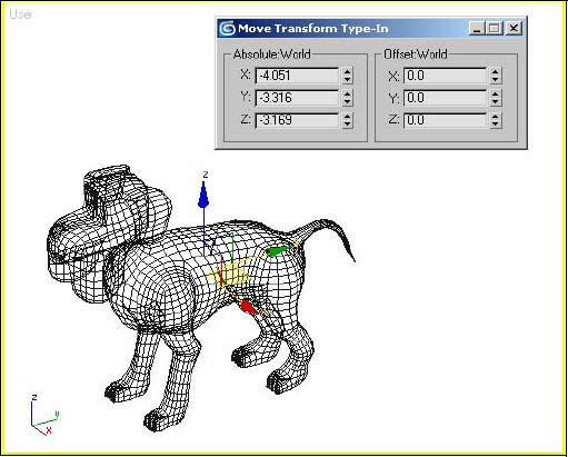
The Transform Type-In shows you the XYZ coordinates of the pivot point in the Absolute World group of the dialog, and allows you to adjust the position in this absolute format. The Offset group is for displacement relative to the object’s current position.
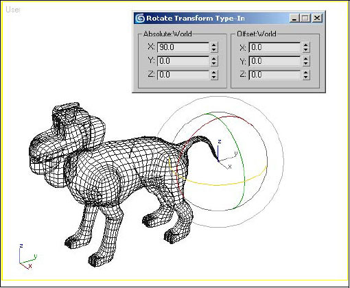
Rotating objects is another type of transform you use frequently when working with 3ds Max. The results you obtain depend greatly on the location of the point you rotate about and the axis of rotation. By default, the pivot point is used as the rotation center.
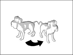
The dog has been rotated with its pivot point at its tail.
Rotate Transform Gizmo
The Rotate Transform gizmo appears at the pivot point location of an object. The gizmo comprises five circles. The Illustrations below describe the functions of these five circles.
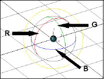
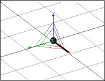
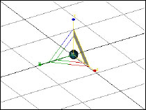
The XYZ axis rotation restrictions represented by the red, green, and blue circles. For example, if you click the red circle and drag, the object rotates about the X axis.

You can rotate the object freely by dragging the outer circle defined by the profile of the sphere. You can also do so by placing the cursor anywhere inside the gizmo but not on one of the concentric circles.
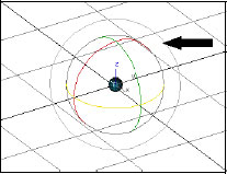
To restrict the rotation about a line perpendicular to the view plane, that is, the line of sight, drag the outer circle that is offset from the sphere.
Rotation Transform Type-In
In addition to the gizmo, the Rotate tool has a Transform Type-In dialog that lets you enter rotation values numerically.
As with the Move Transform Type-In, the Rotate Transform Type-In has absolute and offset (relative) methods of numerical entry.
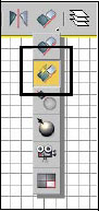
3ds provides three commands for scaling objects: Select And Uniform scale, Select And Non-uniform scale, and Scale And Squash. You’ll find all three operations on the Scale tool flyout on the main toolbar.
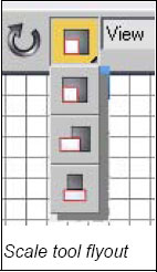
With Uniform scale, the first tool on the Scale flyout, all three dimensions of the object are scaled equally.
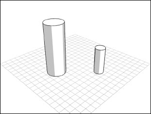
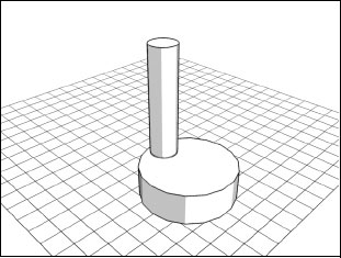
With Non-uniform Scale, the second tool in the scale flyout, you can scale one or two dimensions while the other remains constant. In the above illustration, the Z dimension of the cylinder has been scaled while X and Y have not changed.
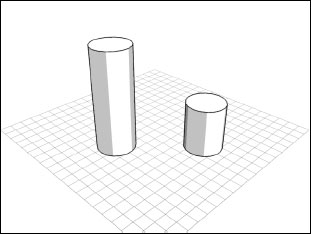
Scale And Squash, the third tool on the Scale tool flyout, lets you change one or two dimensions while the other axis or axes automatically adjust in the opposite direction. In the above illustration the Z axis has been scaled down while Scale And Squash increases the X and Y directions to compensate, with the result that the object’s original volume is maintained.
The Scale Transform gizmo appears at the pivot location of an object. You can use the gizmo to scale along one axis, on two axes, and uniformly.
When you drag one axis of the gizmo the object is scaled along that axis.
When you drag the plane between two axes as shown above, the object is scaled in that plane. In the above illustration the XZ plane was clicked with the result that scaling occurs on the X and Z axes.
When you drag the inner triangle, you scale on all three axes simultaneously.
In addition to the gizmo, the Scale tool has a Transform Type-In dialog that lets you enter Scale values numerically.

The Scale Transform Type-In provides absolute scale values that can be entered individually, thereby scaling the object disproportionately. The Offset value lets you to scale the object proportionally relative to its current size.
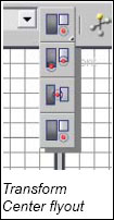
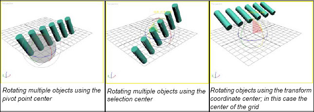
When you transform objects you have a choice of the base point. By default, scaling uses the pivot point of the object. Alternatively, you can use the selection center and the transform coordinate center. You set the mode with the Transform Center flyout.
Exercise 1: Simple Transform Exercise
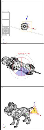
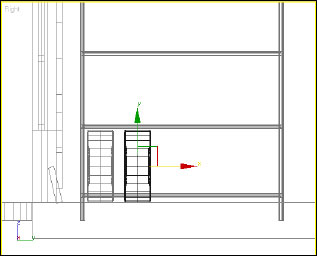
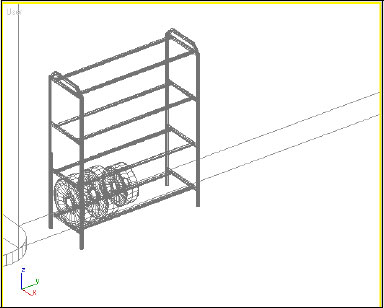
1. Open the file Empty Tire Rack.max.

The scene contains an empty tire rack and a single tire on the ground. You will place this tire on the rack and create a few more tires using transform tools.
2. Click Select And Rotate ![]() and then select the tire in the Right viewport.
and then select the tire in the Right viewport.
3. Press A on the keyboard to constrain rotations to five-degree increments. You will learn more about this feature later in the lesson.
4. Drag the inner circle of the Rotate transform gizmo to rotate the tire 90 degrees counterclockwise.
5. Click the Select And Move Icon ![]() and make the Front viewport active by right-clicking it.
and make the Front viewport active by right-clicking it.
6. Place your mouse cursor on the square in the Move transform gizmo and then drag to move the tire so that it sits on the rack.

7. Make the Right view active and move the tire to the left side of the rack by dragging the X-axis (red axis) of the Move transform gizmo.
8. With the Move tool still selected, press and hold the SHIFT key on your keyboard, click and hold on the X-axis of the Move transform gizmo, and drag approximately one-and-a-half tire widths to the right.
9. On the dialog that opens, choose the Copy option and enter 2 as the Number of Copies. Click OK to continue.

10. Click the Select And Scale icon ![]() in the main toolbar.
in the main toolbar.
11. In the Right viewport select the center tire and then drag the X-axis of the Scale gizmo and scale the tire to approximately 75% of its original size. Keep an eye on the status bar for reference.
12. In the User viewport select the rightmost tire. Drag near the center of the scale icon and scale the tire down to 80% of its original size.
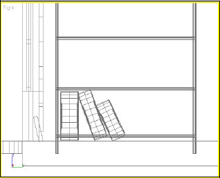
13. Use the Rotate tool to make the second and third tires lean toward the left.
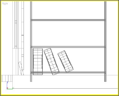
14. Finalize the placement of the tires with the Move tool.
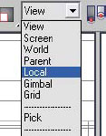
Eight coordinate systems are available in 3ds Max. In this section you will see some of the more common and useful systems. You change the current coordinate system using the Reference Coordinate System list on the Main Toolbar.
The World coordinate system is based on the XYZ axes in the 3ds Max workspace. The XY plane is the ground plane and the Z axis is perpendicular to this plane. The World coordinate system does not change, and is practical in that respect since you always know the orientation of the space around you.
The World coordinate system used as a reference. The Perspective viewport is active; note the orientation of the Move transform gizmo.

The World Coordinate system is still in use but now the Left viewport is active. Note that the orientation of the Move transform gizmo remains the same as when the Perspective viewport was active.
The View coordinate system is the default coordinate system used by 3ds Max. It is a coordinate system that adapts to the active viewport to keep the XY plane perpendicular to that viewport. This applies to isometric (2D) views only. If a 3D view such as the Perspective viewport is active, the View coordinate system behaves like the World coordinate system, where the XY plane lies flat on the ground and the Z-axis is vertical.
View coordinate system with the Perspective viewport active. Note the orientation of the Move transform gizmo.
View coordinate system with the Left viewport active. The orientation of the Move transform gizmo has changed.
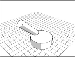
The Local coordinate system is based on the coordinate system of the object being transformed. An object’s local coordinate system follows rotation of the object.
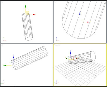
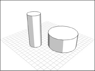
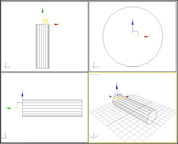
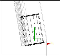
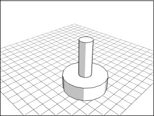
A freely rotated cylinder with the World coordinate system active.
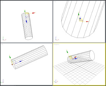
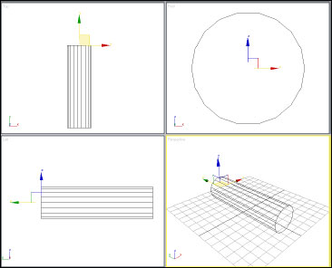
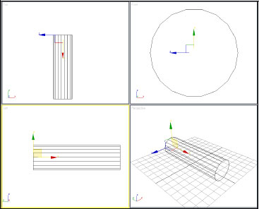
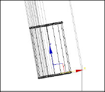
The Local coordinate system orients itself to the object. In this case the Z-axis of the coordinate system points along the height of the cylinder while the XY plane lies on the base.
The Pick Coordinate System is so called because it allows you to pick another object to use as a transform center. Once you choose Pick and then pick the object, the selection center must be set to Use Transform Coordinate Center.
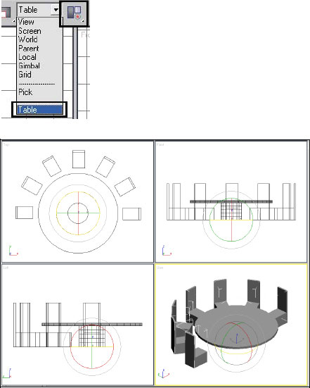
Pivot point of the (picked) Table object is used as the center of rotation when clones of the chair are created.
Four different snapping types are available in 3ds Max.
• Object Snaps: allow you to snap to grids and parts of objects such as vertices and midpoint of edges
• Angle Snap: limits rotation increments to a fixed number of degrees
• Percent Snap: used with the Scale tool to control the percentage of scaling of objects
• Spinner Snap: sets the single-click increment/decrement value for all spinners.
Object snaps can be useful when you are laying objects out along a grid or tracing an existing object and wish to snap to the object’s vertices. When you right-click the Snaps Toggle button on the main toolbar, the Grid And Snap Settings dialog opens. Note that this doesn’t turn on snapping; it simply lets you adjust the settings.
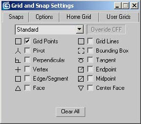
Grid Points is on by default.
When you click the Snaps Toggle button ![]() , the active options in the snap dialog are used. You can also enable snap mode using the keyboard shortcut S.
, the active options in the snap dialog are used. You can also enable snap mode using the keyboard shortcut S.
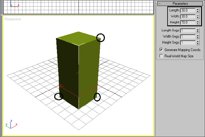
If Grid Points snapping is on when you create a box, each point of the base lands on a grid intersection, and the height is restricted to the grid spacing.
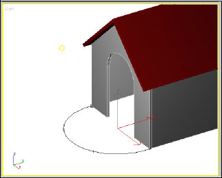
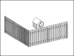
If you turn on Vertex snapping, you can position new geometry accurately using the vertices of existing geometry in the scene; in this case, the vertices at the corners of the dog house.
When you wish to rotate an object precisely without the use of the Rotate type-in, Angle Snap is quite useful. Angle Snap restricts the rotation of an object to a predetermined angle increment. Right-clicking the Angle Snap Toggle ![]() opens the Grid And Snaps Settings dialog with the Options panel active.
opens the Grid And Snaps Settings dialog with the Options panel active.
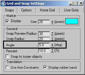
The Angle Snap value is controlled by the Angle value in the General group. The default setting of 5.0 is useful for most situations.
To turn on Angle Snap, click the Angle Snap Toggle ![]() and the button turns yellow, indicating the mode is active. You can also use the keyboard shortcut A.
and the button turns yellow, indicating the mode is active. You can also use the keyboard shortcut A.
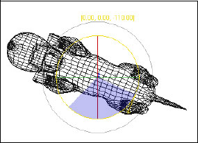
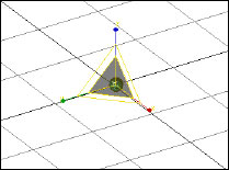
The Angle Snap restriction of rotation is made clear with XYZ rotation values appearing outside the Rotation Gizmo.
Percent Snap controls how the Scale value. Percent Snap is less commonly used and works in much the same fashion as Angle Snap. The Percent Snap Toggle ![]() activates the mode and right-clicking the button brings you to the same dialog panel as Angle Snap.
activates the mode and right-clicking the button brings you to the same dialog panel as Angle Snap.
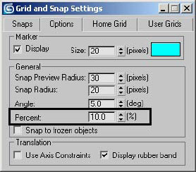
The Percent value controls the Percent Snap mode.
Exercise 2: Transforms using Snaps and Coordinate Systems
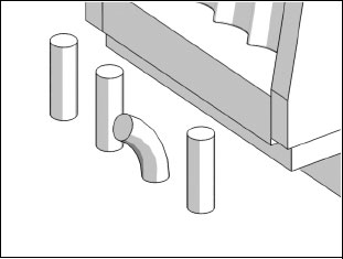
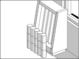
1. Open the file Oil Can Rack.max.
2. Click the Select And Move tool ![]() and in the Left viewport select the Oil Can object.
and in the Left viewport select the Oil Can object.
3. Click the rectangle in the Move transform gizmo.
4. Drag the Oil Can to the lower edge of the oil can rack.

5. ![]() Turn on the Angle Snap Toggle.
Turn on the Angle Snap Toggle.
6. ![]() Click the Select And Rotate tool.
Click the Select And Rotate tool.
7. Click the inner circle of the Rotate transform gizmo.
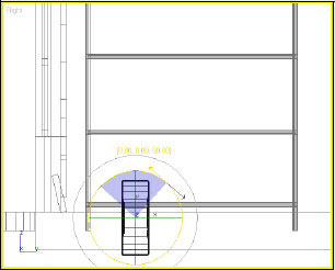
8. Rotate the Oil Can 10 degrees counterclockwise. Because Angle Snap is on and defaults to 5 degrees, this should be easy.
9. Zoom in to the Oil Can in the Left viewport.
10. Click the Select And Move button.
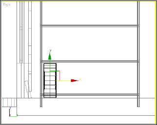
Note the Oil Can is not exactly positioned properly and the Transform gizmo is not well oriented to help.
11. From the Reference Coordinate System drop-down list, choose Local.
12. Now that the Transform gizmo is oriented to the local coordinate system of the Oil Can, drag the Y axis to move the can up and down, and the X axis to move left and right. This should make it easy to get the Oil Can in the proper location.
Exercise 3: Transforms with the Pick Coordinate System
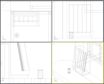
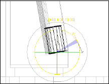
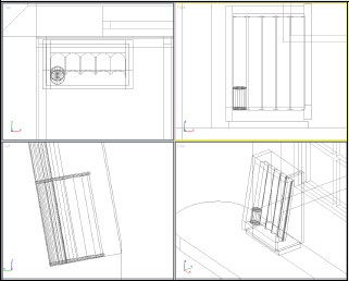
1. Open the file Tire Rack.max.
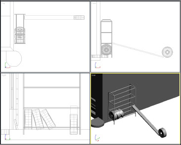
In the Tire Rack scene a ramp has been constructed to facilitate the placement of tires on the rack. You want to be able to make the tire follow the angle of the ramp.
2. Select the Tire To Move object.
3. Click the Select And Move tool ![]() .
.
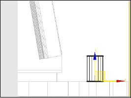
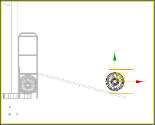
4. Right-click in the Front viewport to make it active.
5. Try to move the tire up the ramp. It’s a bit difficult because the tire does not follow the angle of the ramp.
6. Right-click to cancel the operation, or undo any movement if necessary.
7. Make sure the Move tool is still active and the tire object is still selected.
8. From the Reference Coordinate System drop-down list, choose the Pick option.
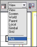
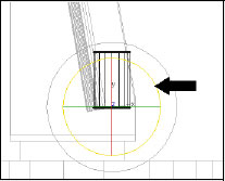
9. Click the Ramp object.

The tire’s Move transform gizmo now aligns with the Ramp object.
10. Move the tire along the ramp.
This is greatly facilitated by using the coordinate system of the ramp.
The Align Tool lets you line up a selected object, called the source object, with the position of a target object. You can also use Align to match a source object’s orientation to that of a target object. The Align tool is accessed from the Align button ![]() on the main toolbar.
on the main toolbar.
When you use Align to reposition an object in XYZ, you can use one of four different alignment options: Minimum, Center, Pivot Point, and Maximum. You can apply this setting separately to the current and target objects on any combination of axes. For example, take the two objects shown below:

Using Align on these objects can yield a variety of results.
This is a simple application of Align where the pivot points are aligned.

This is a more complex application of Align. On the X axis, the pivot points were aligned; on the Y axis the maximum positions of the objects were aligned, and on the Z axis the minimum of the source object was aligned with the maximum of the target object.
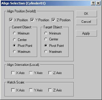
If two objects are not properly aligned with respect to one or more axes, the Align Orientation group of the Align dialog lets you adjust the source’s object orientation to match the target’s.

The Align Orientation group on the Align dialog
The two cylinders are oriented in different directions. The Z axes are not aligned.
Aligning the tilted cylinder to the base’s Z axis produces the illustrated result. It is important to note that Align Orientation does not displace the object in space.
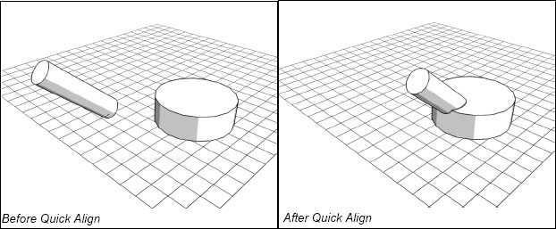
The Align flyout on the main toolbar provides a number of tools for different types of alignment. One such tool is Quick Align, the second icon on the flyout.
Quick Align works on the positions of the two objects’ pivot points. It does not affect orientation.
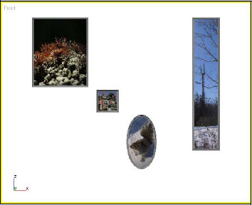
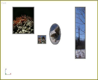
In this exercise you will provide a bit more order to the layout of some pictures.
1. Open the file Pictures01.max.

2. Select the Tall Frame object on the right.
3. Click the Align button ![]() on the main toolbar.
on the main toolbar.
4. Click the Regular Frame object on the left side.
5. On the dialog that opens, make sure only Y Position is on (turn off X and Y Position if necessary), set both Current Object and Target Object to Maximum, and then click OK to exit the dialog.
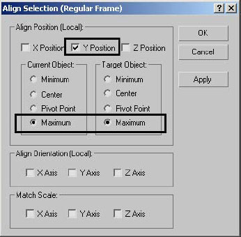
Because you aligned the maximum values on the Y axis, the top edge of the Tall and Regular frames are now at the same level.
6. Select the Elliptical Frame object and then click the Align Tool ![]() .
.
7. Select the Regular Frame, on the left.
8. On the Align Selection dialog that opens, make sure only Y Position is on.
9. Set Current Object to Center and Target Object to Minimum, and then click OK to close the dialog.
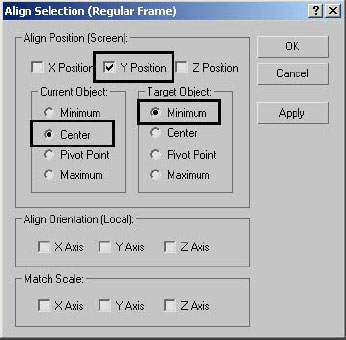
The Elliptical Frame is now centered on the bottom edge of the Regular frame.
10. Select the Small Frame object and then click the Align Tool ![]() .
.
11. Click the Regular Frame object.
12. In the Align Position group, turn on X Position only, set both Current Object and Target Object to Minimum, then click OK to close the dialog.
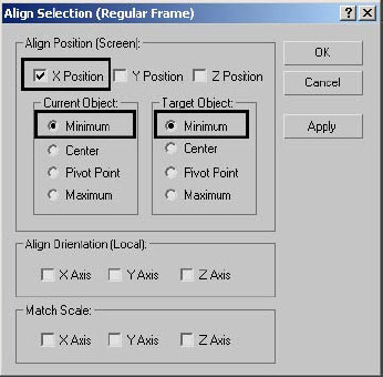
The Small Frame object is now left aligned with the Regular Frame object.

13. Make sure the Small Frame object is still selected, and then click the Align Tool ![]() .
.
14. Click the Tall Frame object.
15. On the Align Selection dialog, turn on Y position only and set both Current Object and Target Object to Minimum. Click OK to exit the dialog.
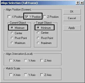
The picture frame layout is complete.
You use cloning to duplicate objects. One way to clone an object is to hold down the SHIFT key while moving, rotating, or scaling an object. Another is the Clone Selection command on the Edit menu. In 3ds Max you can create a clone in one of three states: Copy, Instance, or Reference. The differences are explained below.
The behavior of cloned objects when modified differs depending on which clone option is chosen.
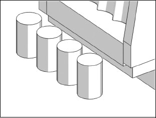
When you make copies of objects the new objects and the source objects are completely independent of one another.

Objects that are copied when cloned have complete independence. In the above illustration, each cylinder’s Radius and Height values were adjusted affecting the others.
When you choose to instance objects as you clone them, all the objects are linked together. Any change to one is reflected in the others.
Objects that are instanced when cloned have complete dependence on one another. If you change the Height or Radius value of one cylinder, the others change as well.
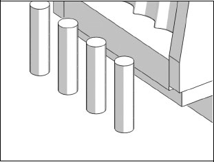
When you choose to reference objects as you clone them, you create a link between objects that allows some flexibility in the cloned objects.
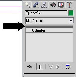
Objects that are cloned with the Reference option display a grey horizontal bar in the modifier stack, in this case just above the cylinder.
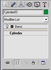
Modifiers applied when the grey bar is highlighted appear above the bar and are unique to that object.
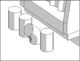
In this case a Bend modifier is added to one of the cloned cylinders.
Modifications to the base object or modifiers applied below the grey bar will affect all objects. In this case the radius of the initial cylinder has been changed.
When you are working with instanced and referenced objects and you want to make a duplicate independent of the others again, you can use the Make Unique tool found on the Modify panel. Make Unique converts an instance or reference to a copy.
When you work with instance and reference objects you might want to know which objects in your scene are dependent. You can check dependencies by using a check box on the Select Objects dialog.
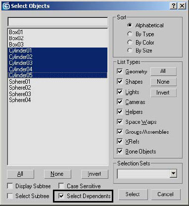
When Select Dependents is on, clicking any of the instanced cylinders highlights all of them.
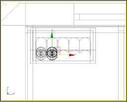
1. Open the file Oil Can Rack 01.max.
Using instanced clones, you will make a series of oil cans that are modifiable together.
2. Select the Oil Can object in the Top viewport.
3. ![]() Click the Select And Move tool.
Click the Select And Move tool.
4. SHIFT-drag on the red (X-axis) arrow of the Move transform gizmo. Make the first clone touch the original object.
5. On the dialog that opens, choose Instance and set Number Of Copies to 4.
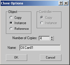
6. Click OK to exit the dialog.
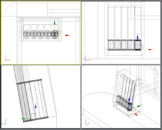
You should now have five instanced clones of the Oil Can Object along the bottom.
7. Select any one of the Oil Can objects.
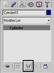
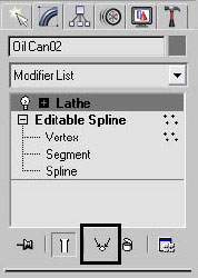
8. On the Modify panel, note the modifier stack of the Oil Can object. The Lathe modifier should be highlighted.
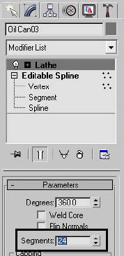
9. On the Parameters rollout, change the Segments value to 24. Note that the number of lines that controls the level of detail of the oil cans increases for all of the cans.
10. Select the center oil can.
11. Click the Make Unique button.
12. Change the Segments value to 12.

Only the center oil can is affected. Make Unique has made this oil can independent, like a copy.
13. Click the Select By Name tool ![]() .
.
14. Turn on Select Dependents.
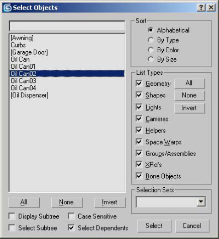
15. Click Oil Can02. It should remain the only object highlighted.
16. Click Oil Can03. The remaining Instanced clones become highlighted.
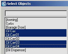
Only the remaining instances are dependent.
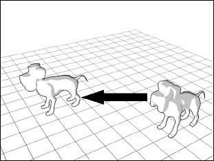
The Mirror transform takes an object and creates a symmetrical object along a mirror plane. You can choose to mirror about a number of different axes.
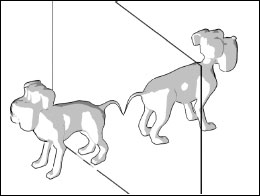
The Mirror tool creates a symmetrical object like that seen in a mirror.
The Array tool makes multiple clones of objects in the X, Y, or Z direction. In more complex applications you can use it to create multiple copies when you rotate and scale objects. You can find the Array tool in the Tools menu.
Array can create multiple copies of objects based on displacement, rotation, or scaling.
The Spacing tool allows you to create multiple objects along a spline object. The objects can be separated based on distance or number of copies along the spline. The Spacing tool can be found in the Tools menu.
Creating a regularly spaced object, like a picket fence, is easily accomplished with the spacing tool.
The Clone And Align tool lets you distribute source objects to a selection of destination objects. For example, you can populate several rooms simultaneously with the same furniture arrangement by replacing 2D temporary symbols with 3D chair objects.

Temporary 2D symbols are placed around the dinner table as placeholders for the Clone And Align tool. This is done so the scene is less geometrically heavy (that is, it contains fewer polygons), potentially speeding up viewport interaction.

After the Clone And Align tool is applied, the 3D chairs are distributed around the table.
In this lesson, you have learned how to use a number of transform tools and utilities. You have seen how to use the basic transforms and the Transform gizmo. You also saw how to use different transform base points, and coordinate systems. You also used snapping tools to assist in the creation and transform of objects. You saw how to clone objects and use the different clone options. Finally you learned about a few advanced transform tools for further study.