
Overview Lab
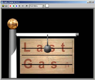
In this overview lesson, you will explore the basic creation, modification, and animation tools available in 3ds Max. You’ll open an existing scene, The “Last Gasp” Gas Station, and add a signpost to it. You will then animate the sign as if one of the chains holding the sign has broken and the sign is swaying in the air. To see where you should be at the end of this lesson, play the file
Sign Breaking.avi.
After completing this lesson, you will be able to:
• Create objects.
• Create and add materials to objects.
• Create lights.
• Create a simple animation.
• Render your animation to a movie file.
• Understand the overall workflow of an animation.
Exercise 1: Creating the Signpost
In this section, you start the geometric creation process. If you have not already done so, play the file Sign Breaking.avi to see the goal of this exercise.
1. Open the file Sign Breaking.max. You’ll add a cylinder to use as a signpost to this scene.
2. Right-click in the Top viewport to make the viewport active.
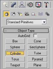
3. Click the command panel > Create panel > Geometry button, and then click the Cylinder button.
4. In the Top viewport, click and drag the center and radius of the cylinder on top of the circular object. Make it slightly smaller than the existing object.
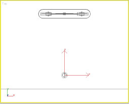
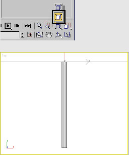
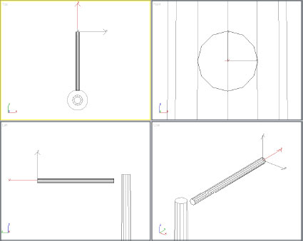
5. Release the mouse button to set the radius of the base of the cylinder. Move your mouse to adjust the height, and then click anywhere to set it.
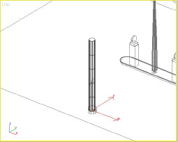
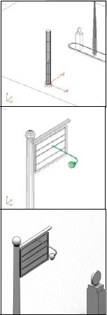
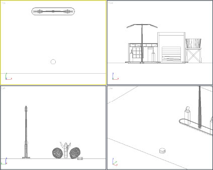
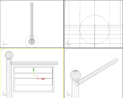
The User viewport shows the height more clearly.
Don’t be concerned about the size of the object. You’ll adjust it with the Modify panel controls. You can make changes on the Create Panel; however, it is recommended that you use the Modify panel to do so.
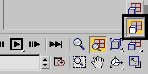
6. ![]() On the command panel, click the Modify tab.
On the command panel, click the Modify tab.
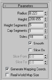
The Modify panel appears, showing the parameters of the selected object.
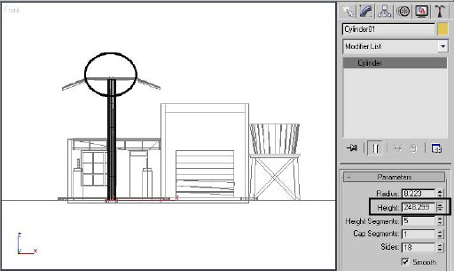
7. Drag the spinner next to the Height value up or down until the height of the selected signpost matches the existing light post in the scene. Keep an eye on the Front viewport for reference.
8. Use the spinner next to the Radius value to change the radius to 8 or 9 units.
9. Right-click the spinner next to Height Segments.
Note: Right-clicking a spinner normally sets it to 0. In this case, it is set to the minimum value of 1.
10. Click the Sides field, and then enter a value of 12.
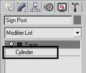
11. Give the object a proper name by clicking the name field on the Modify panel (it should read Cylinder01). Change the name to
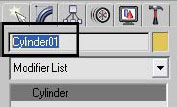
13. On the Modify panel, click the Modifier List to open the list of available modifiers, and then scroll down the list to the Taper modifier entry.
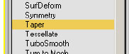
The Taper modifier is near the bottom of the long list of modifiers. By default, the modifiers are listed in alphabetical order.
14. Click the Taper modifier.
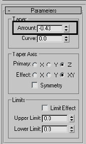
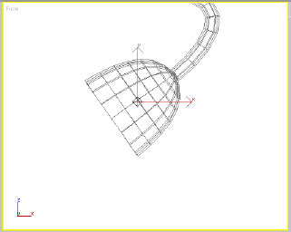
15. On the Parameters rollout adjust the Amount value so the signpost is smaller at the top. A value of –0.4 to –0.5 works well.
16. Return to the Cylinder level of the modifier stack by highlighting its entry in the list.
17. Change the Radius of the cylinder to 6.
18. Go back to the Taper entry in the modifier stack.
19. Change the Amount value to –0.35
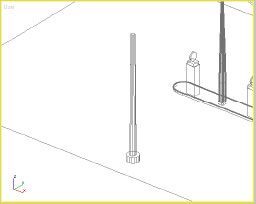
The completed signpost
You can see that 3ds Max provides considerable flexibility when you model. You can often go back and change sizes and values of modifiers to achieve the result you want.
Exercise 2: Adding Modeling Elements to the Signpost
In this next section, you’ll continue modeling some geometric elements for the signpost structure. You’ll need to create objects, move them into place, and make some modifications to them.
1. Continue with your previous file or open the file Sign Breaking_01.max.
2. In the Front viewport, zoom into the top of the signpost.
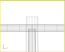
The top of the signpost appears with more geometry in the background.
3. Select the horizontal element.
4. Right-click, and from the menu, choose Hide Selection.
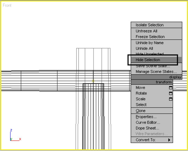
Hiding objects removes them from the display temporarily, making it easier to work in that area.
5. On the Create panel, in the Geometry category, click the Cylinder button.
6. In the Front viewport create a cylinder with a base radius of about 2 to 3 units near the top of the signpost.
7. Move the mouse and then click to set the height to any value.
8. ![]() Go to the Modify panel.
Go to the Modify panel.
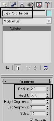
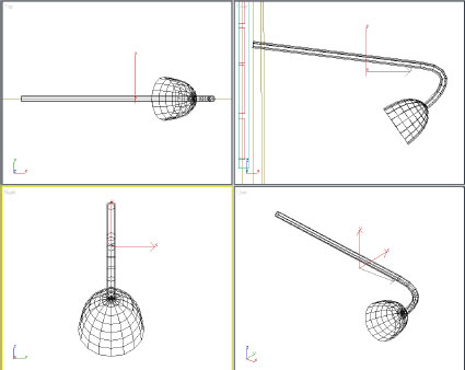
9. Change the name of the object to Sign Post Hanger.
10. Change the Radius to 2 units and the height to 60.
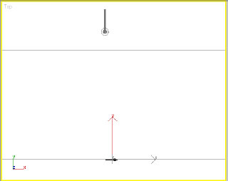
11. You cannot see the object in any of the viewports because the construction plane of the Front viewport is outside the viewing area of the other viewports.
12. With the new object still selected, right-click in the Top viewport to make it active.
13. In the view controls, click and hold on the Zoom Extents button, and then from the flyout choose Zoom Extents Selected.
Zoom Extents Selected frames the selected object in the active viewport.
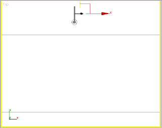
14. ![]() Use the zoom command or your mouse wheel to slowly zoom out of the Top view.
Use the zoom command or your mouse wheel to slowly zoom out of the Top view.
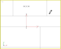
As you zoom out you should start recognizing some familiar objects.
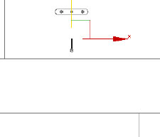
15. ![]() On the Main Toolbar, click the Select And Move Tool.
On the Main Toolbar, click the Select And Move Tool.
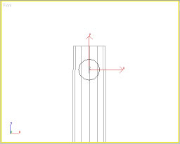
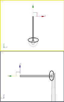
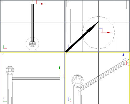
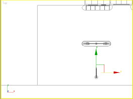
16. Drag the green vertical arrow upward till the cylinder moves close to the signpost.
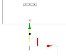
Clicking on the green arrow restricts movement to the Y-axis direction only.
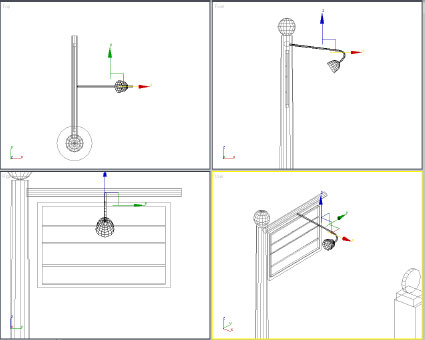
The desired end result is shown in the above illustration.
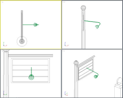
17. In the view controls, click Zoom Extents All Selected.
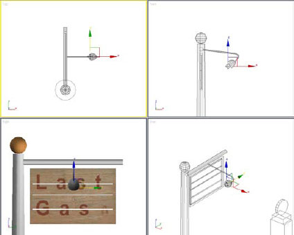
18. Use Zoom All to zoom out slightly on all four views at once.
All four views show a clear view of the signpost structure.
19. ![]() If it is not already active, click Select And Move.
If it is not already active, click Select And Move.
20. In the Top viewport, move the cylinder until it clearly intersects the top of the signpost.
Check the intersections, particularly in the Left viewport. It’s better to intersect slightly than not at all. In the Top viewport, it might look as though you are intersecting the post at the top, while in fact you are intersecting it at the bottom. Remember the post has been tapered.
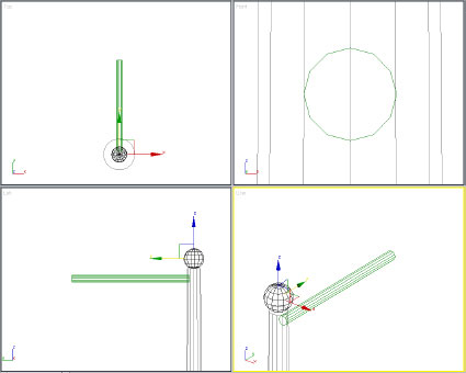
21. In the Top viewport, create a sphere of approximately 6 units in radius, centered on the pole of the signpost you created earlier.
22. Go to the Modify panel.
23. Set the Radius to 6 units, and the Segments value to 16.
24. Change the object name to Sign Post Sphere.
25. Zoom out to get a better look at the scene. In either the left or the front view, move the sphere up until it is resting on top of the pole.
Exercise 3: Adding More Components: Creating the Sign
In this next section you will create the sign itself. You will model in some cases from 2D splines and in other cases directly in 3D.
1. Continue with your previous file or open the file Sign Breaking_02.max.
2. Right-click the Left viewport to make it active.
3. Right-click the viewport label in the top-left corner and choose Views > Right.

4. Enlarge the Right viewport by moving the center of the viewports to the upper right.
5. Use the Pan tool ![]() to pan the view so there is plenty of room below the signpost structure.
to pan the view so there is plenty of room below the signpost structure.
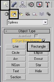
6. On the Create panel, click the Shapes button, and then click Rectangle.
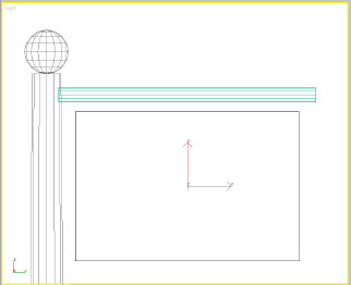
7. Drag out a rectangle approximately 60 units wide and 40 units in height. Position it as shown.
8. On the Object Type rollout, click the Start New Shape check box to turn it off.
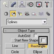
When Start New Shape is off, new splines you create become part of the selected shape, and are treated as a single object.
9. Drag another rectangle inside the first one to create a frame.
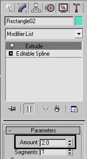
10. Go to the Modify panel, and from the Modifiers List choose the Extrude modifier.
11. Use the spinners to set the Amount value to 2.0.
12. Press the F3 function key. The Right viewport is now shaded.
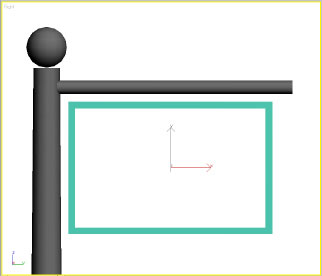
Because the two splines were created as one shape, extruding the object creates a frame rather then one box inside another.
13. Press the F3 function key again; the Right viewport returns to Wireframe display.
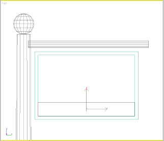
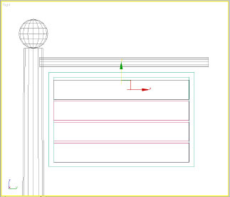
14. On the Create panel, click the Geometry button and then click Box.
15. Create a box along the bottom of the frame approximately 8 units in Length and 1 unit in Height. Use the Modify panel to adjust the box size if necessary.
16. On the main toolbar click the Select And Move Tool ![]() .
.
17. Hold the Shift key down and click and drag the green vertical arrow up to a position with a small gap between one plank and the other.
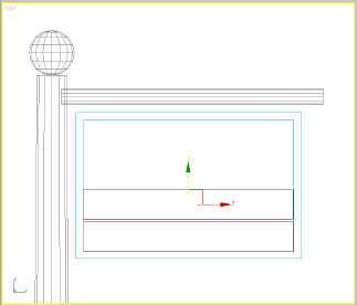
The Shift+Move operation creates a clone of the original object.
18. On the Clone Options dialog set Number Of Copies to 3, and make sure the Object option is set to Copy.

19. Click OK. Your scene should now look similar to the illustration.
You’ll introduce some randomness to the sign planks by moving them and adjusting their sizes.
20. Make sure the upper plank (Box04) is selected.
21. Go to the Modify panel and change the Length to 8.5.
22. Move the upper plank so it reaches the underside of the upper part of the frame.
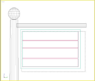
23. Continue to introduce randomness to the sign by changing values and position of the planks. Your scene should look something like the illustration.

24. Region-select all the objects in the sign.
To region-select with a crossing region (the default method), click in an empty part of the viewport and then drag across the objects to select.
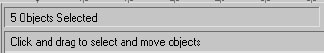
25. Check the status line. It should tell you that there are five objects selected.
26. On the menu bar, from the Group menu, choose the Group command.
27. On the dialog that appears, name the group Sign and then click OK.
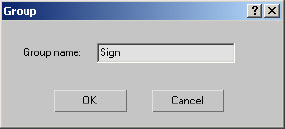
A group is a collection of objects and needs to be named; giving a group a descriptive name helps you to remember its purpose.
The sign is complete but has been created on the construction plan of the Right viewport. You need to find it and position it correctly.
28. Right-click a splitter bar between viewports.
29. Choose Reset Layout from the menu that appears.
30. Using the Zoom tool ![]() , slowly zoom out of the Top viewport until you see the sign on the left side.
, slowly zoom out of the Top viewport until you see the sign on the left side.

Unless you accidentally deselected the group, the Sign group will have the transformation axis on it, making it easier to locate visually.
31. Right-click to exit the Zoom tool and return to Select And Move, and then drag the red arrow to move the Sign group as close to the signpost as possible.
32. Right-click the Front viewport, and then zoom out enough to see the Sign group.
33. Make some final adjustments to center the Sign group on the Sign Post Hanger object.
Exercise 4: Merging a Sign Lamp: Merging an Object from Another File
In this next section you will bring in an object from another file into the current scene. Frequently, modelers save objects that they use repeatedly into a library and then merge them into a scene that they are working on.
1. Continue with your previous file or open the file Sign Breaking_03.max.
2. On the menu bar choose File > Merge.
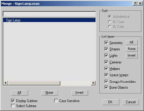
3. Use the Merge File dialog to locate your lesson directory and select the file Sign Lamp.max, and then click Open.
4. Highlight the Sign Lamp object on the Merge dialog and click OK.
5. Click Zoom Extents All Selected ![]() .
.
6. Zoom out of the Top viewport until you find the signpost.
7. Use the Move tool to position the lamp roughly in the center of the Lamp Pole.
8. Click Zoom Extents All Selected ![]() .
.
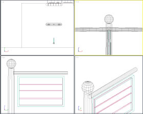
9. Use Zoom All ![]() to zoom out about 60–70% on all viewports.
to zoom out about 60–70% on all viewports.
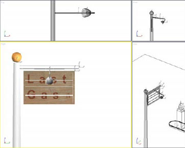
10. Use the Move tool to position the Sign Lamp object as shown.
Exercise 5: Adding Basic Materials to the Signpost
In this section, you will create materials and apply them to the objects you have created in this scene. Materials allow you to change the default appearance of an object, and can make 3D computer objects photorealistic.
1. Continue with your previous file or open the file Sign Breaking_04.max.
2. Activate the Right viewport and press F3 to set its rendering mode to Smooth + Highlights.
3. On the main toolbar click the Material Editor ![]() button.
button.
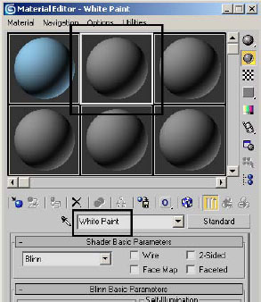
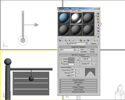
4. Click the second sample sphere to make it active.
5. Change the name to White Paint.
6. On the Blinn Basic Parameters rollout, click the gray Diffuse color swatch and change the Value setting to approximately 230. This makes the material off-white.
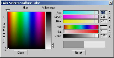
7. Close the Color Selector dialog.
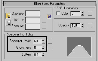
8. On the Blinn Basic Parameters rollout of the Material Editor change Specular Level to 60 and Glossiness to 5. This makes the material shinier.
9. Position the Material Editor dialog so that you can see the Right viewport.
10. Use the Select tool ![]() to select the Sign Post object. With the CTRL key depressed, also select Sign Post Hanger and Sign Lamp.
to select the Sign Post object. With the CTRL key depressed, also select Sign Post Hanger and Sign Lamp.
11. Click the Assign Material To Selection button. This assigns the White Paint material to the selected objects.
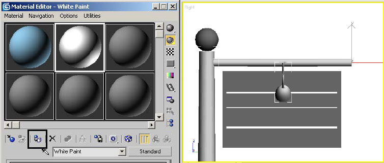
The material is applied to the three selected objects.
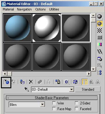
12. Click the third sample sphere in the top row.
13. Click the Get Material button.
14. On the Material/Map Browser dialog that opens, choose Browse From > Mtl Library.
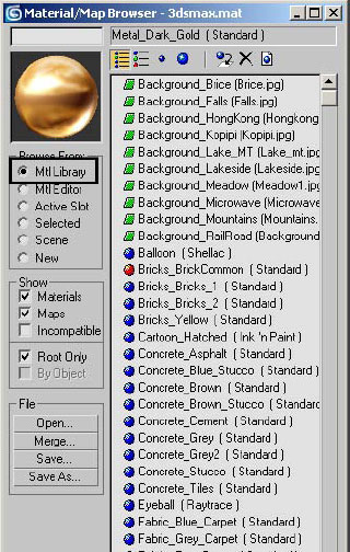
15. Scroll down the list of materials until you reach a group of materials that start with the word Metal.
16. Click the Metal_Dark_Gold material. The Material/Map Browser thumbnail window displays a sample of this material.
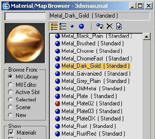
The Material/Map Browser provides a wealth of predefined materials. You can find even more by opening other material libraries.
17. Double-click the Metal_Dark_Gold material. This brings the material into the Material Editor and makes the Material Editor dialog active.
18. Drag the Metal_Dark_Gold sample sphere to the Sign Post Sphere object. This applies the material to the object.
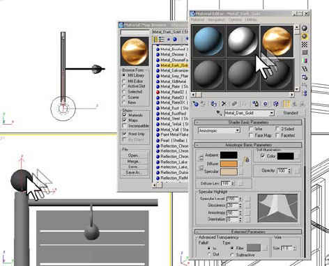
19. Close the Material/Map Browser.
Exercise 6: Adjusting Ambient Lighting and Adding Lighting for the Sign
In this section, you will reduce the amount of ambient lighting in the scene and add some lighting to enhance the illumination of the sign. This makes the lighting more consistent with a twilight scene.
1. Open the file Sign Breaking_05.max. Do not continue with the previous file.
2. Make sure the Right viewport is active.
3. On the main toolbar, click the Quick Render Button ![]() .
.
This rendering gives you an idea how the lighting looks in the scene currently.
4. Dismiss the Rendered Frame Window.
5. From the Tools menu choose the Light Lister command.
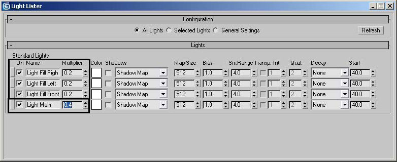
6. Change the Multiplier values for the Light Fill lights to 0.2, and for the Light Main value to 0.4.
7. Dismiss the dialog. The lighting in the scene is now considerably darker.
8. On the main toolbar, click the Quick Render Button ![]() .
.
The rendering is considerably darker.
9. Dismiss the Rendered Frame Window.
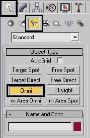
10. Go to the Create panel and click the Lights button and then the Omni button.
11. In the Front viewport, click a point inside the lamp to place an Omni light just inside the Sign Lamp object.
12. In the Top viewport, adjust the zoom level so that you can see the signpost structure and the new Omni light.

As with geometric objects, lights are added on the construction plane. In this case the light is not where it should be in the Top viewport and will need to be moved.
13. Click the Select And Move tool ![]() .
.
14. Move the Omni light close to the Sign Lamp object in the Top viewport. If necessary, zoom in to make it easier to center the light.
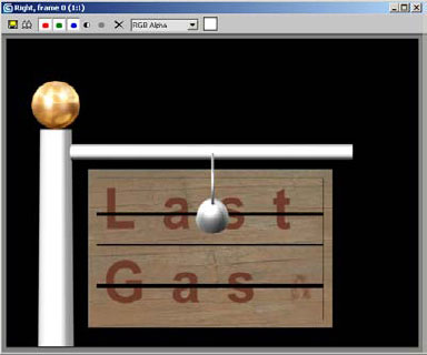
15. Make the Right viewport active and then click the Quick Render Button ![]() .
.
The sign appears to be mostly illuminated from the new Omni light.
16. Dismiss the dialog.
17. Go to the Modify panel and change the name of the Omni01 light to Sign Lamp Light.
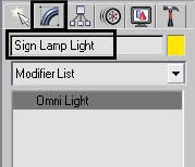
It is always important to remember to name your objects; otherwise a scene can be difficult to decipher.
Exercise 7: Adding the Broken Sign Animation: Animating the sign breaking
In this section you will animate the action of the sign breaking and swinging on a single chain.
1. Open the file Sign Breaking_06.max. Do not continue with your previous scene.
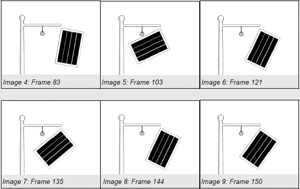
The images that follow depict the desired motion of the sign. A sequence of images like this to show how an animation should proceed is called a storyboard.
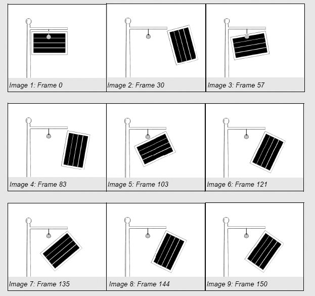
You will need to create a keyframe at each of the indicated positions.
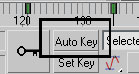
2. Click the Auto Key button near the bottom of the 3ds Max window.
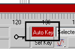
When Auto Key is active, the border of the active viewport turns red, reminding you that changes that you make while in this mode cause the software to record changes and create keyframes.
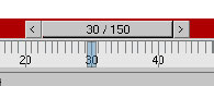
3. Move the time slider to frame 30.
4. On the main toolbar click the Select And Rotate tool ![]() .
.
5. Click the sign to select it.
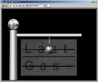
6. In the Right viewport a circular element appears. Drag the outer circle and rotate the sign to the angle shown in Image 2, below.
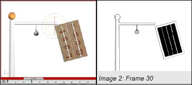
Note the keys created on the timeline at 0 and 30.
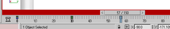
7. Move the time slider to frame 57.
8. Rotate the sign back to a position as indicated in the following image.
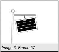
9. Note the creation of a new key at frame 57.
10. Repeat this process for the remainder of the images illustrated.
11. Click the Auto Key button to turn off Auto Key mode.
Always remember to turn off Auto Key mode when you are done creating animation of a part or scene. If you leave Auto Key mode on, you could accidentally create animation when you do not want to.
12. Go to frame 0 and click the Play button ![]() to see your animation.
to see your animation.
Exercise 8: Rendering your animation
In this final section you will render your animation to a movie file.
1. Continue with your previous scene or open the file Sign Breaking_07.max.
2. Click in the Right viewport to make it active.
3. Click the Render Scene Dialog button ![]() on the main toolbar.
on the main toolbar.
4. Set Time Output to Active Time Segment.
5. Make sure Output Size is set to 640 x 480.
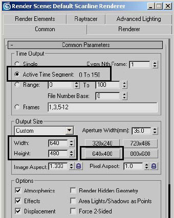
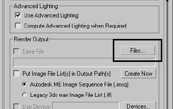
Scroll down the Render Scene dialog until you see the Render Output group.
6. Click the Files button.
7. Set Save As Type to AVI File (*.avi). Enter the file name Sign Breaking.
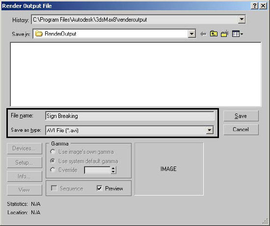
You can render the movie file in its default location or choose a different directory.
8. Click the Save Button.
9. The AVI File Compression Setup dialog opens. Click OK to accept the default settings.
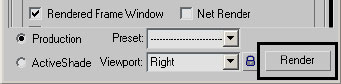
10. At the bottom right of the Render Scene dialog, click the Render button.
11. The rendered images display in the Rendered Frame Window.
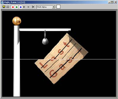
12. When the rendering is completed, dismiss the Rendered Frame Window.
13. From the File menu choose View Image File.
14. Click Sign Breaking.avi and then click the Open button.
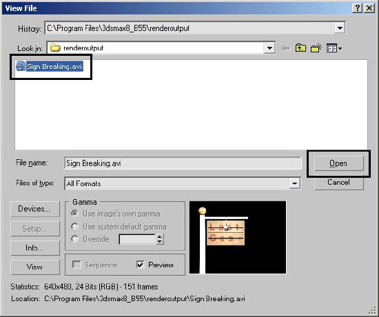
15. A Media Player window opens and plays the animation.
16. After the animation finishes playing, close the Media Player window.
17. Save the scene file as My Breaking Sign.max.
In this lesson you built some simple elements, embellished them with materials and proper lighting, and completed a simple animation. You should now understand the overall workflow of a simple project. You can create objects, materials, lights, and animation as well as make some adjustments to elements in the scene. Finally, you can now render your animation to a file for playback or distribution.