Chapter 5. MAC Basics
We must, indeed, all hang together, or most assuredly we shall all hang separately.
802.11n made several modifications to the MAC layer to improve efficiency. Just as jumbo frames on Ethernet improve efficiency by increasing the “timeslice” of medium usage devoted to transferring data, larger frames in 802.11n do the same. However, unlike Ethernet, frames in 802.11 must be acknowledged. When several frames are clustered together in an aggregate container, sending single positive acknowledgments for each would give back many of the efficiency gains. Therefore, 802.11n devices make extensive use of block acknowledgments to improve the efficiency of the required positive acknowledgment process; 802.11n receivers can selectively acknowledge the individual constituent frames inside an aggregate.
Frame Changes
The 802.11 data frame is only slightly changed by 802.11n. Figure 5-1 shows the format of an 802.11 Data frame as modified by 802.11n. The major changes from the traditional 802.11n Data frame are the increase in size, the addition of the optional HT Control subfield, and the fact that the QoS Control field is utilized extensively in block acknowledgment. The payload of the MAC is increased about fourfold, which can be used to aggregate higher-layer frames together for efficiency.

Management frames signal that they are part of an 802.11n network by including the HT Capabilities information element, shown in Figure 5-2. When a station includes the HT IE in transmissions, it is declaring that it is an 802.11n device. The HT IE is included in Beacon frames so that stations can determine that a network supports 802.11n. An 802.11 station will insert the HT IE into Probe Request frames to seek out 802.11n networks and declare to an AP that it is capable of 802.11n operation. The HT IE is also included in Association and Reassociation exchanges so that an 802.11n device associating to an AP can exchange information on capabilities.

- HT Capabilities Info (2 bytes)
The basic capability information is used to communicate the types of channels, coding, and coexistence support to reduce potential interference between neighboring networks using 20 and 40 MHz channels. One important bit in this field is the 40 MHz Intolerant bit, which is described in 40 MHz Intolerance for Channel Width Interoperability.
- A-MPDU Parameters (1 byte)
This field declares parameters used with A-MPDU aggregation, described in A-MPDU.
- Supported MCS Set (16 bytes)
This large field includes a great deal of information on the data rates supported by the station including the IE. It allows a station to report the data rates it can support, plus any difference between the data rates it can receive and the data rates it can transmit (though this protocol feature is not commonly used).
- HT Extended Capabilities (2 bytes)
This field supports the description of extended capabilities such as Phased Coexistence Operation (PCO) and the Reverse Direction (RD) protocol. Neither of these features are widely implemented, and are not described in this book.
- Transmit Beamforming Capabilities (4 bytes)
These fields support beamforming, which is a topic complex enough to receive its own section in Chapter 4.
- Antenna Selection Capabilities (1 byte)
Antenna selection capabilities are used in systems which have more antenna elements than radio chains. This is not a common configuration for devices, and thus, these bits are not widely used in shipping products.
The HT Operation IE, shown in Figure 5-3, is included in transmissions from the AP to inform client devices of the current state of the network. It is included in Beacon, Probe Response, and (Re)Association Response frames.

- Primary Channel (1 byte)
This field indicates the primary operating channel of the network. This is the channel number that will be used in management interfaces.
- Secondary Channel Offset (2 bits)
This field is set to 1 if the secondary channel has a higher frequency than the primary channel, 3 if the secondary channel is below the primary channel, and 0 when no secondary channel is present. Generally, most of the time, the secondary channel will be 20 MHz higher than the first channel; the secondary channel position is needed for coexistence mechanisms, as described in Channel Width Selection (20/40 MHz BSS).
- Channel width (1 bit)
This field is set to 0 when the channel is a “narrowband” 20 MHz channel, and 1 when it is any other value.
- RIFS (1 bit)
This field is set to 1 if RIFS operation is allowed, and 0 if it is forbidden. RIFS operation is discussed in more detail in the section Reduced Interfame Space (RIFS).
- HT Protection (2 bits)
This field indicates the type of protection being used to avoid interference with pre-11n devices. Protection is discussed in more detail in Protection of Non-HT Transmissions.
- Non-greenfield stations present (1 bit)
When an associated station is not capable of greenfield operation, this bit is set to 1.
- OBSS Non-HT STAs present (1 bit)
Indicates that an overlapping BSS (OBSS) has non-11n devices associated that require protection.
- Dual Beacon, Dual CTS, and STBC Beacon (1 bit each)
These modes are used when the Beacon is transmitted using Space-Time Block Coding (STBC), which is relatively uncommon because it may render the beacon unintelligible to non-STBC stations.
- L-SIG Protection Full Support (1 bit)
Set to 1 to indicate full support of the L-SIG protection mechanism described more fully in Protection of Non-HT Transmissions.
- PCO Active and PCO Phase (1 bit each)
These bits indicate the use of the Phased Coexistence (PCO) method, which switches a channel between 20 MHz and 40 MHz. These bits are used to indicate that PCO is in operation and whether the channel is currently 20 MHz or 40 MHz. PCO is not widely used, so this book does not describe it in detail.
- Basic MCS set (16 bytes)
This string of 127 bits is used to signal support of the various data rates, defined by a modulation and code set (MCS). Each of the 76 MCS rates is assigned a bit, starting from zero, and each bit is set to 1 if the data rate is supported. Unused bits are reserved and set to 0.
Airtime Efficiency Improvements
The core idea behind aggregation is that gaining access to the wireless medium in 802.11 is time consuming. By forming an aggregate frame, an 802.11 device can spend more time transmitting, and effectively spread the cost of gaining access to the medium over frames that carry several higher-layer packets. 802.11n defines two types of frames: the Aggregate MAC Protocol Data Unit (A-MPDU) and the Aggregate MAC Service Data Unit (A-MSDU). The two types of aggregation are distinguished by where in the protocol stack they apply aggregation.
Frame aggregation nicely illustrates one of my favorite truths about standards: they tell you how to do something, but not when or why. If you go looking in the 802.11 standard for an explanation of when to build an aggregate or how to manage a transmit queue, you won’t find it. It is up to individual product designers to build a queuing algorithm that makes appropriate choices on when to coalesce individual frames into an aggregate, and how to manage the size of aggregates so that large data frames don’t block small high-priority frames from voice traffic.[24]
A-MPDU
The more common form of aggregate frame, the A-MPDU, is shown in Figure 5-4. The A-MPDU is a relatively simple form of aggregation in that the higher-layer (IP) packet that would normally be transmitted is given a MAC header and sent back-to-back. In Figure 5-4(a), the IP packet is given a MAC header and trailer, and the (unaggregated) frame is put into a PHY-layer frame for transmission. In contrast, Figure 5-4(b) shows the aggregation process. Several IP packets are each given their own header. Because these individual packets in the aggregation process will be put together, they are referred to as A-MPDU subframes at this stage. In the aggregation process, the MAC Delimiter is inserted to assist a receiver in extracting individual subframes. Each subframe gets a complete 802.11 header, frame check sequence, and is padded so that it aligns on symbol boundaries in the physical transmission. Because each subframe in an A-MPDU gets its own MAC header, encryption is applied to each subframe in isolation. Because each subframe in an A-MPDU has its own frame check sequence, an error in one subframe will only affect that subframe, and other subframes in the aggregate can be recovered. All frames within an A-MPDU must be destined to the same receiver address on the wireless link, but may have multiple destination addresses.[25]

A-MPDU is widely supported, and typically uses hardware-assisted processing. The Wi-Fi Alliance 802.11n certification program requires support for reception of A-MPDU frames. Although A-MPDU is widely supported, it is not typically easy to tell from an analyzer that an A-MPDU has been transmitted. Many analyzers plug into the host protocol stack at a level at which the aggregate frame has already been separated out into its constituent subframes, and each of those subframes is made available to the analyzer separately. An A-MPDU is limited in size only by the 802.11n PLCP, and thus can be up to 65,535 bytes.
A-MPDU Density
Although many receivers can process aggregate frames, the performance of hardware designs can vary. Gaining access to the wireless medium is an expensive process, and even if it is necessary to insert padding in between A-MPDU subframes, the performance of a transmission can be improved dramatically over individual transmissions. A-MPDU size is limited both by the total size of an A-MPDU, as well as the time required between A-MPDU subframes. The acceptable values of A-MPDU timing parameters is shown in Table 5-1. In my unscientific experience, many devices are capable of 64 kB A-MPDU processing, even if they require 4 µs or 8 µs spacing between subframes.
A-MSDU
In addition to aggregation just before handing bits to the PHY for transmission, it is possible to pack multiple higher-layer packets into a single MAC frame. Building an Aggregate MSDU (A-MSDU) requires more software support because the network driver must take several higher-layer packets and build them into a single MAC frame payload.[26] The format of the A-MSDU, shown in Figure 5-5, shows how a higher-layer packet is put into an A-MSDU subframe, and those subframes are put together into a single MAC frame. In contrast to A-MPDU, this type of aggregation has only one MAC frame. As a result, when security is applied to an A-MSDU, one encryption operation secures the whole aggregate frame.

- Destination address (DA)
This field holds the destination MAC address of the subframe.
- Source address (SA)
This field holds the source MAC address of the subframe.
- Length
This field is the length of the MSDU in bytes.
- MSDU
Each individual constituent MSDU from higher layers appears after the destination/source/length triplet.
- Padding (0-3 bytes)
This field is computed so that the length of the A-MSDU subframe is an even multiple of 4 bytes.
An A-MSDU can have a maximum size of 7,955 bytes because all the aggregated frames must fit in the frame format shown in Figure 5-1.
The two forms of aggregation can be combined. Each of the A-MPDU subframes can itself be an A-MSDU, as shown in Figure 5-6. In the figure, the last subframe in the A-MPDU is itself an aggregate frame containing two MSDUs.

Aggregation Compared
The two methods of aggregation described in the previous sections are subtly different, and therefore, it is worth showing a comparison between the two. Table 5-2 compares A-MPDU and A-MSDU aggregation. Reception of both types of aggregate frames is widely supported, and about half of products support transmission of A-MPDUs.
| Attribute | A-MPDU | A-MSDU |
| Payload size | Very large - about 64 kB | Larger than standard 802.11 frames (about 8 kB) |
| Software support | Lower. Aggregation is performed by hardware interface and presented to the operating system as independent frames. | Higher. Software (generally driver software executing on host platform) must perform A-MSDU assembly and unpacking. |
| Transmission overhead | Higher. Each subframe has a complete MAC header and FCS. | Lower. Only one MAC header and FCS is required for the aggregate frame. |
| Transmission reliability and interference resistance | Higher. Each subframe has its own FCS and can be checked independently. Loss of a subframe only loses a single component of the aggregate. | Lower. If the FCS check fails, all subframes are discarded. |
| Frame encryption | Applied to each individual subframe. Each subframe must be decrypted individually. | Applied to the aggregate as a whole. Only one decryption is necessary to obtain all subframes. |
| QoS traffic classes | Multiple. One traffic class per subframe. | One traffic class for all subframes. |
| Reception support required? | Yes, and tested by Wi-Fi Alliance certification. | Yes, and tested by Wi-Fi Alliance certification. |
| Transmission support required? | No. Optional in both 802.11n and the Wi-Fi Alliance certification test. | No. Not tested by the Wi-Fi Alliance certification test. |
Block Acknowledgment
In the 802.11 MAC as it was originally specified in 1997, every frame required a positive acknowledgment. Each transmission was not complete until an acknowledgment was received. Network traffic is generally bursty. For example, a user reading web pages will send out a request, receive a flurry of packets carrying the requested web page, and then the network will generally be idle while the user reads the page. The original conception of the 802.11 MAC required that each frame sent to the receiver be acknowledged separately, as in Figure 5-7(a). The quality-of-service extensions in 802.11e brought in block acknowledgments (usually abbreviated as BlockACK), which allowed the sender to transmit a stream of frames and have them all acknowledged at once. Conceptually, the BlockACK extensions work similar to the selective ACK option in TCP. Two forms were defined in 802.11e, and subsequently carried over to 802.11n, and both are illustrated in Figure 5-7(b). With the Immediate Block ACK form, the sender transmits a series of frames and expects an acknowledgment right away, while in the Delayed Block ACK form, the receiver can send its acknowledgment later.

In Figure 5-7(b), the QoS Data frames are sent without any immediate positive acknowledgment. Instead of requiring that each frame be individually acknowledged, a single Block ACK frame exchange handles all acknowledgment. Because the Block ACK exchange is faster than individual acknowledgments, medium efficiency is improved. Block ACKs work by setting up a “window” for acknowledgment, and enable a receiver to selectively acknowledge any or all of the frames within a window. If any one of the three frames in Figure 5-7(b) are lost, the block acknowledgment can request retransmission of just the lost frame. For example, if the second data frame is lost, the Block ACK exchange will acknowledge the first and third frames.
Aggregate frames are well-suited for use with block ACKs because an aggregate frame holds several individual frames. By transmitting all the frames in the aggregate together, much less time is expended in the protocol overhead operations used to gain control of the channel. Block ACK processing was originally optional, but the efficiency gains possible when coupled with aggregate frame transmission are so compelling that Block ACK support is mandatory for 802.11n devices.
In addition to requiring support for Block ACKs, 802.11n defined new extensions to the protocol to reduce resource requirements for receivers of aggregate frames. The most notable of these extensions is the compressed block ACK, which takes its name from the acknowledgment method. In 802.11e, Block ACKs worked on frame fragments, and the Block ACK could acknowledge individual fragments. Maintaining data structures that supported both the sequence numbers for assembled frames and the fragment identifier numbers that compose them required building significant state at the receiver. In 802.11n, the acknowledgment is compressed because it works on whole, unfragmented frames. As part of the standardization process, the task group considered whether to include fragmentation support with A-MPDU. Simulations showed that benefits existed only at higher bit-error rates than are widely used in the real world. Therefore, fragmentation support in block acknowledgment is not required.
To request a block acknowledgment, a station sends the Block ACK Request frame, shown in Figure 5-8. For the purposes of discussing a block acknowledgment in 802.11n, the important fields are the Compressed field, which requests use of the compressed form. The fragment number in the Block ACK Request Information field is set to zero.

To send a block acknowledgment, the receiver uses the compressed Block ACK frame, shown in Figure 5-9. A single Block ACK frame can be used to acknowledge 64 MSDUs. In its “basic” uncompressed form, the Block ACK frame must acknowledge individual fragments, and is 128 bytes long. By restricting the block ACK to unfragmented frames, the length of the bitmap can be significantly reduced. Each bit in the bitmap acknowledges the frame that has that offset from the starting sequence number. If the starting sequence number is 100, then bit 0 acknowledges sequence number 100, bit 1 acknowledges sequence number 101, and so on.

Reduced Interfame Space (RIFS)
802.11 basic channel access protocol uses spaces in between frame transmissions as a method of allocating access to the medium.[27] At the core of the interframe space mediation mechanism is that high-priority transmissions, such as acknowledgments, have a shorter waiting period and can jump on the medium in front of the start of new frame exchanges. Prior to 802.11n, the shortest interframe space was the short interframe space (SIFS), and it was used to complete frame exchanges by allowing response frames to be transmitted immediately following their triggers. For example, an acknowledgment can be transmitted after waiting only one SIFS. Likewise, a clear-to-send (CTS) frame transmitted immediately following a request-to-send (RTS) frame need only wait for one SIFS before getting on the medium.
802.11n defines a new interframe space, the Reduced Interframe Space (RIFS). It is functionally equivalent to the SIFS, and used whenever the SIFS might be used. Although it is shorter, as shown in Table 5-3, it does not define a new priority level. Its only purpose is to be used in place of the SIFS to increase efficiency. Obviously, it is not available on 802.11a/b/g devices, and, in fact, should not be used when 802.11a/b/g devices are present because it may prevent them from reading the Duration field in the frame header and updating medium access information.
Most devices do not transmit using the RIFS because the efficiency gain is relatively small. However, all Wi-Fi CERTIFIED n devices are tested for the ability to receive frames transmitted after the RIFS.
Protection of Non-HT Transmissions
When new wireless LAN technology is introduced, it often transmits in a way that cannot be decoded by older devices. When 802.11g was introduced, the OFDM transmission style could not be decoded by older 802.11b devices. Therefore, 802.11g’s standardized the first form of protection, named because it protects newer devices from interference by older devices.[28] Protection is not just a good idea: it’s the law of the protocol. When migrating from an older technology such as 802.11g to a newer technology, it will be necessary to plan for the reduction in airtime and network capacity during the transition period where protection mechanisms will be most required.
In 802.11g, there was only one protection mechanism defined. Before transmitting in the newer style, a device had the responsibility to transmit in a backward compatible way to make sure older stations correctly deferred access to the medium. The most common way of achieving this is for a device to transmit a CTS frame to itself, using an older modulation that can correctly be processed. This method is shown in Figure 5-10, as a MAC-layer protection. Before transmitting a frame using the “new” style, a station sends a frame in the “old” style that tells receiving MACs to defer access to the medium. Although an older station is unable to detect the busy medium, it will still defer access based on the medium reservation in the CTS.
Protection Mechanisms
In addition to the MAC-layer protections, 802.11n adds a new PHY-layer protection mechanism. The PLCP contains information on the length of a transmission, and 802.11n sets up the physical-layer header so that it includes information on the length of transmissions.
PHY-layer protection: L-SIG duration in HT-Mixed Mode
A simple method of protection is to alter the expected medium usage time that is calculated from values in the L-SIG frame header on the physical-level frame. In 802.11a/g frames, the SIGNAL header in the PLCP frame contains both a data rate and a length in bytes of the included MAC frame. Stations that receive the PLCP frame calculate a “duration” of the transmission from the data rate and length, and then defer transmitting until the calculated duration has passed. 802.11n devices operating in HT-Mixed Mode will typically set the data rate to 6 Mbps, and then reverse engineer a length field based on the amount of time required for transmission. (Wireless LAN analyzers must be programmed to discard the L-SIG data rate and look instead at the MCS in the HT-SIG field.)
Note
If your wireless LAN analyzer is reporting that nearly all traffic on your network is sent at 6 Mbps, chances are that it is reading the L-SIG header and not the HT-SIG header. Upgrade to the latest version, be sure you are using an 802.11n capture interface, and look at a new capture.
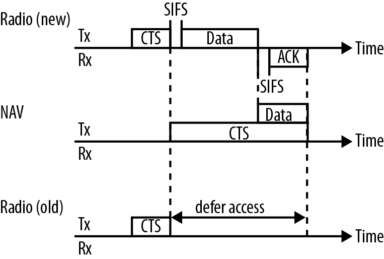
When using L-SIG duration, 802.11n devices will set the L-SIG duration to be the amount of time required to transmit the included HT frame, plus any amount of time required for the next frame in the sequence. During a multi-frame exchange, the MAC duration field may be set for the duration of the entire exchange, but the L-SIG duration will cover the next frame in the sequence. Figure 5-11 illustrates the difference between the two forms of duration setting, and it shows how the L-SIG duration is distinct from the MAC duration. On the radio link, the transmission is simple: a CTS-to-self, followed by a data frame that is acknowledged. At the MAC layer, the NAV is set according to the basic protection rules. In L-SIG protection, there is a second “duration” value calculated from the data rate and length transmitted in a frame’s PLCP header. Along the PHY line at the bottom of the figure, the shaded area along the PLCP line shows the extra length added to the legacy Signal field as computed by the PLCP. 802.11n’s mixed mode frame header is identical to that used by 802.11a/g, and therefore, it is possible to use the PLCP header to establish the time required for the transmission. Using the PLCP header requires somewhat less time on the medium because it does not require a whole separate frame and interframe space.

MAC-layer protection: CTS-to-self
Just as in 802.11g, an 802.11n device may transmit a control frame to lock up the medium for the duration of the entire HT exchange. Typically, the control frame will be a CTS-to-self to cause other devices in the area to defer access to the medium, though it is also possible to use a full RTS/CTS exchange. Control frames used to manage access to the medium are transmitted in a non-HT format so they can be understood by older stations. CTS-to-self protection may also be used to improve reliability.
MAC layer protection: transmission mode switch
A variation on the control frame-to-self mechanism described in the previous section is that the first frames in an exchange can be transmitted at non-HT rates, and set the MAC Duration field to lock up access to the medium. After the first two frames set at non-HT rates, it is then possible for the two devices in the exchange to switch to an HT mode and use whatever protocol options are desirable, including greenfield mode and the RIFS for the protected duration.
Protection Rules
The previous section described how protection works, but not when it is activated. Networks advertise the type of protection used through the HT Operation information element, described in Figure 5-3. 802.11n defines four protection modes, and each network selects one:
- No protection
Just as it sounds, in no protection mode there are no special transmission rules applied. This mode may only be set when all devices are 802.11n devices, and there are no non-802.11n devices detected. It is rare for an 802.11n network to be operating in no protection mode, especially in the 2.4 GHz band, due to the large number of existing 802.11 devices that were installed before 802.11n was standardized.
- Non-member protection
Non-member protection mode is used when a network must protect other devices from 802.11n transmissions. An example of this mode would be when I use an Apple AirPort Express 11n AP in a hotel room. On my network, I am using both an 802.11n laptop and an 802.11n AP, but the hotel’s network is not 802.11n. Therefore, non-member protection is used to prevent my 802.11n network from interfering with the hotel’s network. Non-member protection is only used when all devices attached to the network in protection mode are 802.11n devices.
- 20 MHz protection mode
This mode is not commonly used because it is activated only for a 20/40 MHz network. Most networks are set up for either 20 MHz channels or 40 MHz channels, and do not switch between the two dynamically.
- Non-HT mixed mode
This method, described in PHY-layer protection: L-SIG duration in HT-Mixed Mode, is the most common form of protection used because most networks require protection and many networks have a non-802.11n device attached. In this mode, transmissions are protected implicitly by the use of the mixed mode header, and no special procedures are required for 802.11a/g devices.
802.11n protection also interacts with the existing Use_Protection bit defined in 802.11g. When the 802.11g Use_Protection flag is set, any frame transmissions used for protection are sent at 802.11 direct sequence or 802.11b rates (1, 2, 5.5, or 11 Mbps).
Security
The basic security architecture first standardized in 802.11i did not require significant changes in 802.11n. There are three small changes to the security architecture. First, CCMP, the AES-based cryptographic protocol, was extended to protect the longer frames that appear in Figure 5-1. Second, the standard states that replay detection sets regular MAC payloads and aggregate MAC payloads on equal footing. Third, and most importantly, 802.11n specifies that TKIP is no longer allowed for use with 802.11n.
Whether to eliminate TKIP for use with 802.11n was a subject of debate within the 802.11 working group. TKIP was originally designed as a stopgap measure, and traded some amount of robustness in terms of security so that it could be retrofitted on to the then-existing 802.11b devices. TKIP’s design was not easily extended to new protocol features; for example, when QoS capabilities were added, TKIP’s design did not protect the contents of the QoS control field, which led to a small attack vector.[29] Further extending TKIP to protect fields added by 802.11n was too great a task.[30] As a result, there was never a codified technical standard for use of TKIP with 802.11n. In fact, the 802.11n standard went so far as to clearly and unambiguously state that the use of TKIP with 802.11n was strictly forbidden. Given that many 802.11n networks will be built after a hardware upgrade, it also made sense to the working group to use the 802.11n transition as a way to improve the overall security of wireless LANs.
Nevertheless, some early 802.11n products implemented an 802.11n-compatible version of TKIP. As a result, the Wi-Fi Alliance 802.11n certification program began performing negative tests that prevented the use of TKIP with 802.11n data rates. Many 802.11n products retain TKIP in a “legacy” mode, in which data rates are limited to 802.11a/b/g rates in order to continue the use of TKIP.
Warning
TKIP and WEP are not allowed with 802.11n, and are forbidden by Wi-Fi Alliance testing. 802.11a/b/g devices are still allowed to do TKIP. Many certified 11n devices implement TKIP and WEP, but forbid them from using 11n rates.
Mandatory MAC Features
To help readers keep track of features that are mandatory and optional, Table 5-4 classifies the protocol features into two categories. Generally speaking, the Wi-Fi Alliance test plan validates functionality that is mandatory in the specification, and has optional testing only for the most widely supported features.
| Feature | Mandatory/optional? | Comments |
| A-MPDU reception | Mandatory | Required by Wi-Fi Alliance test plan |
| A-MPDU transmission | Optional | Optionally tested by Wi-Fi Alliance test plan and displayed on interoperability certificate |
| A-MSDU reception | Mandatory | Required by Wi-Fi Alliance test plan |
| A-MSDU transmission | Optional | Not tested by Wi-Fi Alliance test plan |
| Block ACK | Mandatory | In addition to the basic requirements, 802.11n added support for the compressed block ACK |
| Protection | Mandatory | Basic protection mechanisms such as the CTS-to-self are required, but the L-SIG spoofing option is optional |
| RIFS receive | Mandatory | |
| Spatial Multiplexing Power Save | Mandatory | |
| No use of TKIP with HT rates | Mandatory | Validated by Wi-Fi Alliance test plan |
| Phased Coexistence | Optional | Not widely implemented, and not discussed in this book |
| Power Save Multi-Poll | Optional | Not widely implemented; see Chapter 6 |
[24] I am not aware of any detailed studies that compare various aggregation implementations. The effectiveness of an aggregation implementation will depend a great deal on the traffic mix on your network. If you expect heavy loads, it is worth looking at how aggregation will improve performance with your particular traffic mix.
[25] See Figures 4-4 and 4-5 in 802.11 Wireless Networks: The Definitive Guide for a discussion of the difference between the destination address and the receiver address.
[26] Although the aggregation is happening within the logical entity called “the MAC” in the standard, in implementation terms A-MSDU is typically carried out by the network driver. Aggregation therefore uses the host CPU and memory rather than the dedicated processing power on the radio card.
[27] Medium access is discussed in Chapters 3 and 4 of 802.11 Wireless Networks: The Definitive Guide.
[28] For more information on the protection mechanisms added in 802.11g, see Chapter 14 of 802.11 Wireless Networks: The Definitive Guide.
[29] The attack that was published was called Tews-Beck, after the two security researchers who discovered it. One of the better write-ups on the attack is Glenn Fleishman’s article for Ars Technica.
[30] TKIP is based on WEP, and requires the initialization of the RC4 cipher for every frame it protects. In A-MPDU aggregation, each subframe must be encrypted separately, and there is not enough time to re-initialize an RC4 cipher engine in the quick turnaround time between the processing of subframes.