Chapter 8. Designing and Installing an 802.11n Network
With planning out of the way, it’s time to get down to the details of network design. Once you are secure in the knowledge of what your network must support, you can run through straightforward project planning to build it. Begin with understanding what it means to extend the access layer of the network out using a wireless link, and then select an appropriate product. Physical installation comes relatively late in the process, followed by basic network monitoring to make sure that the network is meeting your requirements.
Network Architecture for 802.11n
Throughout the evolution of wireless LAN technology, there have been a number of approaches to add the wireless LAN access layer on to an existing wired backbone network. Most approaches share two fundamental attributes:
MAC-layer mobility (also called “layer 2” mobility after the OSI model). 802.11 works by “hiding” the motion of a device from the network backbone. Even though a wireless LAN-equipped device is moving in space, from the perspective of routers and switches, it is remaining on the same broadcast segment out at the edge of the network. Within a single broadcast segment, mobility is easy. A decade ago, providing continuous connectivity across a routed (layer 3) boundary was difficult, but every commercially-available product suitable for use in a large-scale environment has addressed the “subnet roaming” question. Wireless products provide this capability within the MAC layer—as an 802.11 device moves around, it continues to send frames to its default gateway, regardless of where it has attached to the network.[39]
802.1X security (also called “WPA2-Enterprise” after the Wi-Fi Alliance certification, or “layer 2 security” to contrast with IPsec or SSL VPNs). “Wireless security” has gone from being a laugh line in 2002 to something that is now taken for granted. Arguably, the typical wireless LAN with strong user authentication and encryption is now more secure than the wired backbone it connects to. In 2006, the Wi-Fi Alliance began requiring that all certified products implement version 2 of the Wi-Fi Protected Access specification (WPA2). Although there are many products that have not been certified, they often make use of components designed for use in certified products. WPA2 is stable, proven security, and is now widely used. WPA2-Enterprise offers network administrators the capability of designing network authentication around existing user databases, and extends the role information stored in those user databases out to the access layer. Typically, the “role” assigned to a user is enforced based on a combination of VLAN assignment at the edge, perhaps with additional IP filtering or QoS information.
Control plane location. In addition to protocol layering such as the familiar 7-layer ISO model, network technologies can be divided into planes. Each plane has its own protocol layers, of course, but the plane has a specialized purpose (Figure 8-1). Common planes are the data plane, management plane, and control plane:
- Data plane
Protocols in the data plane move bits from one location to another, and are concerned with moving frames from input interfaces to output interfaces. In an IP network, the main data plane protocols are TCP and IP, with applications such as HTTP riding on top of the network and transport layers.
- Management plane
The management plane provides protocols that allow network administrators to configure and monitor network elements. In an IP network, SNMP is a protocol in the management plane. A vendor’s configuration application would also reside in the management plane; wireless LANs may use CAPWAP as a transport protocol in the management plane. Without exception, large scale IP networks use centralized management, and thus, have a centralized management plane.
- Control plane
The control plane helps make the network operate smoothly by changing the behavior of the data plane. An IP network uses routing protocols for control, while switched networks use the spanning tree protocol.[40] The control plane of a wireless LAN is responsible for ensuring mobility between access points, coordinating radio channel selection, and authenticating users, among other tasks.

Wireless networks can be classified based on the location of the control plane, and much of the development across the history of wireless LANs is about refinements to the control plane. Consider the three basic architectures shown in Figure 8-2. When wireless LANs were first developed and network administrators were forced to deal with “stone age” products (roughly 1997-2003), building a wireless LAN was a significant undertaking. The simple explanation for the complexity of building a network is that adding the wireless access layer to the network meant that the number of network devices went through the roof. One network architect I worked with in the first half of the 2000s estimated that adding wireless access to the network had doubled the number of network elements he was responsible for. More formally, the network in Figure 8-2(a) consists of individual “autonomous” APs, and the management plane is distributed among all the APs. A few vendors selling autonomous access points did build centralized management tools, but most did not. More importantly, the control plane in a network of autonomous APs may not exist as a coherent whole, meaning that moving between access points was not guaranteed to work smoothly and there was little coordination between APs in making use of the radio environment.
The “iron age” of wireless LANs came with the emergence of wireless LAN controllers around 2003-4, and led to a design like Figure 8-2(b). The management plane was moved from the APs into controllers, and a centralized management application provided an overview of the entire wireless network. More importantly, the aptly named controllers brought the first coherent control plane functionality to the wireless LAN. Part of the reason for the development of controllers was that the processing horsepower needed for control plane functions was more affordable when it was provided in one location. In a typical controller-based deployment, the access points have limited functionality without the intelligence provided by the controller. Authenticating and authorizing users is handled by the controller, as are algorithms that provide RF management functions such as channel selection. Centralized management and control made it possible to build much larger networks, and most large scale networks that were built prior to the emergence of 802.11n were built using controllers. Early controllers also centralized the data plane as well by requiring that all traffic from APs be sent through the controller; this is often referred to as a network overlay because the wireless network was separate from the existing core network and layered on top of it. In effect, the controller took on the role of a distribution switch for users attached to APs and provided mobility by serving as an anchor for the logical point of attachment.
With the emergence of 802.11n, traffic volumes increased dramatically. 802.11n increased the speed of each individual device, of course, but the high capacity of 802.11n also made it possible to use more mobile devices. The increased load could no longer be put through a single choke point on the network, and led to network designs like Figure 8-2(c), in which APs are directly connected to the network and traffic flows out from the AP on to the network. This approach is sometimes referred to as distributed forwarding because the data plane function has moved from the controller out to the AP. Although this architecture looks superficially similar to autonomous APs, it is typically paired with centralized management. More importantly, the availability of increased processing power has made the typical AP significantly more powerful than it was in the iron age. With increased processing power, it is possible to move the control plane out of a centralized location and distribute it through the network. Distributed AP deployments have varying control-plane functionality based on the vendor; typical control-plane functions that may be available in a distributed access point include radio tuning, tunneling to provide mobility support to end-user devices, security functions, and evenly distributing the user load across APs.

Architecture Comparison
Building a “micro-network” of a AP or two is easy. With a small number of APs, it is acceptable to manage APs individually. Upgrading to 802.11n is also straightforward: take out your existing 802.11a/b/g APs and replace them with 802.11n APs. At such a small scale, almost anything will work. That is, unless your micro-network is actually one small piece of a larger network, in which case you should skip ahead a couple of sections and start reading. At some point, the overhead of managing individual devices will be too great, at which point you are building a small- or medium-size network. These networks have just as much to gain from 802.11n. Building a small network of five to ten APs is too small to use the “big iron” of controllers, but it is large enough to require centralized management.
Prior to the widespread use of 802.11n, large networks needed a centralized control plane to handle the loads imposed by large numbers of users, and the choice between autonomous APs and controller-based APs was a straightforward one that was almost always resolved in favor of the more advanced centralized control plane. 802.11n enabled a change in user attitudes towards connectivity that has driven the development of distributed control planes. As wireless LANs became viewed as stable, many new devices are being built without Ethernet—the MacBook Air was one of the first examples, and the number and variety of tablet devices is another. With users switching towards mobile battery-operated devices that they can use on the go, a significant portion of the network access layer has moved from traditional wired Ethernet to wireless networks. With the explosion of 802.11 devices now available, network architects have designed higher- and higher-capacity networks, stressing the centralized control plane. Early controller-based networks were able to use a single controller as the focal point for both the control and the data plane, but that assumption no longer holds.
Table 8-1 compares the three basic architectures. In reality, there is some overlap between these architectures when they are implemented in products. It is likely that a large-scale network at any speed, especially one supporting critical applications, will require some degree of decentralization, either by moving some of the data plane functions to the edge of the network, some of the control plane functions to the edge of the network, or both. All three architectures are capable of supporting any set of network requirements, but the cost and availability of the resulting network may vary.
| Attribute | Autonomous APs | Controller-based APs | Distributed APs |
| Location of data plane | Distributed, enabling high network performance | Centralized, potentially limiting performance to the forwarding capacity of a controller. Good mobility support because devices attach through the controller. | Distributed, enabling high network performance. Many products have features to assist with mobility. |
| Location of management plane | Depends on product; often distributed, imposing very high staff costs | Centralized, lowering operational expenses | Depends on product; often centralized, enabling lower operational expenses |
| Location of control plane | Distributed, if it exists. Non-existent control plane limits flexibility of security and radio management. | Centralized, with high functionality for radio management and user management. | Distributed. Functionality of control plane depends on vendor implementation. |
Management plane
If you are building a large-scale network, there is nothing to consider regarding the management plane. You need centralized management—otherwise, maintaining configuration across multiple devices will quickly break down. With early wireless LANs, there were some products that didn’t have centralized management, but those days are thankfully long behind us. Any 802.11n product designed for use in a network beyond home-size scales has central management, though there are of course large differences in functionality and cost. If you have a relatively small network, the software-as-a-service model may offer you the ability to use a full-featured management system.
Note
Centralized management is non-negotiable beyond just a few access points.
Data plane
This section has presented each of the three architectures with sharp lines between them. In actual products, the location of data forwarding is one of the places where products offer flexibility. Many controller-based APs can be configured to send data either through a centralized controller or directly from the AP to the network. Some common hybrid approaches are to offer a choice on a per-SSID basis so that guest traffic can be centrally forwarded, or that traffic from devices attached to the AP’s VLAN can be forwarded by the AP while traffic bound for VLANs attached to other APs must be send through the controller’s forwarding engine. Likewise, some distributed data planes offer roaming capabilities that can make any VLAN accessible throughout the network by tunneling between APs.
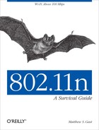
When a centralized data plane is used, 802.11n APs may also benefit from jumbo frame support and path MTU discovery. In the centralized forwarding model, illustrated by the top AP in Figure 8-3, data frames from client devices are transmitted from the AP to the controller through a tunnel that traverses the network backbone. For a transmitted frame to be sent to its network destination, it is received by the AP, passed to the controller through the tunnel, and then placed on the network by the controller.
For efficiency, client devices generally send maximum-length Ethernet frames of 1,500 bytes. Unless the path between the AP and controller can handle jumbo frames, it will have to fragment client traffic, resulting in a 1,500-byte frame that contains most of the client’s frame, followed by a second frame that has the remainder of the client’s data. There are four main ways to cope with the potential for fragmentation in a controller-based architecture:
- Jumbo frame support
If the path between the AP and controller supports jumbo frames, nothing happens. The AP takes the client’s data frame, puts a tunnel header on it, and sends the slightly larger tunneled frame across the network. There is an theoretical (and, in practice, imperceptible) penalty in speed because the tunneled frame is slightly larger, but the overhead is so minimal that I doubt any real-life network has measured the performance impact.
- IP stack fragmentation
IP itself can fragment frames. When the client data frame comes to the AP, it is given a tunnel header, and the resulting packet for transmission to the controller exceeds 1,500 bytes. As a result, the IP stack will fragment the packet into a maximum-size packet plus a fragment. When both the first packet and its trailing fragment arrive at the controller, they are reassembled into a single IP packet, the tunnel header is removed, and the client’s data frame is processed. Using IP-level fragmentation takes advantage of existing fragmentation code that is well-understood, but it does impose a cost on the controller in terms of packet buffer memory and processor load; the backbone must also forward two packets instead of just one. Depending on the network architecture, the tunnel may also break; most firewalls drop all IP fragments without further analysis.
- Controller tunnel (CAPWAP) fragmentation
As an alternative to using fragmentation and reassembly in the IP stack, the tunneling protocol between the AP and controller can implement its own fragmentation protocol. In fact, the Control and Provisioning of Wireless Access Points (CAPWAP) protocol, specified in RFC 5415, specifies its own fragmentation layer (see section 3.4). Fragmentation at the tunneling protocol improves firewall traversal because most firewalls do not perform detailed analysis of traffic beyond IP headers.
- TCP Maximum Segment Size control
The initial setup of a TCP connection includes a Maximum Segment Size (MSS). Some APs can rewrite the MSS value sent by clients so that the clients send frames that are small enough that the client frame plus the tunnel header is exactly the maximum size packet for the AP-to-backbone connection.
Additionally, there is one additional way to connect APs to the backbone network to avoid fragmentation concerns. Instead of using a tunneling protocol to reach a central point of attachment, some APs can connect directly to the network edge and forward traffic through the edge switch, as illustrated by the bottom AP. APs that support direct connection to the network do not require jumbo frame support.
Many commercial products on the market offer a combination of the approaches in Figure 8-3. Some controller-based APs can be configured to send data either through a centralized controller or directly from the AP to the network. Some common hybrid approaches are to offer a choice on a per-SSID basis so that guest traffic can be centrally forwarded, or that traffic from devices attached to the AP’s VLAN can be forwarded by the AP while traffic bound for VLANs attached to other APs must be send through the controller’s forwarding engine. Likewise, some distributed data planes offer roaming capabilities that can make any VLAN accessible throughout the network by tunneling between APs.
Note
With an 802.11n network of any size, it is likely you need to use both distributed data forwarding as well as the ability to forward wireless traffic across broadcast domain boundaries.
Control plane
The location of the control plane is the source of most architectural differentiation in available products. Centralized control plane technologies have been around for a long period of time, and are supported by mature, tested software, and can be combined with a distributed data plane for efficient use of the core network. Many centralized control planes are in the process of moving towards either a split control plane (where functions are shared between the controller and APs) or a more fully distributed control plane, but it is common that some features are not available when the controller is removed from the network. Distributed control planes can be cheaper, especially when designing for distributed networks with many remote sites.
The location of the control plane may have an effect on the overall reliability and resiliency of the network, which may be important depending on the applications in use and the structure of the network. For example, hospitals are increasingly turning to wireless LANs to support critical applications that distribute medical records, stream real-time data from patient care devices, fill prescriptions, and even make remote doctors available.[41]
To guard against downtime, it is necessary to build a redundant control plane in addition to a redundant data plane. Even with overlapping AP coverage, the network must enable client devices to quickly switch between APs. Simply handing off the wireless connection is easy; the difficulty in moving devices between APs is ensuring that QoS state, security keys, and firewall policy state also move between APs. Neither the distributed or centralized type of control plane is inherently more resilient; a distributed control plane protocol can be resilient by design, while a centralized control plane may require spare controllers.
Note
Carefully evaluate the trade-offs involved in a centralized versus a distributed control plane, and ensure that the control plane you select meets your needs for functionality, resiliency, and cost.
802.11n Hardware
After reviewing network requirements from the previous chapter and deciding on what constraints drive the logical architecture, it’s time to pick out access point hardware. Access points all perform the same basic function in that they shuttle frames between radio networks and Ethernet, but there can be tremendous differences in cost and functionality. Comparing access points on the basis of price alone is like saying that a Chevy Aveo and a Mazda Miata are the same because they are both cars that get you between two points.[42] To build a network of more than just a handful of access points, you probably want to look beyond the hardware available at electronics stores and at highly functional APs. Even a small network can benefit from corporate-grade APs—if you are running the network for a hedge fund, network performance is critical.
- Wi-Fi Alliance certification
A basic requirement is demonstrated interoperability with the Wi-Fi Alliance’s test suite. Certification is not an absolute guarantee of interoperability, but it is an obvious first step. To check on the certification status of a product, visit the Wi-Fi Alliance web site and click on the “Wi-Fi CERTIFIED Products” button on the left-hand side of the page. How to decipher the full certification information is discussed in the next section, Technology “Waves.”
- High performance
At the relatively low speeds of 802.11a/b/g, the demand for CPU power to run at “air rate” was relatively low. As speeds increase to the current state-of-the-art 450 Mbps, significantly more processing power is required to forward data, and the effects of tuning the software for speed will be more pronounced. A 5% increase in data rate at 802.11b rates is likely only half a megabit, but a 5% increase at 3-stream 802.11n speeds is in excess of 20 Mbps. Vendors of corporate-grade hardware invest much more heavily in software tuning because their products are sold where every bit per second matters.
- Hardware quality and robustness
Corporate-grade devices are designed to be used for many years before replacement, and therefore, are often designed with future expandability in mind. Components are selected based with a view towards quality and long life instead of primarily based on cost. Sophisticated antennas or other radio front-end components may be used to improve the quality of the network, either in terms of throughput or coverage. Radios will be enabled on all available channels even though the cost of regulatory compliance with DFS channels can be substantial, and software supports automatic configuration of radio channel selection.
- Software functionality, upgradability, and quality
Generally speaking, more expensive devices have significantly more functionality, with advanced features in several areas. Vendors regularly plan for the release of new features, and it is common for new features to be provided midway through a product’s life cycle. Additionally, extensive QA testing is used to ensure that corporate-grade devices can be run for months at a time under heavy loads.
- Antenna options
Internal antennas allow an AP to be self-contained, and to blend smoothly into the aesthetic environment. External antennas typically have higher gain, which improves range. In a deployment based on area coverage instead of density, or a deployment in a challenging radio environment, selecting the right external antenna can be the difference between a poor-quality network and a successful one. External antennas are also frequently used for outdoor deployments. Picking the right external antenna is still something of an art, and the antenna must be matched to the performance characteristics of the AP. A high-gain antenna will dramatically increase the transmit range of an AP, but if the AP has low receive sensitivity, the high-gain antenna will cause more problems than it solves.
- Power options
Consumer-grade devices are typically powered with a “wall wart” transformer and must be installed close to existing electrical outlets, while corporate-grade devices can draw power from the device at the other end of the Ethernet cable. Power over Ethernet enables placement of devices in out-of-the way locations, and can be used to provide power even on very high ceilings.
- Security
Security is not just about providing solid encryption, though that is the obvious starting point. Corporate-grade products offer flexible authentication through RADIUS and directory interfaces, per-user VLAN mapping, traffic filtering and queuing, and built-in captive web portals for web-based authentication.
- Quality of service
At the most basic level, quality of service support is compliance with the Wi-Fi Multi-media (WMM) certification requirements, which divides traffic on the air into four classes of differing priority. More complex queuing systems can be used to improve service quality for voice devices, or to ensure that airtime is balanced fairly between network users.
- Manageability
If you are reading this book, you need centralized management. Evaluate management tools for a wireless network in the way that you evaluate management tools for a wired network. Ensure that the management software provides something beyond simple configuration management and can report on the overall state of the network.
Technology “Waves”
802.11n is a complex standard with interdependent pieces. Previous PHYs were able to come to market all in once piece, so that 802.11g did not exist, and then it did, fully formed. The complexity of 802.11n means that it has come to market in distinct “waves” or “phases.” Part of the reason for phases is that the difficulty in standardization is determining what the frame format should be, and what is eventually possible to build into hardware. However, the incremental work in adding 4-stream transmission to 802.11n is very small compared to the hardware engineering needed to put four radio chains in close proximity.
One way of thinking about the market is to think of it in technology waves, where a wave is a set of products that hit the market at about the same time. When building wireless LAN products, the most important component is the radio chipset, a set of silicon chips that implement the components shown in Figure 3-7. Typically, the amplifiers are put on a radio front-end card, which allows them to be customized to a particular application. Long-distance transmission or high rate-over-range can be achieved by using higher-quality radio front-ends. The radio chip itself will have a PHY section that demodulates data, possibly from several data streams, and corrects any errors by using the error-correcting code. The resulting bit stream is passed to the MAC where security is applied, any frame deaggregation is done, and so on. APs are built around radio chips, so the technology waves in APs are driven by new radio chipsets.
In 2006, the 802.11n market was tiny, and the draft 802.11n standard was only in its first draft.[43] Several areas of the standard had different interpretations, and radio chipsets for 802.11n were maturing along with the draft standard itself. Many of the earliest chipsets only supported operation in 2.4 GHz, and the only way to guarantee interoperability was to buy products that used the same chipset vendor. In retrospect, I labeled the 2006 time frame as the zeroth wave because there wasn’t really a large market.
The first wave came a year later, with the second draft of 802.11n. After the 12,000 comments received against the first draft, the second draft was much expanded and refined. Due to the perception of non-interoperability, the Wi-Fi Alliance began certifying products against the developing standard, an action which helped focus the standards developers on working out the major contributors to interoperability. The draft 2.0 certification program cemented the major components of the developing standard in place, and created a market where interoperability was tested and became a major focus of product vendors. The first wave was when 5 GHz products came to market, as well as when 802.11n enterprise devices emerged, most of which used a 3x3 MIMO design that supported two spatial streams. Power consumption of these APs was quite high, and often exceeded the 802.3af power budget.
The second wave of products was driven by the ratification of the 802.11n standard in 2009. Customer feedback on the first wave of enterprise devices was that full functionality was required on the 802.3af power budget, and the industry responded. Second-generation 802.11n hardware from chipmakers were 2×2 MIMO designs supporting two spatial streams. Removing the third radio chain and using better chip manufacturing techniques meant that the second-generation of 802.11n enterprise devices operated at similar speeds for the end users, but with much lower power consumption.
The third wave of products in the enterprise came in 2011, as 3×3 MIMO designs supporting three spatial streams came to market. At the time this book was written, high-end APs were all three-stream designs. It is likely, though not definite, that most chip designers will focus their four-stream efforts on 802.11ac, the forthcoming gigabit standard.
Wi-Fi Alliance Certification
The Wi-Fi Alliance is an industry association of companies that are driving wireless LAN technology. The Alliance is best known for the Wi-Fi CERTIFIED interoperability testing program that began in 2000. Prior to 802.11n, the underlying PHYs were simple enough that there was a single set of core capabilities and very few optional features. The statement that “this device supports 802.11a” meant the same thing for any 802.11a device. With 802.11n, however, the underlying technology is much more complex. 802.11n devices certified for interoperability by the Wi-Fi Alliance are given the designation Wi-Fi CERTIFIED n, and are required to meet a minimum set of 802.11n technology components.
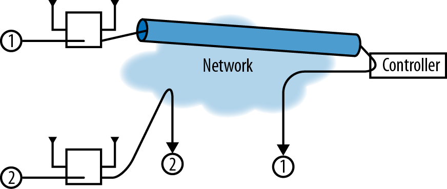
Once certification is complete and a product is awarded certification, it can be looked up at the Wi-Fi Alliance certified product listing. Each product is also given an interoperability certificate that details the individual product features that have been certified. Figure 8-4 shows a sample interoperability certificate, in this case, for an Aerohive HiveAP 330. In the upper-left hand corner of the interoperability certificate, the Wi-Fi CERTIFIED logo shows the basic interoperability certification (in this case, 802.11a/b/g/n); these logos often appear on product literature and packaging. Below the certification logo, there is a box noting the number of spatial streams supported by the device (in this case, three). As a point of contrast, Figure 8-5 shows a certificate for a client device (in this case, for a Dell card used as a reference design). This card has support for the greenfield preamble and wide channels in the 2.4 GHz band, both of which are displayed in the left-hand column.

Mandatory tests
Every device submitted for 802.11n certification must pass a series of basic tests that are expected to be supported by every 802.11n device. These features include:
- Minimum number of spatial streams
APs must support at least two streams before being allowed to use the 802.11n logo. No such rule applies to client devices. The number of declared spatial streams, up to 3, is tested and placed on the interoperability certificate. The HiveAP 330 certificate indicates that it can support 3-stream operation for both transmission and reception in both radio bands.
- A-MPDU reception
Any Wi-Fi CERTIFIED n device must be able to receive A-MPDU frames. A-MPDU support is typically provided within the 802.11n chip itself, so this support for option is widespread throughout the history of 802.11n. Devices under test are allowed to self-describe the A-MPDU size supported, so it is impossible to determine whether the A-MPDU implementation supports a high density of back-to-back MPDUs or something less capable.
- A-MSDU reception
In addition to the A-MPDU aggregation, devices must support A-MSDU reception as well before being certified.
- Overlapping BSS (both bands)
The overlapping BSS test ensures that an 802.11n network whose coverage are overlaps with an 802.11a/b/g network does not cause interference to the legacy network.
- Reduced Interframe Space (RIFS) support
Tests validate the use of the RIFS for efficiency. At the start of the Wi-Fi CERTIFIED n program, this capability was not required, but it has been required since the middle of 2008.
- Security: TKIP & WEP negative tests
802.11n devices may not use TKIP or WEP to protect frames sent at 802.11n data rates. The certification program includes “negative tests,” which are tests to ensure that WEP and TKIP cannot be used with 802.11n data rates. Many products implement data rate limits when WEP or TKIP are configured, so that if an 802.11n network is configured for TKIP, its components will avoid using data rates higher than 54 Mbps.
Optional tests
In addition to the mandatory tests described in the previous section, the certification program includes a number of optional capabilities, each of which is called out on the interoperability certificate.
- 40 MHz operation in 5 GHz
The use of wide channels in 5 GHz enables greater throughput. This option is commonly supported by enterprise devices intended for large-scale high-throughput environments. At the time this book was written, slightly over three-quarters of enterprise networking devices support this option.
- 40 MHz operation in 2.4 GHz (including coexistence)
As with the previous option, this item indicates support for 40 MHz channels in the 2.4 GHz band, with a catch. It is not possible to implement 40 MHz channels in the 2.4 GHz band and pass the test unless the 20/40 MHz coexistence features described in Chapter 6 are also implemented. Because spectrum is scarce in the 2.4 GHz band and 40 MHz channels upset the existing 3-channel plan, this option is not widely certified. Only about a quarter of Wi-Fi CERTIFIED n devices implement this feature.
- Short Guard Interval
Support for the short guard interval is widespread. It increases throughput by about 10%, and is widely supported by the chipsets that power wireless LAN devices. Almost three-quarters of all Wi-Fi CERTIFIED n devices support the short guard interval, with an even higher fraction of enterprise networking devices including support.
- Space-Time Block Coding (STBC)
STBC improves the ability of a signal to travel farther because it uses all of the MIMO signal processing gains to increase range. STBC is not widely implemented, and is certified in less than a fifth of Wi-Fi CERTIFIED n devices.
- Transmission of A-MPDUs
Tests that the device supports sending A-MPDUs. This is the only aggregation test; the certification testing does not validate A-MSDU behavior. About half of certified devices support this feature.
- Greenfield mode
Greenfield mode improves efficiency at the cost of easy interoperability with 802.11a and 802.11g networks. Greenfield mode is supported in about a quarter of all certified devices, but it is extremely rare in enterprise-class APs.
- HT Duplicate Mode (MCS 32)
HT Duplicate mode improves error rate performance. It consists of one mode of operation at 6 Mbps that sends the identical data stream on both halves of a 40 MHz channel. It is implemented by less than a fifth of certified devices, and not discussed in detail in this book.
Access points that implement 802.11n with a single spatial stream are not allowed to claim that they are certified for 802.11n. As a compromise, however, APs that pass any test in this section can be certified and use the logo that indicates “with some n features.” For example, a device that implemented single-stream 802.11n and supported 40 MHz channels could be labeled as “Wi-Fi CERTIFIED 802.11a/b/g with some n features.”
Coverage and Capacity Planning
When 802.11 first emerged, radio planning was a complex undertaking because there was almost a master craftsman’s touch to walking a building, estimating coverage areas, and assigning non-overlapping channels to maximize throughput. Those days are long gone. Any wireless LAN system that works at the scale of more than a few APs has an automatic radio tuning system built in. APs continuously assess channel quality on a basket of factors, and choose the “best” channel according to an algorithm that typically uses the number of overlapping APs on each channel, the signal strength of those overlapping APs, and a channel loading figure.
With channel selection handed over to the wireless LAN itself, network administrators can focus on the higher-level questions of ensuring that the network is built to meet its desired goals. Rather than delving into the minutiae of wringing marginal performance gains out of a slightly improved channel map, administrators can spend time on the bigger questions to build the maximum network capacity within a given budget. Generally speaking, the service side of wireless LAN installation is about where to put APs and the assignment of channels to those APs; the cost side is not just about the equipment, but also includes the cost of installation.
Wireless LAN network capacity comes from huge tracts of clean spectrum. 802.11n does not define usage in a new band of spectrum. Rather, it coexists in the 2.4 GHz band with 802.11b/g and in the 5 GHz band with 802.11a. As wireless networks have become accepted (or even loved), the constraints on the 2.4 GHz band and its three channels have become more pronounced. Except for all but the most basic networks, a wireless LAN needs the extra capacity available in the 5 GHz band. The 5 GHz band provides more channels, plus the capability to build smaller coverage cells for better frequency reuse.
Note
Unlike previous physical layers, 802.11n is capable of using both the 2.4 GHz (“802.11ng”) and 5 GHz (“802.11na”) radio bands. For high capacity, you will need to use both of them at the same time.
The number of APs needed to build a network is determined by the desired performance of the network as a system. Pick a device as the worst-case performance target; the target device will often be a single-stream device such as a phone or tablet. Estimate the number of devices on the network and the required system-wide performance to get a “capacity” target AP count. Next, estimate the coverage area of an AP based on the required signal strength to provide adequate coverage. Many single-stream devices will require that the network be designed around a signal strength of -67 dBm. Using a planning tool, get a “coverage” target AP count. Obviously, pick the larger of the two numbers. In many environments, the AP layout will be a blend between coverage and capacity, with high-density areas getting a closely packed AP deployment while areas with lower user densities will use the more sparse coverage plan. As you set up capacity plans for a network, allow for sufficient capacity so that the network will meet user demands into the future. A variety of tools exist that can assist with network planning, and a few vendors offer free estimates of either the AP count or mounting locations.
AP Mounting Locations
If your 802.11n network is an upgrade from an existing 802.11a/b/g network, a good first step in getting maximum performance for a given cost is to reuse existing mounting locations. Cabling is often one of the major costs of building a wireless LAN, and reusing existing cabling is a good first step, especially if the cabling is in place to many of the locations where you would want to put wireless LAN coverage.
802.11n APs might show a small increase in speed by moving to a new mounting location, but the cost involved in resurveying and recabling new locations is almost always prohibitive. From a cost efficiency standpoint, it is cheapest to install 802.11n APs in the same locations as the existing 802.11a/b/g APs, and then add extra capacity where it is required. Typically, 802.11n offers the highest benefits in high-density/high-capacity locations such as auditoriums, conference rooms, and other areas where large numbers of users tend to gather. As demands on the network grow, additional capacity can be added as network usage increases.
When building a new 802.11n network, especially for coverage, it is best to design the network around the needs of 5 GHz coverage. Because radio range at 5 GHz is somewhat shorter, and the 5 GHz band bears the brunt of building a high-capacity network, it is best to lay out a new network with mounting locations selected to obtain desired 5 GHz coverage. Only once that is complete, enable radios on the 2.4 GHz band. Due to the longer reach at the lower-frequency band, only a subset of APs will need to have their 2.4 GHz radios active.
Channel Types and Layout
The easiest component of channel layout is the channel assignments. Just let your network pick channels itself. With rare exceptions, automatic channel selection algorithms converge on a good enough channel plan that the gain in speed from picking channels manually is quite low and not worth the time.[44] The important inputs to channel selection algorithms are the available channels and the capacity of each channel. 802.11n offers two channel widths: a backwards-compatible 20 MHz channel that is identical to 802.11a/g, and a new 40 MHz wide channel that offers slightly more than double the speed.
Warning
Do not use 40 MHz channels in the 2.4 GHz band. With only 83 MHz of spectrum, you have space for just two, and that’s only if you ignore the overlap problems. Just don’t do it.
Practically speaking, an extensive deployment of 40 MHz channels will need support for the worldwide harmonized radio band (channels 100 to 144 in Figure 3-3). Using these channels requires that the AP support Dynamic Frequency Selection (DFS). DFS capabilities are required by radio regulators in each individual country, and support is tested as part of the government certification process required to sell radio devices. Without DFS, wireless networks in Europe are restricted to four indoor 40 MHz channels and wireless networks in the U.S. are limited to six. A key enabling technology for DFS operation is the IEEE 802.11h amendment, which is tested by the Wi-Fi Alliance and appears on the interoperability certificate as shown in Figure 8-4.[45]
DFS support enables outdoor operations in Europe, as well as adding five additional 40 MHz channels.
Note
40 MHz channels reduce the number of allowed channels by half. In order to have a reasonable channel layout, you need 4 to 6 available channels, which means that DFS certification and operation are a practical requirement.
Although DFS operation improves the number of channels, it is not perfect. Spectrum is the lifeblood of wireless LANs, and many channels are available on the condition that wireless LAN operation is secondary to primary uses of the band. Operation on channels where another use takes priority, such as weather radar on channels 100 to 144, requires that APs monitor for higher-priority transmissions and switch channels to avoid causing interference. Getting DFS right is tricky because an AP must cede the channel to a higher-priority use, but if it is too sensitive the resulting channel changes will result in unwanted network disruption. The only remedy for a wireless network administrator is to carefully assess whether channels that require DFS are needed to meet the goals of the network and carefully monitor the network in operation to ensure that any channel changes are the result of actual interference and not merely false positives.
AP Transmit Power Setting
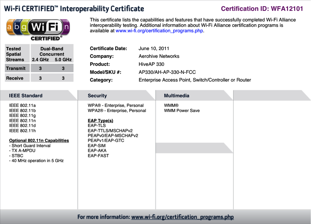
In addition to dynamic channel selection, many APs have the ability to automatically adjust transmit power through a function called Transmit Power Control (TPC). Transmit power adjustments are often described as a way to fill in coverage holes or otherwise help a network to “self-heal” in response to changes in the radio environment. TPC, however, can easily create asymmetric links, as shown in Figure 8-6. In Figure 8-6(a), the client device power is set much higher than the AP transmit power. Although the AP network has optimized itself for high coverage density with relatively low transmission power, a client device set for much higher transmission power may cause the carrier sense in a large surrounding area to read busy. Figure 8-6(b) shows the opposite problem, in which the AP transmit power is set very high and a low-power client is no longer able to reach the AP.
The key for network administrators in configuring TPC is to guard against both types of link asymmetry. Begin by determining the maximum transmit power of mobile devices, and capping the transmission power of each AP at the level of the typical client. Laptops typically transmit at a maximum power of 100 mW (20 dBm), but may be set lower to conserve battery power. Phones are often capable of the same power level, but higher transmit power does decrease battery life. A good compromise is to set the network for a maximum power of 30-50 mW (roughly 15-19 dBm).
Network Management
When problems arise after installing the network, administrators turn to analysis tools to diagnose the problem, find the root cause, and determine what configuration steps can be taken to eliminating the problem. Wireless networks are by no means trouble-free, but the underlying technology is now fairly mature. Network management applications play a critical role in network operations by automating the analysis and troubleshooting of problems. Good network management tools can help you check assumptions on the client device and traffic mix, as well as react to change in the usage of the network over time.
Network Analysis
In the early days of wireless LANs, just getting a packet capture could be a challenge. Thankfully, those days are behind us, and many software products exist to easily obtain a packet trace. For quick analysis, I use Wireshark because it is a cross-platform tool that is equally available on MacOS, Linux, and Windows, and my long history with tcpdump has resulted in the ability to write filter rules using the familiar Berkeley Packet Filter (BPF) syntax. Installation is straightforward, with ready-to-run code available easily.
Note
Wireshark requires system-level privileges to read the packet capture. On MacOS and Linux, make sure that the BPF devices are readable by the user running wireshark.
When doing frame analysis, your analyzer will read frames from the wireless interface and display their contents. Critically, the frame is only available if it is received by your analyzer. With Ethernet, the analyzer can be plugged in, and barring extremely unusual problems or bugs in port mirroring code, will receive frames without issue. On a wireless network, the analyzer only receives what it can decode. To troubleshoot client problems, it is often necessary to physically take the analyzer to the problematic location and set it down next to the device. Ideally, your analyzer will use the same chipset as the client device so that it has similar performance characteristics, though that will not be necessary in most cases.
Some APs include a remote capture tool, which has the advantage of providing the stream of frames as received by the AP. Remote capture from the AP can be used to diagnose problems by looking at the data stream from the AP’s vantage point, perhaps while cross-referencing with an analyzer on the client side. For example, if a connectivity problem occurs, comparing captures from the AP and an analyzer near the client device may help you determine if frames are being lost in the air.
Wireshark has several capture modes. For wireless LAN usage, you will want to capture in monitor mode, which reports all received frames up the software stack. Monitor mode is required to capture 802.11 header information as well as radio information such as the data rate and Received Signal Strength Indication (RSSI).
Network Tuning
The 802.11 MAC manages airtime, which means that performance tuning in 802.11n uses similar techniques to previous PHYs: reduce airtime contention when you can, and pack as many bits into each microsecond when that fails. Just as in 802.11a/b/g, reducing the coverage area of each AP works to increase the frequency reuse and provides independent channels. Just as in 802.11a/b/g, the spectrum in the 5 GHz channel is “cleaner,” with less interference, as well as the raw capacity from all the additional channels (see Channel Types and Layout). The past few years have seen greater appreciation of the role of 5 GHz channels in improving throughput. Physics plays a role here: 5 GHz radio waves travel a smaller distance, enabling better frequency re-use.
Note
Although 802.11n changed many rules of the game, it didn’t change them all. If you are building a high-capacity network, the 5 GHz band is your friend. Use it.
Many manufacturers select default settings that are generally good for data networking, and will deliver acceptable performance for web-based applications and email. In fact, for 802.11n APs, many APs include a feature that gives priority to high speed 802.11n frames because they move data much more quickly than the older 802.11a/b/g frames. When transmitting a 1500-byte Ethernet frame, 802.11n needs less than a third of the time to move the frame at 300 Mbps than 802.11a/g does at 54 Mbps. When you factor in aggregate frames, the time savings are even more pronounced. Preferential treatment for fast 802.11n frames has the apparent effect of speeding up the network for 802.11n users with only minimal impact to users of older devices.
Tuning for voice
Unlike a data-oriented network, some special configuration may be helpful for networks that support extensive amounts of voice traffic. Voice traffic is demanding because it cannot be buffered, so many of the efficiency enhancements in 802.11n are not used by voice handsets. The core of voice tuning is reducing latency for as much traffic as possible.
- QoS configuration: enable Wi-Fi Multi-Media (WMM) and priority queuing
WMM is a quality-of-service specification that can dramatically improve the quality of voice at the receiver.[46] Not all vendors turn on WMM by default. The single most important configuration change you can make to support higher-quality voice calls is to ensure that WMM is enabled. Some vendors also have an option for strict priority scheduling, which delivers frames in order to the receiver.
- Increase data rate used for Beacon frame transmission
Voice handsets are often very aggressive in roaming between APs, so tuning efforts will focus on decreasing the effective coverage area of APs and reducing large areas of coverage overlap. One of the most effective ways of limiting the effective range of an AP is to make its Beacon transmissions travel a shorter distance. While it is not possible to design a radio wave that stops at a certain distance, increasing the data rate of Beacon frames can be used to limit the effective range of the network. Typically, the Beacon rate will be set at a minimum of 24 Mbps, and sometimes even higher. (802.11a/g rates should be used because many voice handsets do not use 802.11n.)
- Limit use of lower data rates
In combination with using high-data rate Beacon transmission, turn off usage of the lower data rates. Many APs have the ability to disable low data rates, which assists clients in making decisions to move to new APs, and the use of high data rates decreases the overall airtime usage and average latency. Limiting low-speed data rates also helps voice networks function better by reducing the amount of airtime required by non-voice clients, leaving a larger share of airtime available for voice devices.
- Shorten DTIM interval
Many voice products use multicast frames for control features or for push-to-talk (PTT) features. Multicast frames are held for transmission until the Delivery TIM (DTIM).[47] Many APs will ship with a DTIM of 3, so multicast transmissions are delivered after every third Beacon. Setting the DTIM to 1 makes multicast delivery more frequent, at the cost of some battery life on handsets that need to power on after every Beacon to receive multicasts.
- Reduce retry counters
Voice is highly sensitive to latency. 802.11 will automatically retry failed transmissions, but retransmissions take additional time. In voice transmission, frames should arrive on time or not at all. Using network capacity to retransmit frames after the target delivery time does not improve call quality, but it can delay other voice frames in the transmit queue. Somewhat counterintuitively, reducing the frame retry count can improve overall latency, and therefore voice quality.
Tuning for multicast
Multicast applications are often similar to voice applications in terms of the demands placed on the network. Multicast traffic streams are often video, and may not be easily buffered. Furthermore, multicast traffic has a lower effective quality of service than unicast traffic on a wireless LAN because multicast frames are not positively acknowledged. In a stream of unicast frames, each frame will be acknowledged and retransmitted if necessary. Multicast transmission has no such reliability mechanism within 802.11, so a stream of multicast frames may not be received.
- Shorten DTIM interval
Just as with voice, many multicast applications depend on promptly receiving data. Setting the DTIM interval as low as possible improves the latency of multicast delivery.
- Increase the data rate for multicast frames
By default, many products will select a low data rate, often 2 Mbps, for multicast transmissions in an effort to be backward compatible. While this is a laudable goal, and the choice of 2 Mbps was reasonable during the 802.11b-to-802.11g transition in 2004, low data rates for multicast no longer serve that goal. Unless there are critical applications running on 2 Mbps devices, or there is a large number of such old devices on the network without any upgrade path, increase the multicast data rate to reduce airtime contention. Many APs can automatically set the multicast data rate to the minimum data rate used for unicast frames to associated clients, or even the minimum unicast rate for clients in the multicast group.
- Enable multicast-to-unicast conversion
Some APs implement a feature that converts a single multicast frame into a series of unicast frames. Multicast frames must be transmitted at a rate that can be decoded by all receivers, and is therefore often relatively slow. Unicast frames can be transmitted much faster if the receivers are close to the AP. A series of positively acknowledged unicast frames may take approximately the same amount of airtime, but have significantly greater reliability.
Implementation Checklist
When designing and building a network, use the following checklist:
- Choose an architecture
The easy choice in architecture is that the management plane must be centralized. In most cases, a hybrid data plane that blends aspects of both a distributed data plane and centralized forwarding will be the right choice. Carefully evaluate the trade-offs for the location of the management plane based on application requirements and cost.
- Hardware selection
Select hardware that meets requirements for performance and functionality, and is certified by the Wi-Fi Alliance.
- Coverage planning
Lay out a network for 5 GHz coverage, and turn on 2.4 GHz radios as needed to provide coverage. Consider turning on 40 MHz channels if high performance is needed.
- Tune for applications
Adjust the Beacon interval, DTIM, and data rates to suit the applications in use on the network.
[39] The alternative to MAC-layer mobility is to embed the mobility function within the network layer (layer 3 of the OSI model) with a protocol such as Mobile IP. Mobile IP was not widely adopted, in large part because of the extensive modification to the TCP/IP stack required on either the end-user devices or within the elements at the network edge.
[40] In IP networks, many protocols used for network control use the same transport protocols as the data plane. For example, routing protocols communicate using IP, but also those routing protocols also influence how IP datagrams are routed. In the telephone network, the control messages to set up and tear down telephone calls use a protocol named Signaling System 7 (SS7) and travel over a completely separate network from the telephone calls themselves.
[41] Broadly speaking, the ability to involve remote medical professionals is called “telemedicine,” and is enabled by videoconferencing plus a variety of healthcare information technology, supported by a robust network infrastructure. As you might expect, it is far too broad a topic to be discussed at any length in this book—but the supporting technology for that “last hop” to the handheld device is almost certainly going to be 802.11.
[42] This is funniest take on the Chevrolet Aveo that I have ever read: http://www.ginandtacos.com/2009/12/18/npf-ed-drives-tiny-car-hilarity-ensues/.
[43] The 802.11 timeline site is a fabulous resource for the progression of standards through the drafting process. 802.11n was being feverishly assembled in early 2006. The final votes to create draft 1.0 occurred at the March 2006 meeting in Denver, and the draft was balloted in April. The significantly improved draft 2.0 was not balloted until March 2007.
[44] Most of the exceptions involve the presence of persistent non-802.11 interference that dramatically reduces the capacity of a channel. However, this can be detected by its effects on throughput of attached devices, a combination of high signal strength with low data rates, or by spectrum analysis capabilities that are built into the AP itself.
[45] If you need lots of wide channels, check on the channels supported by your AP. At one point, the FCC suspended DFS certification testing for quite some time, leaving many products technically capable of supporting the DFS band unable to do so for legal reasons.
[46] In 2006, I experimented with an early WMM implementation on the Interop show floor to show the dramatic quality improvements with WMM.
[47] For more information on the operation of the DTIM, see Chapter 8 in 802.11 Wireless Networks: The Definitive Guide.