Chapter 3. Channels, Framing, and Coding
I like big channels, I cannot lie…
This chapter moves from the rarefied theoretical discussion of how MIMO works into the details of how the 802.11n PHY interfaces with the physical medium and delves into the details of the techniques that are used to increase speeds.
Channel Structure and Layout
The structure of a channel in 802.11n is basically the same as 802.11a/g. Both are based on OFDM, and therefore, both divide up the radio channel into a number of subcarriers that are packed closely together and precisely enough that they are orthogonal to each other. 802.11n provides several minor improvements to the structure of the channel. Like 802.11a/g, it uses OFDM and re-uses the same modulations and numbering scheme.[12]
Channel Structure
802.11n offers two features to increase the utilization of the radio spectrum. 802.11n retains the common 20 MHz channel width used by prior 802.11 standards. Within the 20 MHz channel, however, 802.11n improves spectral efficiency by adding subcarriers that were unused in 802.11a/g, as shown in Figure 3-1. Even though 802.11n adds four data subcarriers, increasing throughput by about 8%, it does not need to add any pilot subcarriers. Pilot subcarriers are used to provide channel measurement and calibration, and are a form of overhead. Just as MIMO increases the efficiency of a data transmission, it increases the efficiency of the pilot carrier operation. In a MIMO system, each subcarrier will be received through each of the received radio chains, and thus, will provide more information on the state of the channel as in a SISO system.

The second change made by 802.11n is that it supports operation in wider 40 MHz channels. Although the standard describes several methods of operating a 40 MHz channel, by far the most common one is that two adjacent 20 MHz channels are treated as one channel and treated as a single 40 MHz contiguous block.
Even though the center frequency of a 40 MHz channel moves upward, the “name” of the channel does not change. For example, a 20 MHz channel operating on channel 60 can be used next to a 20 MHz channel operating on channel 64. However, an AP advertising a 40 MHz bandwidth at channel 60 occupies the spectrum for both channel number 60 and channel number 64. Figure 3-2 illustrates the differing channel widths.

802.11n’s 40 MHz channels do more than double the throughput when compared to the traditional narrow channels because the 40 MHz channel format decreases overhead as a fraction of the channel. Pilot carriers are an “overhead” expense required in OFDM, and do not transmit any data from higher protocol layers. 802.11n doubled the channel width from 20 MHz to 40 MHz, but only increased the number of pilot carriers by half, as described in Table 3-1. By using the increased effectiveness of pilot carriers in a MIMO system, the spectral efficiency increases by 4%.
Regulatory Rules and Operating Channels
As with anything related to radio transmission in 802.11, regulatory considerations are an important part of how much data a network can support. Although the 802.11 specifications define a large number of channels, especially in the various 5 GHz bands, they are only available for use if allowed by the regulatory authority in the country where an AP is installed. 802.11n operates in both the 2.4 GHz band used by 802.11b/g as well as the 5 GHz band used by 802.11a.[13] In both cases, 802.11n reuses the channel numbering that was established by previous standards. Figure 3-3 illustrates the latest available information on regulations in the 5 GHz band. Channels are identified by the IEEE channel number across the top of the diagram, and blocks indicate whether a 20 MHz or 40 MHz channel is available for use. The broad band in the middle of the figure, 5.470–5.725 GHz, has been the subject of intense interest. It is generally available throughout the world for use, and represents a substantial increase in available spectrum for building wireless LANs.

One of the reasons why the 5.470 GHz spectrum became available is that its previous use generally allowed for a secondary user of the band. It is widely used for weather radar. Wireless LAN use of the band is secondary, meaning that if radar signals are detected the wireless LAN must be automatically shut down. However, such a high frequency generally does not impinge on operation of indoor wireless LANs. This band is sometimes referred to as the Dynamic Frequency Selection (or DFS) band after the required procedures to detect radar and avoid interfering with the allocated use of the band. Certification to operate within the DFS band is generally granted by the radio regulator in a country after testing to ensure compliance with the relevant rules.[14] Use of 40 MHz channels substantially increases the demand on spectrum resources, and the ability to use 40 MHz channels will typically depend on whether the network components can support channels on which DFS operations are required.
Transmission: Modulation and Guard Interval
When a frame is transmitted, there are two separate parameters that 802.11n stations must agree on. First, the transmitter must select the modulation rate and coding that describes how data will be turned into radio waves. Second, the transmitter must select a guard interval; 802.11n optionally allows a shorter guard interval than previous standards.
Modulation and Coding Set (MCS)
In 802.11n, the Modulation and Coding Set (MCS) number is a value that describes the number of spatial streams, modulation (BPSK, QPSK, 16-QAM, or 64-QAM), and error-correcting code used for a transmission. 802.11n supports both equal modulation, in which all spatial streams are transmitted in the same manner, and unequal modulation, in which the spatial streams may be modulated differently. 802.11n defines 77 different combinations of modulation and coding. To date, most products shipped support only equal modulation modes, which are the first 32 MCS values. Table 3-3 and Table 3-4 at the end of this chapter have a list of the common MCS values, along with the link rates.
Unequal modulation is useful when one spatial stream is significantly more impaired than others. In transmit beamforming, the mathematical operations that are used to separate out the spatial streams may result in the streams having significantly different signal-to-noise ratios, which requires that some spatial streams be transmitted using a more conservative modulation. Because transmit beamforming has not been widely implemented, unequal modulation has also not seen wide implementation.
Forward Error Correcting Codes in 802.11n
802.11n specifies the use of two forward-error correction (FEC) codes to provide protection of frames as they are transmitted. Forward-error correction codes take the data to be transmitted and encode it with redundant bits to enable correction of errors at the receiver. Such a code decreases the efficiency of the channel by requiring transmission of extra bits, but it enables many errors to be transparently recovered at the receiver. If the efficiency loss from the redundant code bits is less than the efficiency loss from retransmissions, the error-correcting code improves the efficiency of the channel. One key parameter for forward-error correcting codes is the code rate, which describes the number of payload bits as a fraction of the total number of bits. For example, a code with rate R=1/2 transmits one payload bit for every two bits on the channel; in other words, out of every two bits, one is a redundant code bit added to detect and correct errors.
802.11n continues with the use of a convolutional code as first used in the OFDM PHY, and adds optional support for a new Low-Density Parity Check (LDPC). In almost all respects, the convolutional code used in 802.11n is identical to the convolutional code used in 802.11a/g. To increase the effective speed of the PHY, 802.11n adds one additional code rate: R=5/6. As with the R=2/3 coder specified in previous 802.11 amendments, the R=5/6 convolutional code is achieved by puncturing the output of the R=1/2 encoder to reduce hardware implementation complexity.[15] When using the convolutional code, a single encoder is used until the PHY rate exceeds 300 Mbps.
LDPC coding is a higher-performance error correction code than the convolutional codes previously used by 802.11. LDPC works by splitting up the data into blocks and adding redundant bits to each block in order to recover errors in transmissions. In 802.11n, LDPC uses the same code rates as the convolutional codes; if the LDPC code rate is R=2/3, then one out of every three bits is a redundant bit added by the encoding process. Compared to convolutional codes, LDPC implementation requires more complex (and therefore more power-hungry) circuitry. Support for LDPC is optional, but beginning to be more widely supported. LDPC operation is transparent to end users because the MAC transparently exchanges information about LDPC capabilities so it is used only when supported by both parties to a transmission.
Guard Interval
Although it is not a rule in the legal sense, a good rule of thumb used by OFDM system designers is that the guard interval (GI) should be four times the highest multipath delay spread.[16] When 802.11a was being designed, designers used a conservative value of 200 ns for the delay spread, and chose to make the guard interval 800 ns. Implementation experience has shown that most indoor environments rarely have delay spreads of even 100 ns, and often it is closer to 50-75 ns. To wring an extra bit of performance out of the radio link, 802.11n includes an option for the short guard interval, which cuts the guard interval down to 400 ns. Whether you can successfully use the short guard interval depends on the multipath spread, which is reported by advanced RF analysis tools. In general, multipath interference is worse when there are significant reflections due to metal. Most 802.11n networks are able to use the short guard interval without issue.
All other OFDM parameters remain the same. Overall speed is increased because the part of the symbol time devoted to data transmission is still 3.2 µs, but each symbol is shorter. The total symbol length shrinks from 4.0 µs with the long guard interval to 3.6 µs (3.2 µs + 0.4 µs), shrinking OFDM overhead by 10% (as illustrated in Figure 3-4).

PLCP Framing
As with previous 802.11 PHYs, the 802.11n specification defines a physical-layer frame using the Physical Layer Convergence Protocol (PLCP). The 802.11n PLCP supports three modes:
Non-HT mode. All 802.11n devices are required to support a “non-11n” mode, which requires that they interoperate with 802.11a/b/g devices. No 802.11n features are available in this mode. The format of the non-HT mode PLCP frames is exactly the same as 802.11a or 802.11g.[17] Some documentation refers to this as “legacy mode” because it is operating according to the exact same rules as older standards.
HT mixed mode (HT-MM). All 802.11n devices are also required to support a mixed mode, in which the PLCP header is compatible with 802.11a/g PLCP headers, though of course the high-speed 802.11n body cannot be decoded by 802.11a/g devices.
HT-Greenfield (HT-GF) mode. The greenfield PLCP header is slightly shorter than the mixed mode header, and can be used in an area where only 802.11n devices are deployed. In one of the proposals that led to 802.11n, a similar function was originally called pure mode.
All devices must support both the non-HT mode and the mixed mode. If an AP is configured to also support greenfield mode, it will be advertised in the network’s Beacon frame. An 802.11n device can choose to use any PLCP frame format supported by the receiver. Commonly, non-HT mode is used for short frames without a payload, such as CTS and ACK frames, because it has lower overhead than either of the HT modes. Many 802.11n devices, especially those designed for enterprise use, support only mixed mode and not greenfield mode.
Each of the 802.11n PLCP operating modes is illustrated in Figure 3-5. Non-HT mode is equivalent to the 802.11a/g mode, and HT Mixed Mode is by far the most common method. HT-Greenfield mode is shown for reference. Greenfield mode is not commonly implemented, and is best used only in cases when there are no overlapping networks.

HT Mixed Mode PLCP Format
The fields in the HT Mixed Mode PLCP frame are:
- Non-HT Short Training Field (L-STF) and Non-HT Long Training Field (L-LTF)
These fields are identical to the fields used in 802.11a/g, and are a sequence of 12 OFDM symbols that are used to assist the receiver in identifying that an 802.11n frame is about to start, synchronizing timers, and antenna selection. These fields can be decoded by any 802.11 device that is capable of OFDM operation.
- Non-HT Signal (L-SIG)
The Signal field is used in 802.11a/g to describe the data rate and length in bytes of the frame. 802.11n devices will set the data rate to 6 Mbps and derive a spoofed length in bytes so that when 802.11a/g stations compute a transmission duration from the “length” at the 6 Mbps rate, it matches the transmission duration required for the HT frame. For complex frame exchanges, the duration derived from the L-SIG field may be used as a form of protection to enable 802.11a/g devices to share the medium with 802.11n devices, as described in Chapter 5.
- HT Signal (HT-SIG)
The HT Signal field is the 802.11n analog of the Signal field used in previous OFDM PHYs. Like the Legacy Signal field, the HT Signal field describes the data rate and length. However, this field can only be understood by 802.11n devices. To get the “true” rate and length information, for example, to display in an analysis tool, it is necessary to decode and interpret the HT Signal field. It also carries additional information about the transmission, including the type of error-correction code, the guard interval, and aggregation.
- HT Short Training Field (HT-STF)
The HT STF serves the same purpose as the non-HT STF. Just as the non-HT training fields help a receiver tune in the signal, the HT-STF assists the receiver to detect a repeating pattern and setting receiver gain.
- HT Long Training Field (HT-LTF)
There are two types of HT-LTF: a Data LTF and an optional Extension LTF used in channel sounding frames as part of transmit beamforming. As with the non-HT LTF, the HT LTF helps tune the MIMO system so that spatial streams can be decoded. In most cases, the extension LTFs are not present. One HT LTF is present for one spatial stream, two HT LTFs are present for two spatial streams, and four HT LTFs are present for three or four spatial streams. Extension LTFs are used to excite spatial streams for transmit beamforming, which is why they are not commonly used.
Greenfield mode removes backward compatibility support by replacing the legacy fields with HT-specific versions of the same fields.
HT Signal Field
The HT Signal field, shown in Figure 3-6, serves the same purpose as the Signal field does in 802.11a/g. It is transmitted at a standard rate (MCS 0) and can be readily decoded by a receiver. In an HT-Mixed Mode format transmission, the presence of the HT Signal field is used to determine whether the payload is transmitted using the older 802.11a/g rates or the MIMO rates in 802.11. To assist receivers in determining whether the HT Signal field or an 802.11a/g Data field follows the training symbols, the constellation for the HT Signal field is rotated. 802.11a/g receivers are unable to decode the payload, but 802.11n receivers decode and use the data in the HT signal field aids in decoding the PSDU portion of the packet by describing how it is encoded and modulated.
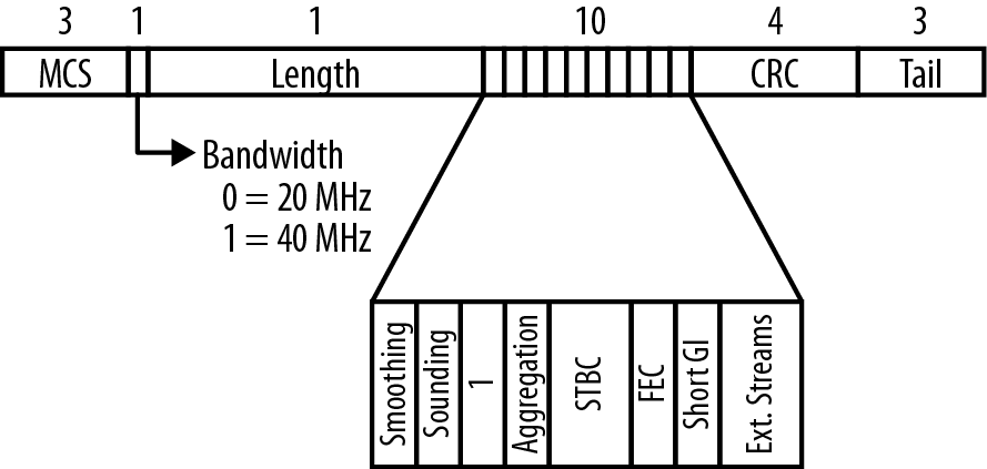
- Modulation and Coding Scheme (7 bits)
This field describes the modulation and coding scheme, and implicitly gives the receiver the number of spatial streams. Although the MCS value can take on any one of 76 values, the 32 described in 802.11n Speed are by far the most commonly used.
- Channel bandwidth (1 bit)
This bit is set to 0 for 20 MHz channels and 1 for 40 MHz channels.
- HT Length (16 bits)
This field describes the length of the PSDU in bytes, and can range up to 65,535.
- Not Sounding (1 bit)
Sounding frames are used in beamforming, a process that is described in more detail in Chapter 4. When this bit is set to 0, the frame is not a sounding frame, which is the typical operation. When set to 1, the frame is used for sounding operations.
- Aggregation (1 bit)
This bit is set when the payload is an aggregate frame that contains several subframes. Aggregation is further described in Chapter 5.
- STBC (2 bits)
Space-Time Block Coding allows multiple radio chains to be used to increase the sensitivity to a single data stream; it is further described in Chapter 4.
- Forward Error Correction coding (1 bit)
When using a convolutional code, this bit is set to 0; to use LDPC, the bit is set to 1.
- Short guard interval (1 bit)
When the short guard interval is in use, this bit is set to 1. When set to 0, it indicates the long guard interval is in use.
- CRC (8 bits)
A CRC allows the receiver to detect corruption of the HT Signal field.
- Tail bits (6 bits)
The HT Signal field is protected by a convolutional code, and requires a trailing six zeroes to “ramp down” the convolutional code.
Data Field
As shown in Figure 3-5, the Data field of the PLCP consists of four components:
- SERVICE field (16 bits)
This field has 16 zeroes to initialize the data scrambler. To avoid long sequences of the same bit, 802.11n uses a scrambler to improve the distribution of ones and zeroes in the payload.
- PSDU (variable)
This field contains the PLCP Service Data Unit, which is a frame from higher protocol layers being prepared for transmission out the radio interface. To improve efficiency, the 802.11n MAC layer may provide an aggregate frame, which is described in Chapter 5.
- Tail bits (6 bits for each encoding stream)
Convolutional coders require tail bits to cleanly terminate the convolutional code. Each encoder requires six bits. Generally speaking, this field will be six bits long, though at speeds greater than 300 Mbps, it is twelve bits.
- Pad bits (variable)
Pad bits are used to ensure that the Data field of the PLCP is an even number of symbols.
Transmission and Reception Process
The block diagram for an 802.11n interface is shown in Figure 3-7. When a frame is ready for transmission, an 802.11n interface runs the following procedure:[18]

Scramble and Forward Error Correction (FEC) encode: The scrambler is a process that reduces the probability of long strings of identical bits before feeding the resulting bits to the FEC encoder. The FEC is either a convolutional coder or an LDPC coder; Figure 3-7 shows two convolutional coders to illustrate that two encoders must be used when the data rate exceeds 300 Mbps.
Stream parsing: The stream parser takes the output of the FEC encoder and divides up the encoded bits between each spatial stream. For example, if there are two spatial streams, the stream parser will take the encoded bits and assign each encoded bit to one of the spatial streams. At this point, the bits flowing from the stream parser to the interleaver are a spatial stream. Output from the stream parser is sent to the interleaver, which is the first component in the radio chain.
Interleave and mapping: As in 802.11a/g, the interleaver changes the order of the bits. Convolutional codes correct errors best when errors are confined to short bursts. The interleaver spreads adjacent bits across OFDM subcarriers to assist the convolutional code in isolating and correcting errors. When bits leave the interleaver, they are mapped on to constellation points for transmission.[19] 802.11n does not alter the constellations used by 802.11a/g.
Space-Time Block Coding (STBC): This optional step, described in more detail in Chapter 4, can be used to transmit one spatial stream across two antennas for extra redundancy. The space-time block coder takes the output of the interleaver/constellation mapper and spreads it across multiple radio chains, transforming the spatial streams into space-time streams.
Spatial mapping: Space-time streams are mapped onto the transmit chains by the spatial mapper. This will often be a direct mapping, in which a spatial stream becomes a space-time stream and then is mapped on to a single transmit chain. Direct mapping is a simple, straightforward process.
As an alternative to direct mapping, the spatial mapper may instead perform a spatial expansion, in which all of the space-time streams from the STBC are spread across all the transmit chains. Spatial expansion is similar to beamforming, in which the space-time streams are “shaped” to direct energy in a particular direction. Beamforming is discussed in more detail in Chapter 4.
Inverse Fourier transform and cyclic shift: Taken together, these two components convert the frequency-domain signal into a time-domain signal suitable for transmission. The inverse Fourier transform takes the frequency-domain data from OFDM and converts it to time-domain data. To preserve the neutral nature of the MIMO transmission, a cyclic shift adds a small phase delay to each transmit chain. The cyclic shift may be added per transmit chain (as shown in Figure 2-3), or it may be added after the space-time streams are created (as shown in Figure 3-7).
Guard insertion and windowing improve the signal quality at the receiver, just as in 802.11a/g.
Finally, the radio section amplifies the signal for transmission out an antenna. At this stage, the final data signal is available and can be placed on to the carrier. A high power amplifier (HPA) increases the power so the signal can travel as far as needed, within regulatory limits.
To receive a frame, the transceiver reverses the steps. A weak signal from the antenna is boosted by a Low-Noise Amplifier (LNA) so that the symbols can be recovered with a Fourier transform. After separating the spatial streams and de-interleaving, errors in the bit stream are corrected by the FEC and the resulting frame is passed to the MAC.
802.11n Speed
Answering the question of “How fast does 802.11n go?” is something that defies a simple explanation. Unlike previous PHYs that had only a handful of options (none of which affected the link rate used) 802.11n has a number of options that together determine the data rate. Almost 2% of the page count of 802.11n is devoted to tables that describe the speed for various options.
This section discusses the speed in 802.11n from the standpoint of a network administrator buying product that is readily available. Two questions will often come to mind. First, how does it compare to pre-802.11n equipment, such as the laptops with 802.11a/g? Second, what types of link rates can I expect to see when I use 802.11n devices?
For simplicity, this section will quote link rates using the long guard interval. It is the default setting on most equipment, and is generally safer to use. The performance boost for switching to the short guard interval about 11%, which is substantial only in environments where the radio channel is saturated. When faced with a bewildering array of choices, most people tend to zero in on a couple of numbers that stick out, and I’ve found that the most commonly cited numbers are the following:
150 Mbps (two spatial streams using 20 MHz channels with a short guard interval at MCS15), because it is the first data rate in the 802.11 world to top 100 Mbps using the traditional 20 MHz channel size
300 Mbps (two spatial streams using 40 MHz channels with a short guard interval at MCS15), because it is the top data rate supported by the first products that saw wide release into the market
450 Mbps (three spatial streams using 40 MHz channels with a short guard interval at MCS15), because it is the top data supported by three-stream 802.11n products. This data rate was widely available in products that began shipping in 2011.
600 Mbps (four spatial streams using 40 MHz channels with a short guard interval at MCS 31), because it is the top data rate described by the 802.11n standard, even if no products based on that data rate have yet been sold.
Comparison 1: 802.11a/g versus 1x1 11n
Many client devices have implemented 802.11n for cost reasons. Once the technology basis for the industry moves, it is hard to get older chips. Even though many battery-powered devices have low overall throughput requirements and therefore, manufacturers would sometimes prefer to keep using 802.11b, chip vendors continuously refresh their product lines and pull their customers towards the latest technology. Even devices made with full attention to reducing battery draw are now made with 802.11n chips, though of course it is a 1x1 design to minimize the number of power-hungry radio chain components. Virtually every Wi-Fi enabled phone uses single-stream 802.11n, as do many tablet computing devices.
In the case of single-stream 802.11n, there is only a small performance gain in link rate. 802.11n’s channel has 8% more data subcarriers in a channel, so it can support link rates that are 8% higher, as shown in Table 3-2. Even though the link rate is not higher on paper, it often makes sense to use 802.11n for these devices because the antenna array at the AP can often boost performance through techniques like maximal ratio combining.
Comparison 2: 20 MHz versus 40 MHz channels
The second comparison that is often made is the difference in link rate between the familiar 20 MHz channel width and the new wider 40 MHz channels in 802.11n. Table 3-3 and Table 3-4 show the link rate that can be achieved for various combinations of modulation, coding, and spatial streams. The table shows data rates using the long guard interval; for speeds using the optional short guard interval, add 11%. In 802.11n, each combination is given an MCS number. These two tables only show the equal modulation MCS numbers; there are many more MCS numbers that make use of unequal modulation, but they are not widely supported.
The first wave of access points and laptops to hit the market supported only two spatial streams, and the common numbers used to describe the performance of these systems was “100 Mbps” (which is the net throughput of a set of frames aggregated together at 135 Mbps, plus a block acknowledgment) or “300 Mbps” (the link rate achieved with 40 MHz channels and a short guard interval).
In 2011, the second major wave of products was brought to market, supporting three spatial streams and speeds of up to 450 Mbps. These products now power all mainstream high-performance access points, and many new client devices now use three-stream 802.11n chipsets. Although four spatial streams have been standardized, it seems unlikely that four-stream products will ever be mainstream because most chip vendors have focused on building four-stream products using 802.11n’s even higher-speed successor.
| Modulation and coding | 1 SS | 2 SS | 3 SS | 4 SS |
| BPSK, R=1/2 | 6.5 (MCS 0) | 13.0 (MCS 8) | 19.5 (MCS 16) | 26.0 (MCS 24) |
| QPSK, R=1/2 | 13.0 (MCS 1) | 26.0 (MCS 9) | 39.0 (MCS 17) | 52.0 (MCS 25) |
| QPSK, R=3/4 | 19.5 (MCS 2) | 39.0 (MCS 10) | 58.5 (MCS 18) | 78.0 (MCS 26) |
| 16-QAM, R=1/2 | 26.0 (MCS 3) | 52.0 (MCS 11) | 78.0 (MCS 19) | 104.0 (MCS 27) |
| 16-QAM, R=3/4 | 39.0 (MCS 4) | 78.0 (MCS 12) | 117.0 (MCS 20) | 156.0 (MCS 28) |
| 64-QAM, R=1/2 | 52.0 (MCS 5) | 104.0 (MCS 13) | 156.0 (MCS 21) | 208.0 (MCS 29) |
| 64-QAM, R=3/4 | 58.5 (MCS 6) | 117.0 (MCS 14) | 175.5 (MCS 22) | 234.0 (MCS 30) |
| 64-QAM, R=5/6 | 65.0 (MCS 7) | 135.0 (MCS 15) | 195.0 (MCS 23) | 260.0 (MCS 31) |
| Modulation and coding | 1 SS | 2 SS | 3 SS | 4 SS |
| BPSK, R=1/2 | 13.5 (MCS 0) | 27.0 (MCS 8) | 40.5 (MCS 16) | 54.0 (MCS 24) |
| QPSK, R=1/2 | 27.0 (MCS 1) | 54.0 (MCS 9) | 81.0 (MCS 17) | 108.0 (MCS 25) |
| QPSK, R=3/4 | 40.5 (MCS 2) | 81.0 (MCS 10) | 121.5 (MCS 18) | 162.0 (MCS 26) |
| 16-QAM, R=1/2 | 54.0 (MCS 3) | 108.0 (MCS 11) | 162.0 (MCS 19) | 216.0 (MCS 27) |
| 16-QAM, R=3/4 | 81.0 (MCS 4) | 162.0 (MCS 12) | 243.0 (MCS 20) | 324.0 (MCS 28) |
| 64-QAM, R=1/2 | 108.0 (MCS 5) | 216.0 (MCS 13) | 324.0 (MCS 21) | 432.0 (MCS 29) |
| 64-QAM, R=3/4 | 121.5 (MCS 6) | 243.0 (MCS 14) | 364.5 (MCS 22) | 486.0 (MCS 30) |
| 64-QAM, R=5/6 | 135.0 (MCS 7) | 270.0 (MCS 15) | 405.0 (MCS 23) | 540.0 (MCS 31) |
Mandatory PHY Features
802.11n is a complex specification, with many protocol features. To help readers keep track of features that are mandatory and optional, Table 3-5 classifies the protocol features into two categories. Generally speaking, the Wi-Fi Alliance test plan validates functionality which is mandatory in the specification and has optional testing only for the most widely supported features.
| Feature | Mandatory/optional? | Comments |
| HT-Mixed Mode | Mandatory | |
| HT-Greenfield mode | Optional | Validated in Wi-Fi Alliance test plan; supported by approximately 1/4 of certified devices. |
| 800 ns guard interval | Mandatory | |
| 400 ns (short) guard interval | Optional | Validated in Wi-Fi Alliance test plan and displayed on interoperability certificate; supported by approximately 3/4 of devices |
| 20 MHz channel operation | Mandatory | |
| 40 MHz channel operation | Optional | Validated by Wi-Fi Alliance test plan and displayed on interoperability certificate. Only about 1/4 of devices support 2.4 GHz operation with coexistence mechanisms; about 3/4 of enterprise APs support 40 MHz channels in 5 GHz |
| Single-stream operation (MCS 0 through MCS 7) | Mandatory | Wi-Fi Alliance test plan only requires 1-stream operation by client devices. |
| 2-stream operation (MCS 8 through MCS 15) | Mandatory for APs | 2-stream operation is required for all APs. The number of spatial streams tested is displayed on the interoperability certificate. |
| 3- and 4-stream operation (MCS 16 through MCS 31) | Optional | 3-stream enterprise APs are mainstream and are tested by the Wi-Fi Alliance; very few 4-stream APs exist, and 4-stream operation is untested |
| HT Duplicate Mode (MCS 32) | Optional | MCS 32, also called HT Duplicate mode, uses a single 40 MHz channel with one spatial stream at a data rate of 6 Mbps. It is very conservatively coded for high reliability. Because the speed is quite slow, however, it is not widely used in large-scale networks. |
| MCS 33 through MCS 76 (unequal modulation) | Optional | |
| Transmit Beamforming | Optional | Not part of Wi-Fi Alliance test plan. See Chapter 4 |
| Low-density Parity Check | Optional | Not part of Wi-Fi Alliance test plan. See Chapter 4 |
| Space-Time Block Coding | Optional | Validated by Wi-Fi Alliance test plan and displayed on the interoperability certificate, but supported by less than 1/5 of certified 11n devices. See Chapter 4. |
[12] For an introduction to the use of OFDM in 802.11a/g, see Chapter 13 in 802.11 Wireless Networks: The Definitive Guide.
[13] Potentially confusingly, the operation of 802.11n in the 2.4 GHz band is generally called 802.11ng, while operation of 802.11n in the 5 GHz band is generally called 802.11na.
[14] 802.11 defined several protocol operations to support the use of DFS, most notably in the 802.11d and 802.11h amendments.
[15] Puncturing a convolutional code to achieve a higher rate code is described in Figure 13-10 of my earlier book, 802.11 Wireless Networks: The Definitive Guide (O’Reilly). That figure illustrates how to puncture the output of a R=1/2 code to achieve R=2/3. To achieve R=5/6 from the output of an R=1/2 encoder, more of the data is discarded during the puncturing process.
[16] The guard interval is a common component of OFDM system design. For more background on the rationale behind the guard interval, see Chapter 13 of 802.11 Wireless Networks: The Definitive Guide.
[17] See, for example, Figure 13-14 in 802.11 Wireless Networks: The Definitive Guide.
[18] In many ways, the transmission procedure for 802.11n resembles that for the OFDM physical layers used in 802.11a and 802.11g. For more information, see Chapter 13 in 802.11 Wireless Networks: The Definitive Guide.
[19] Constellation mapping and modulation is a complex topic. For a bit more background with pictures, see my video about QAM and error vector magnitude.