
i
i
i
i
i
i
i
i
9
Image-Based
Rendering
Image-based rendering (IBR) techniques are a powerful alternative to tradi-
tional geometry-based techniques for creating images. Instead of using basic
geometric primitives, a collection of sample images are used to render novel
views.
In Chapter 5, we discussed these traditional techniques and looked
at how 3D scenes constructed from polygonal models were stored in data-
bases. Then, in Chapter 7, which explored the 3D rendering pipeline, we
made the implicit assumption that the view one sees in a 3D scene arises as
the result of rendering these polygonal models. And for the majority of VR
applications, this assumption is probably true. However, IBR offers us an
alternative way to set up and visualize a virtual world that does not involve
rendering polygons and doesn’t require any special 3D accelerated hardware.
Fortunately, we have already touched upon the techniques of IBR in Sec-
tion 8.3.5 when we discussed panoramic image composition, and we also
covered one of its most fundamental ideas (that is, removing perspective dis-
tortion) in Section 8.3.2.
Of course, there is a lot more to IBR than just allowing one to render
views of a virtual world made up of a collection of photographs as opposed
to a collection of polygonal models. In this chapter, w e will allo w ourselves a
little indulgence to briefly explore some of these exciting ideas before focusing
primarily on those aspects of IBR most relevant to VR. In some situations,
IBR is a much more relevant technology to use for VR because it actually
allows us to use photographs of real places, and this can make a virtual scene
seem anything but virtual!
219

i
i
i
i
i
i
i
i
220 9. Image-Based Rendering
9.1 General Approaches to IBR
It is generally accepted that there are three different classifications of IBR,
which are based on the significance of the geometric component involved in
the rendering process [17]. These are:
1. Rendering with no geometry. Hypothetically, it is possible to envision
storing a complete description of a 3D scene using a seven-dimensional
function that gives the light intensity at every point of space (three
dimensions x, y, z), looking in every direction (another two dimen-
sions
, ), at all times t and for every wavelength of light .Adelson
and Bergen [1] gave this function the name plenoptic,
p = P(x, y, z,
, , t, ). Plenoptic modeling is the general name given
to any approach to rendering that may be expressed in these terms.
For example, environment mapping as described in Section 7.6.2 is
a function of two variables p = P(
, ), viewed from a single point, at
a single instant in time and under fixed lighting conditions. That is,
x, y, z, t and
are constant.
It is impractical to work with a seven-dimensional scene, but a four-
dimensional plenoptic model such as the lumigraph [7] will allow a
view in any direction to be determined from any point on a surface
surrounding a convex object. The four dimensions are the two surface
coordinates (u, v) and two angular directions of view, up/down (
) and
left/right ( ). That is, p = P(u, v, , ). The lumigraph is illustrated
in Figure 9.1. The lumigraph attempts to capture the image that would
be seen at every point and by looking in every direction on the surface
of a box that surrounds an object. In practice, the surface of the box
is divided up into little patches (e.g., 32 × 32 on each side), and for
each patch, a finite number of images (e.g., 256 × 256) are made by
looking in a range of directions that span a wide angle. One of the
advantages of this concept is that it allows parallax and stereoscopic
effects to be easily and quickly rendered. In addition, the reduction
to four degrees of freedom, appropriate discretization and compression
reduce the scene description data size even further.
Apple’s QuickTime VR [3] and Shum and Szeliski’s [18] method are
also examples of the use of no-geometry plenoptic functions. In this
case, they are functions of two variables, and so they have manageable
data requirements and very high rendering speeds. Shum and Szeliski’s

i
i
i
i
i
i
i
i
9.1. General Approaches to IBR 221
Figure 9.1. The concept of the lumigraph.
Figure 9.2. The viewing frustum for rendering from an environment map. In (a), a
cubic environment is shown, and in (b) a spherical one. Note the distortion on the
spherical map and the requirement to use parts of two or three sides of the cube.
method of capturing image panoramas has been used to provide envi-
ronment maps for a number of the sample programs in Direct3D SDK
(which we discuss in Chapter 13). Both these methods render their
output by working from a panoramic image stitched together from a
collection of photographs. Rendering can be done by traditional spher-
ical or cubic environment maps (see Figure 9.2), which can take advan-
tage of hardware acceleration if it’s available, or by a highly optimized
image texture lookup function using direction of view input parame-
ters. More interesting perhaps is how the panoramas are produced. We
will look at these methods in more detail shortly.
2. Rendering with implicit geometry. This class of methods gets its name
because it uses inferred geometric properties of the scene which arise
i
i
i
i
i
i
i
i
222 9. Image-Based Rendering
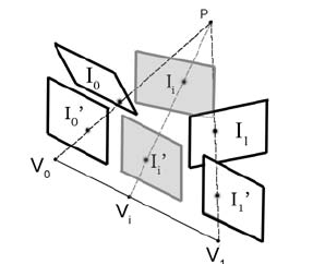
Figure 9.3. Viewmorph. Original images I
0
and I
1
are projected on a plane at I
0
and
I
1
respectively. Both these images lie in the same plane, and an interpolation between
them will give an image I
i
. If required, a reprojection to the image plane I
i
can be
made.
from the usual projection calculations of conventional rendering; e.g.,
using field of view, aspect ratio or frustum. Chen and Williams [5]
introduced the idea of image morphing among several photographs
taken of a scene. They used range data to obtain the correspondences
between the images. Seitz and Dyer [16] show how, given two pho-
tographs of a scene and the location and direction of view in each, it
is possible to re-create an apparent view from a point between the two
locations. Their algorithm consists of three stages, as depicted in Fig-
ure 9.3. First the two images are projected onto a common plane, then
common points are interpolated to give the desired image and finally
the interpolated image is re-projected to giv e the desired viewpoint.
3. Rendering with explicit geometry. Often some range data (depth in-
formation a long line of sight, possibly obtained with a laser scanner)
is available along with a photographic image. In this case, McMil-
lan [12] demonstrated that photographs, apparently taken from loca-
tions nearby where no photographic images are available, can be gener-
ated synthetically. This is done by projecting the pixels from the images
into their 3D locations and then reprojecting them to give a new view.
The biggest problems with this are holes due to differences in sampling
resolutions in the input and output images and occlusions where an
object would be visible in the output image but is hidden in the input
images. Figure 9.4 illustrates the idea using only one source image.

i
i
i
i
i
i
i
i
9.2. Acquiring Images for IBR 223
Figure 9.4. Depth rendering. When the distance from the camera to an object’s
surface is known, a 3D model can be constr ucted. This can be rendered from a
different direction, but note that points on the object’s surface which are not visible
from one camera location may be visible from another, and since they can’t be seen
from the location where the range is detected, holes will result in the alternate view.
In VR, the most useful IBR methods are the 2D no geometry plenop-
tic functions of item 1. In the rest of this chapter, we will look at how the
panoramic images they use are produced and applied in real-time virtual en-
vironment navigation applications.
9.2 Acquiring Images for IBR
One of the trickiest things to do in IBR is acquire the images that are to be
used to construct the panoramic view or omnidirectional object views ren-
dered in response to a specified direction of view. Ultimately, one would
really like to be able to construct these by using a handheld video camera and
making a rough scan of the complete enveloping environment. This would
require significant analytical effort in the subsequent image processing stage,
termed mosaicing. Alternatively, special-purpose imaging hardware has been
developed, such as that by Matusik et al. [11]. They use this hardware to
acquire images of objects under highly controlled lighting conditions. Equip-
ment of this type is illustrated in Figure 9.5(a).
A camera mounted on a tripod can be used to obtain 360
◦
panoramas
(the concept of which is illustrated in Figure 8.14). However, problems arise
if one tries to capture images directly overhead. In this case, the production
of the complete panorama can be challenging. To increase the v ertical field of
view, a camera can be mounted sideways. This was suggested by Apple Com-
puter as one way to prepare a panoramic movie for use in QuickTime VR
..................Content has been hidden....................
You can't read the all page of ebook, please click here login for view all page.