
EXCEPTION AND INTERRUPT HANDLING
At the heart of an embedded system lie the exception handlers. They are responsible for handling errors, interrupts, and other events generated by the external system. Efficient handlers can dramatically improve system performance. The process of determining a good handling method can be complicated, challenging, and fun.
In this chapter we will cover the theory and practice of handling exceptions, and specifically the handling of interrupts on the ARM processor. The ARM processor has seven exceptions that can halt the normal sequential execution of instructions: Data Abort, Fast Interrupt Request, Interrupt Request, Prefetch Abort, Software Interrupt, Reset, and Undefined Instruction.
This chapter is divided into three main sections:
![]() Exception handling. Exception handling covers the specific details of how the ARM processor handles exceptions.
Exception handling. Exception handling covers the specific details of how the ARM processor handles exceptions.
![]() Interrupts. ARM defines an interrupt as a special type of exception. This section discusses the use of interrupt requests, as well as introducing some of the common terms, features, and mechanisms surrounding interrupt handling.
Interrupts. ARM defines an interrupt as a special type of exception. This section discusses the use of interrupt requests, as well as introducing some of the common terms, features, and mechanisms surrounding interrupt handling.
![]() Interrupt handling schemes. The final section provides a set of interrupt handling methods. Included with each method is an example implementation.
Interrupt handling schemes. The final section provides a set of interrupt handling methods. Included with each method is an example implementation.
9.1 EXCEPTION HANDLING
An exception is any condition that needs to halt the normal sequential execution of instructions. Examples are when the ARM core is reset, when an instruction fetch or memory access fails, when an undefined instruction is encountered, when a software interrupt instruction is executed, or when an external interrupt has been raised. Exception handling is the method of processing these exceptions.
Most exceptions have an associated software exception handler—a software routine that executes when an exception occurs. For instance, a Data Abort exception will have a Data Abort handler. The handler first determines the cause of the exception and then services the exception. Servicing takes place either within the handler or by branching to a specific service routine. The Reset exception is a special case since it is used to initialize an embedded system.
This section covers the following exception handling topics:
9.1.1 ARM PROCESSOR EXCEPTIONS AND MODES
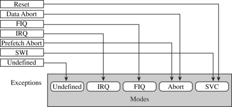
Table 9.1 lists the ARM processor exceptions. Each exception causes the core to enter a specific mode. In addition, any of the ARM processor modes can be entered manually by changing the cpsr. User and system mode are the only two modes that are not entered by a corresponding exception, in other words, to enter these modes you must modify the cpsr. When an exception causes a mode change, the core automatically
Table 9.1
ARM processor exceptions and associated modes.
| Exception | Mode | Main purpose |
| Fast Interrupt Request | FIQ | fast interrupt request handling |
| Interrupt Request | IRQ | interrupt request handling |
| SWI and Reset | SVC | protected mode for operating systems |
| Prefetch Abort and Data Abort | abort | virtual memory and/or memory protection handling |
| Undefined Instruction | undefined | software emulation of hardware coprocessors |
![]() saves the cpsr to the spsr of the exception mode
saves the cpsr to the spsr of the exception mode
![]() saves the pc to the lr of the exception mode
saves the pc to the lr of the exception mode
Figure 9.1 shows a simplified view of exceptions and associated modes. Note that when an exception occurs the ARM processor always switches to ARM state.
9.1.2 VECTOR TABLE
Chapter 2 introduced the vector table—a table of addresses that the ARM core branches to when an exception is raised. These addresses commonly contain branch instructions of one of the following forms:
![]() B <address>—This branch instruction provides a branch relative from the pc.
B <address>—This branch instruction provides a branch relative from the pc.
![]() LDR pc, [pc, #offset]—This load register instruction loads the handler address from memory to the pc. The address is an absolute 32-bit value stored close to the vector table. Loading this absolute literal value results in a slight delay in branching to a specific handler due to the extra memory access. However, you can branch to any address in memory.
LDR pc, [pc, #offset]—This load register instruction loads the handler address from memory to the pc. The address is an absolute 32-bit value stored close to the vector table. Loading this absolute literal value results in a slight delay in branching to a specific handler due to the extra memory access. However, you can branch to any address in memory.
![]() LDR pc, [pc, #-0xff0]—This load register instruction loads a specific interrupt service routine address from address 0xfffff030 to the pc. This specific instruction is only used when a vector interrupt controller is present (VIC PL190).
LDR pc, [pc, #-0xff0]—This load register instruction loads a specific interrupt service routine address from address 0xfffff030 to the pc. This specific instruction is only used when a vector interrupt controller is present (VIC PL190).
![]() MOV pc, #immediate—This move instruction copies an immediate value into the pc. It lets you span the full address space but at limited alignment. The address must be an 8-bit immediate rotated right by an even number of bits.
MOV pc, #immediate—This move instruction copies an immediate value into the pc. It lets you span the full address space but at limited alignment. The address must be an 8-bit immediate rotated right by an even number of bits.
You can also have other types of instructions in the vector table. For example, the FIQ handler might start at address offset +0x1c. Thus, the FIQ handler can start immediately at the FIQ vector location, since it is at the end of the vector table. The branch instructions cause the pc to jump to a specific location that can handle the specific exception.
Table 9.2 shows the exception, mode, and vector table offset for each exception.
Table 9.2
Vector table and processor modes.
| Exception | Mode | Vector table offset |
| Reset | SVC | +0x00 |
| Undefined Instruction | UND | +0x04 |
| Software Interrupt (SWI) | SVC | +0x08 |
| Prefetch Abort | ABT | +0x0c |
| Data Abort | ABT | +0x10 |
| Not assigned | — | +0x14 |
| IRQ | IRQ | +0x18 |
| FIQ | FIQ | +0x1c |
EXAMPLE 9.1
Figure 9.2 shows a typical vector table. The Undefined Instruction entry is a branch instruction to jump to the undefined handler. The other vectors use an indirect address jump with the LDR load to pc instruction.
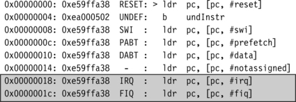
Notice that the FIQ handler also uses the LDR load to pc instruction and does not take advantage of the fact that the handler can be placed at the FIQ vector entry location.
9.1.3 EXCEPTION PRIORITIES
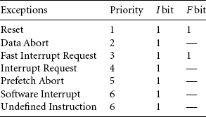
Exceptions can occur simultaneously, so the processor has to adopt a priority mechanism. Table 9.3 shows the various exceptions that occur on the ARM processor and their associated priority level. For instance, the Reset exception is the highest priority and occurs when power is applied to the processor. Thus, when a reset occurs, it takes precedence over all other exceptions. Similarly, when a Data Abort occurs, it takes precedence over all other exceptions apart from a Reset exception. The lowest priority level is shared by two exceptions, the Software Interrupt and Undefined Instruction exceptions. Certain exceptions also disable interrupts by setting the I or F bits in the cpsr, as shown in Table 9.3.
Each exception is dealt with according to the priority level set out in Table 9.3. The following is a summary of the exceptions and how they should be handled, starting with the highest.
The Reset exception is the highest priority exception and is always taken whenever it is signaled. The reset handler initializes the system, including setting up memory and caches. External interrupt sources should be initialized before enabling IRQ or FIQ interrupts to avoid the possibility of spurious interrupts occurring before the appropriate handler has been set up. The reset handler must also set up the stack pointers for all processor modes.
During the first few instructions of the handler, it is assumed that no exceptions or interrupts will occur. The code should be designed to avoid SWIs, undefined instructions, and memory accesses that may abort, that is, the handler is carefully implemented to avoid further triggering of an exception.
Data Abort exceptions occur when the memory controller or MMU indicates that an invalid memory address has been accessed (for example, if there is no physical memory for an address) or when the current code attempts to read or write to memory without the correct access permissions. An FIQ exception can be raised within a Data Abort handler since FIQ exceptions are not disabled. When the FIQ is completely serviced, control is returned back to the Data Abort handler.
A Fast Interrupt Request (FIQ) exception occurs when an external peripheral sets the FIQ pin to nFIQ. An FIQ exception is the highest priority interrupt. The core disables both IRQ and FIQ exceptions on entry into the FIQ handler. Thus, no external source can interrupt the processor unless the IRQ and/or FIQ exceptions are reenabled by software. It is desirable that the FIQ handler (and also the abort, SWI, and IRQ handlers) is carefully designed to service the exception efficiently.
An Interrupt Request (IRQ) exception occurs when an external peripheral sets the IRQ pin to nIRQ. An IRQ exception is the second-highest priority interrupt. The IRQ handler will be entered if neither an FIQ exception nor Data Abort exception occurs. On entry to the IRQ handler, the IRQ exceptions are disabled and should remain disabled until the current interrupt source has been cleared.
A Prefetch Abort exception occurs when an attempt to fetch an instruction results in a memory fault. This exception is raised when the instruction is in the execute stage of the pipeline and if none of the higher exceptions have been raised. On entry to the handler, IRQ exceptions will be disabled, but the FIQ exceptions will remain unchanged. If FIQ is enabled and an FIQ exception occurs, it can be taken while servicing the Prefetch Abort.
A Software Interrupt (SWI) exception occurs when the SWI instruction is executed and none of the other higher-priority exceptions have been flagged. On entry to the handler, the cpsr will be set to supervisor mode.
If the system uses nested SWI calls, the link register r14 and spsr must be stored away before branching to the nested SWI to avoid possible corruption of the link register and the spsr.
An Undefined Instruction exception occurs when an instruction not in the ARM or Thumb instruction set reaches the execute stage of the pipeline and none of the other exceptions have been flagged. The ARM processor “asks” the coprocessors if they can handle this as a coprocessor instruction. Since coprocessors follow the pipeline, instruction identification can take place in the execute stage of the core. If none of the coprocessors claims the instruction, an Undefined Instruction exception is raised.
Both the SWI instruction and Undefined Instruction have the same level of priority, since they cannot occur at the same time (in other words, the instruction being executed cannot both be an SWI instruction and an undefined instruction).
9.1.4 LINK REGISTER OFFSETS
When an exception occurs, the link register is set to a specific address based on the current pc. For instance, when an IRQ exception is raised, the link register lr points to the last executed instruction plus 8. Care has to be taken to make sure the exception handler does not corrupt lr because lr is used to return from an exception handler. The IRQ exception is taken only after the current instruction is executed, so the return address has to point to the next instruction, or lr – 4. Table 9.4 provides a list of useful addresses for the different exceptions.
Table 9.4
Useful link-register-based addresses.
| Exception | Address | Use |
| Reset | — | lr is not defined on a Reset |
| Data Abort | lr – 8 | points to the instruction that caused the Data Abort exception |
| FIQ | lr – 4 | return address from the FIQ handler |
| IRQ | lr – 4 | return address from the IRQ handler |
| Prefetch Abort | lr – 4 | points to the instruction that caused the Prefetch Abort exception |
| SWI | lr | points to the next instruction after the SWI instruction |
| Undefined Instruction | lr | points to the next instruction after the undefined instruction |
The next three examples show different methods of returning from an IRQ or FIQ exception handler.
EXAMPLE 9.2
This example shows that a typical method of returning from an IRQ and FIQ handler is to use a SUBS instruction:
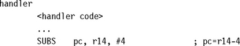
Because there is an S at the end of the SUB instruction and the pc is the destination register, the cpsr is automatically restored from the spsr register.
EXAMPLE 9.3
This example shows another method that subtracts the offset from the link register r14 at the beginning of the handler.
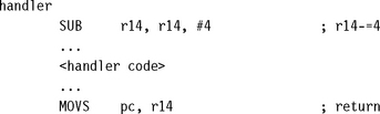
After servicing is complete, return to normal execution occurs by moving the link register r14 into the pc and restoring cpsr from the spsr.
EXAMPLE 9.4
The final example uses the interrupt stack to store the link register. This method first subtracts an offset from the link register and then stores it onto the interrupt stack.
![]()
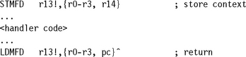
To return to normal execution, the LDM instruction is used to load the pc. The ^ symbol in the instruction forces the cpsr to be restored from the spsr.
9.2 INTERRUPTS
There are two types of interrupts available on the ARM processor. The first type of interrupt causes an exception raised by an external peripheral—namely, IRQ and FIQ. The second type is a specific instruction that causes an exception—the SWI instruction. Both types suspend the normal flow of a program.
In this section we will focus mainly on IRQ and FIQ interrupts. We will cover these topics:
9.2.1 ASSIGNING INTERRUPTS
A system designer can decide which hardware peripheral can produce which interrupt request. This decision can be implemented in hardware or software (or both) and depends upon the embedded system being used.
An interrupt controller connects multiple external interrupts to one of the two ARM interrupt requests. Sophisticated controllers can be programmed to allow an external interrupt source to cause either an IRQ or FIQ exception.
When it comes to assigning interrupts, system designers have adopted a standard design practice:
![]() Software Interrupts are normally reserved to call privileged operating system routines. For example, an SWI instruction can be used to change a program running in user mode to a privileged mode. For an SWI handler example, take a look at Chapter 11.
Software Interrupts are normally reserved to call privileged operating system routines. For example, an SWI instruction can be used to change a program running in user mode to a privileged mode. For an SWI handler example, take a look at Chapter 11.
![]() Interrupt Requests are normally assigned for general-purpose interrupts. For example, a periodic timer interrupt to force a context switch tends to be an IRQ exception. The IRQ exception has a lower priority and higher interrupt latency (to be discussed in the next section) than the FIQ exception.
Interrupt Requests are normally assigned for general-purpose interrupts. For example, a periodic timer interrupt to force a context switch tends to be an IRQ exception. The IRQ exception has a lower priority and higher interrupt latency (to be discussed in the next section) than the FIQ exception.
![]() Fast Interrupt Requests are normally reserved for a single interrupt source that requires a fast response time—for example, direct memory access specifically used to move blocks of memory. Thus, in an embedded operating system design, the FIQ exception is used for a specific application, leaving the IRQ exception for more general operating system activities.
Fast Interrupt Requests are normally reserved for a single interrupt source that requires a fast response time—for example, direct memory access specifically used to move blocks of memory. Thus, in an embedded operating system design, the FIQ exception is used for a specific application, leaving the IRQ exception for more general operating system activities.
9.2.2 INTERRUPT LATENCY
Interrupt-driven embedded systems have to fight a battle with interrupt latency—the interval of time from an external interrupt request signal being raised to the first fetch of an instruction of a specific interrupt service routine (ISR).
Interrupt latency depends on a combination of hardware and software. System architects must balance the system design to handle multiple simultaneous interrupt sources and minimize interrupt latency. If the interrupts are not handled in a timely manner, then the system will exhibit slow response times.
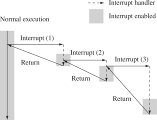
Software handlers have two main methods to minimize interrupt latency. The first method is to use a nested interrupt handler, which allows further interrupts to occur even when currently servicing an existing interrupt (see Figure 9.3). This is achieved by reenabling the interrupts as soon as the interrupt source has been serviced (so it won’t generate more interrupts) but before the interrupt handling is complete. Once a nested interrupt has been serviced, then control is relinquished to the original interrupt service routine.
The second method involves prioritization. You program the interrupt controller to ignore interrupts of the same or lower priority than the interrupt you are handling, so only a higher-priority task can interrupt your handler. You then reenable interrupts.
The processor spends time in the lower-priority interrupts until a higher-priority interrupt occurs. Therefore higher-priority interrupts have a lower average interrupt latency than the lower-priority interrupts, which reduces latency by speeding up the completion time on the critical time-sensitive interrupts.
9.2.3 IRQ AND FIQ EXCEPTIONS
IRQ and FIQ exceptions only occur when a specific interrupt mask is cleared in the cpsr. The ARM processor will continue executing the current instruction in the execution stage of the pipeline before handling the interrupt—an important factor in designing a deterministic interrupt handler since some instructions require more cycles to complete the execution stage.
An IRQ or FIQ exception causes the processor hardware to go through a standard procedure (provided the interrupts are not masked):
1. The processor changes to a specific interrupt request mode, which reflects the interrupt being raised.
2. The previous mode’s cpsr is saved into the spsr of the new interrupt request mode.
3. The pc is saved in the lr of the new interrupt request mode.
4. Interrupt/s are disabled—either the IRQ or both IRQ and FIQ exceptions are disabled in the cpsr. This immediately stops another interrupt request of the same type being raised.
5. The processor branches to a specific entry in the vector table.
The procedure varies slightly depending upon the type of interrupt being raised. We will illustrate both interrupts with an example. The first example shows what happens when an IRQ exception is raised, and the second example shows what happens when an FIQ exception is raised.
EXAMPLE 9.5
Figure 9.4 shows what happens when an IRQ exception is raised when the processor is in user mode. The processor starts in state 1. In this example both the IRQ and FIQ exception bits in the cpsr are enabled.
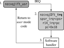
When an IRQ occurs the processor moves into state 2. This transition automatically sets the IRQ bit to one, disabling any further IRQ exceptions. The FIQ exception, however, remains enabled because FIQ has a higher priority and therefore does not get disabled when a low-priority IRQ exception is raised. The cpsr processor mode changes to IRQ mode. The user mode cpsr is automatically copied into spsr_irq.
Register r14_irq is assigned the value of the pc when the interrupt was raised. The pc is then set to the IRQ entry +0x18 in the vector table.
In state 3 the software handler takes over and calls the appropriate interrupt service routine to service the source of the interrupt. Upon completion, the processor mode reverts back to the original user mode code in state 1.
EXAMPLE 9.6
Figure 9.5 shows an example of an FIQ exception. The processor goes through a similar procedure as with the IRQ exception, but instead of just masking further IRQ exceptions from occurring, the processor also masks out further FIQ exceptions. This means that both interrupts are disabled when entering the software handler in state 3.
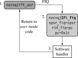
Changing to FIQ mode means there is no requirement to save registers r8 to r12 since these registers are banked in FIQ mode. These registers can be used to hold temporary data, such as buffer pointers or counters. This makes FIQ ideal for servicing a single-source, high-priority, low-latency interrupt.
9.2.3.1 Enabling and Disabling FIQ and IRQ Exceptions
The ARM processor core has a simple procedure to manually enable and disable interrupts that involves modifying the cpsr when the processor is in a privileged mode.
Table 9.5 shows how IRQ and FIQ interrupts are enabled. The procedure uses three ARM instructions.
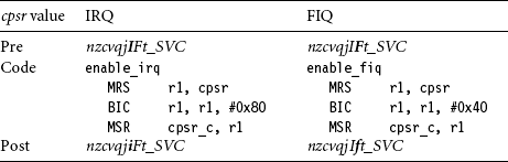
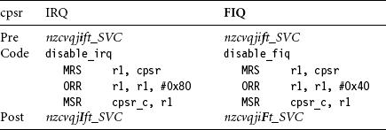
The first instruction MRS copies the contents of the cpsr into register r1. The second instruction clears the IRQ or FIQ mask bit. The third instruction then copies the updated contents in register r1 back into the cpsr, enabling the interrupt request. The postfix _c identifies that the bit field being updated is the control field bit [7:0] of the cpsr. (For more details see Chapter 2.) Table 9.6 shows a similar procedure to disable or mask an interrupt request.
It is important to understand that the interrupt request is either enabled or disabled only once the MSR instruction has completed the execution stage of the pipeline. Interrupts can still be raised or masked prior to the MSR completing this stage.
To enable and disable both the IRQ and FIQ exceptions requires a slight modification to the second instruction. The immediate value on the data processing BIC or ORR instruction has to be changed to 0xc0 to enable or disable both interrupts.
9.2.4 BASIC INTERRUPT STACK DESIGN AND IMPLEMENTATION
Exceptions handlers make extensive use of stacks, with each mode having a dedicated register containing the stack pointer. The design of the exception stacks depends upon these factors:
![]() Operating system requirements—Each operating system has its own requirements for stack design.
Operating system requirements—Each operating system has its own requirements for stack design.
![]() Target hardware—The target hardware provides a physical limit to the size and positioning of the stack in memory.
Target hardware—The target hardware provides a physical limit to the size and positioning of the stack in memory.
Two design decisions need to be made for the stacks:
![]() The location determines where in the memory map the stack begins. Most ARM-based systems are designed with a stack that descends downwards, with the top of the stack at a high memory address.
The location determines where in the memory map the stack begins. Most ARM-based systems are designed with a stack that descends downwards, with the top of the stack at a high memory address.
![]() Stack size depends upon the type of handler, nested or nonnested. A nested interrupt handler requires more memory space since the stack will grow with the number of nested interrupts.
Stack size depends upon the type of handler, nested or nonnested. A nested interrupt handler requires more memory space since the stack will grow with the number of nested interrupts.
A good stack design tries to avoid stack overflow—where the stack extends beyond the allocated memory—because it causes instability in embedded systems. There are software techniques that identify overflow and that allow corrective measures to take place to repair the stack before irreparable memory corruption occurs. The two main methods are (1) to use memory protection and (2) to call a stack check function at the start of each routine.
The IRQ mode stack has to be set up before interrupts are enabled—normally in the initialization code for the system. It is important that the maximum size of the stack is known in a simple embedded system, since the stack size is reserved in the initial stages of boot-up by the firmware.
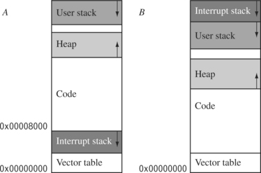
Figure 9.6 shows two typical memory layouts in a linear address space. The first layout, A, shows a traditional stack layout with the interrupt stack stored underneath the code segment. The second layout, B, shows the interrupt stack at the top of the memory above the user stack. The main advantage of layout B over A is that B does not corrupt the vector table when a stack overflow occurs, and so the system has a chance to correct itself when an overflow has been identified.
EXAMPLE 9.7
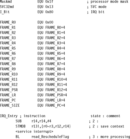
For each processor mode a stack has to be set up. This is carried out every time the processor is reset. Figure 9.7 shows an implementation using layout A. To help set up the memory layout, a set of defines are declared that map the memory region names with an absolute address.
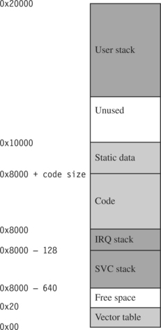
For instance, the User stack is given the label USR_Stack and is set to address 0x20000. The Supervisor stack is set to an address that is 128 bytes below the IRQ stack.
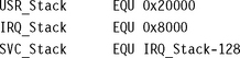
To help change to the different processor modes, we declare a set of defines that map each processor mode with a particular mode bit pattern. These labels can then be used to set the cpsr to a new mode.
For safety reasons a define is declared to disable both the IRQ and FIQ exceptions in the cpsr:
![]()
NoInt masks both interrupts by setting the masks to one.
Initialization code starts by setting up the stack registers for each processor mode. The stack register r13 is one of the registers that is always banked when a mode change occurs. The code first initializes the IRQ stack. For safety reasons, it is always best to make sure that interrupts are disabled by using a bitwise OR between NoInt and the new mode.
Each mode stack must be set up. Here is an example of how to set up three different stacks when the processor core comes out of reset. Note that, since this is a basic example, we do not implement a stack for the abort, FIQ, and undefined instruction modes. If these stacks are required, then very similar code is used.
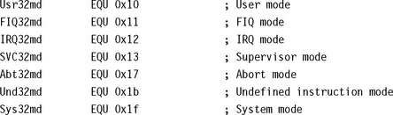
![]() Supervisor mode stack—The processor core starts in supervisor mode so the SVC stack setup involves loading register r13_svc with the address pointed to by SVC_NewStack. For this example the value is SVC_Stack.
Supervisor mode stack—The processor core starts in supervisor mode so the SVC stack setup involves loading register r13_svc with the address pointed to by SVC_NewStack. For this example the value is SVC_Stack.
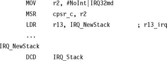
![]() IRQ mode stack—To set up the IRQ stack, the processor mode has to change to IRQ mode. This is achieved by storing a cpsr bit pattern into register r2. Register r2 is then copied into the cpsr, placing the processor into IRQ mode. This action immediately makes register r13_irq viewable, and it can then be assigned the IRQ_Stack value.
IRQ mode stack—To set up the IRQ stack, the processor mode has to change to IRQ mode. This is achieved by storing a cpsr bit pattern into register r2. Register r2 is then copied into the cpsr, placing the processor into IRQ mode. This action immediately makes register r13_irq viewable, and it can then be assigned the IRQ_Stack value.
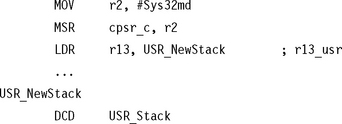
![]() User mode stack—It is common for the user mode stack to be the last to be set up because when the processor is in user mode there is no direct method to modify the cpsr. An alternative is to force the processor into system mode to set up the user mode stack since both modes share the same registers.
User mode stack—It is common for the user mode stack to be the last to be set up because when the processor is in user mode there is no direct method to modify the cpsr. An alternative is to force the processor into system mode to set up the user mode stack since both modes share the same registers.
Using separate stacks for each mode rather than processing using a single stack has one main advantage: errant tasks can be debugged and isolated from the rest of the system.
9.3 INTERRUPT HANDLING SCHEMES
In this final section we will introduce a number of different interrupt handling schemes, ranging from the simple nonnested interrupt handler to the more complex grouped prioritized interrupt handler. Each scheme is presented as a reference with a general description plus an example implementation.
The schemes covered are the following:
![]() A nonnested interrupt handler handles and services individual interrupts sequentially. It is the simplest interrupt handler.
A nonnested interrupt handler handles and services individual interrupts sequentially. It is the simplest interrupt handler.
![]() A nested interrupt handler handles multiple interrupts without a priority assignment.
A nested interrupt handler handles multiple interrupts without a priority assignment.
![]() A reentrant interrupt handler handles multiple interrupts that can be prioritized.
A reentrant interrupt handler handles multiple interrupts that can be prioritized.
![]() A prioritized simple interrupt handler handles prioritized interrupts.
A prioritized simple interrupt handler handles prioritized interrupts.
![]() A prioritized standard interrupt handler handles higher-priority interrupts in a shorter time than lower-priority interrupts.
A prioritized standard interrupt handler handles higher-priority interrupts in a shorter time than lower-priority interrupts.
![]() A prioritized direct interrupt handler handles higher-priority interrupts in a shorter time and goes directly to a specific service routine.
A prioritized direct interrupt handler handles higher-priority interrupts in a shorter time and goes directly to a specific service routine.
![]() A prioritized grouped interrupt handler is a mechanism for handling interrupts that are grouped into different priority levels.
A prioritized grouped interrupt handler is a mechanism for handling interrupts that are grouped into different priority levels.
![]() A VIC PL190 based interrupt service routine shows how the vector interrupt controller (VIC) changes the design of an interrupt service routine.
A VIC PL190 based interrupt service routine shows how the vector interrupt controller (VIC) changes the design of an interrupt service routine.
9.3.1 NONNESTED INTERRUPT HANDLER
The simplest interrupt handler is a handler that is nonnested: the interrupts are disabled until control is returned back to the interrupted task or process. Because a nonnested interrupt handler can only service a single interrupt at a time, handlers of this form are not suitable for complex embedded systems that service multiple interrupts with differing priority levels.
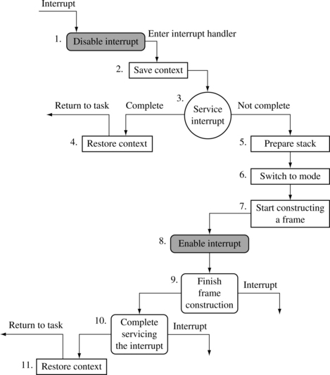
Figure 9.8 shows the various stages that occur when an interrupt is raised in a system that has implemented a simple nonnested interrupt handler:
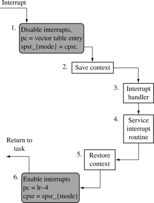
1. Disable interrupt/s—When the IRQ exception is raised, the ARM processor will disable further IRQ exceptions from occurring. The processor mode is set to the appropriate interrupt request mode, and the previous cpsr is copied into the newly available spsr_{interrupt request mode}. The processor will then set the pc to point to the correct entry in the vector table and execute the instruction. This instruction will alter the pc to point to the specific interrupt handler.
2. Save context—On entry the handler code saves a subset of the current processor mode nonbanked registers.
3. Interrupt handler—The handler then identifies the external interrupt source and executes the appropriate interrupt service routine (ISR).
4. Interrupt service routine—The ISR services the external interrupt source and resets the interrupt.
5. Restore context—The ISR returns back to the interrupt handler, which restores the context.
6. Enable interrupts—Finally, to return from the interrupt handler, the spsr_{interrupt request mode} is restored back into the cpsr. The pc is then set to the next instruction after the interrupt was raised.
EXAMPLE 9.8
This IRQ handler example assumes that the IRQ stack has been correctly set up by the initialization code.
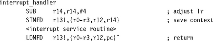
The first instruction sets the link register r14_irq to return back to the correct location in the interrupted task or process. As described in Section 9.1.4, due to the pipeline, on entry to an IRQ handler the link register points four bytes beyond the return address, so the handler must subtract four from the link register to account for this discrepancy. The link register is stored on the stack. To return to the interrupted task, the link register contents are restored from the stack and moved into the pc.
Notice registers r0 to r3 and register r12 are also preserved because of the ATPCS. This allows an ATPCS-compliant subroutine to be called within the handler.
The STMFD instruction saves the context by placing a subset of the registers onto the stack. To reduce interrupt latency we save a minimum number of registers because the time taken to execute an STMFD or LDMFD instruction is proportional to the number of registers being transferred. The registers are saved to the stack pointed to by the register r13_{interrupt request mode}.
If you are using a high-level language within your system it is important to understand the compiler’s procedure calling convention because it will influence both the registers saved and the order they are saved onto the stack. For instance, the ARM compilers preserves registers r4 to r11 within a subroutine call so there is no need to preserve them unless they will be used by the interrupt handler. If no C routines are called, it may not be necessary to save all of the registers. It is safe to call a C function only when the registers have been saved onto the interrupt stack.
Within a nonnested interrupt handler, it is not necessary to save the spsr because it will not be destroyed by any subsequent interrupt.
At the end of the handler the LDMFD instruction will restore the context and return from the interrupt handler. The ^ at the end of the LDMFD instruction means that the cpsr will be restored from the spsr, which is only valid if the pc is loaded at the same time. If the pc is not loaded, then ^ will restore the user bank registers.
In this handler all processing is handled within the interrupt handler, which returns directly to the application.
Once the interrupt handler has been entered and the context has been saved, the handler must determine the interrupt source. The following code shows a simple example of how to determine the interrupt source. IRQStatus is the address of the interrupt status register. If the interrupt source is not determined, then control can pass to another handler. In this example we pass control to the debug monitor. Alternatively we could just ignore the interrupt.
![]()
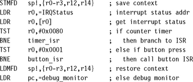
In the preceding code there are two ISRs: timer_isr and button_isr. They are mapped to specific bits in the IRQStatus register, 0x0080 and 0x0001, respectively.
SUMMARY: Simple Nonnested Interrupt Handler
![]() Handles and services individual interrupts sequentially.
Handles and services individual interrupts sequentially.
![]() High interrupt latency; cannot handle further interrupts occurring while an interrupt is being serviced.
High interrupt latency; cannot handle further interrupts occurring while an interrupt is being serviced.
![]() Advantages: relatively easy to implement and debug.
Advantages: relatively easy to implement and debug.
![]() Disadvantage: cannot be used to handle complex embedded systems with multiple priority interrupts.
Disadvantage: cannot be used to handle complex embedded systems with multiple priority interrupts.
9.3.2 NESTED INTERRUPT HANDLER
A nested interrupt handler allows for another interrupt to occur within the currently called handler. This is achieved by reenabling the interrupts before the handler has fully serviced the current interrupt.
For a real-time system this feature increases the complexity of the system but also improves its performance. The additional complexity introduces the possibility of subtle timing issues that can cause a system failure, and these subtle problems can be extremely difficult to resolve. A nested interrupt method is designed carefully so as to avoid these types of problems. This is achieved by protecting the context restoration from interruption, so that the next interrupt will not fill the stack (cause stack overflow) or corrupt any of the registers.
The first goal of any nested interrupt handler is to respond to interrupts quickly so the handler neither waits for asynchronous exceptions, nor forces them to wait for the handler. The second goal is that execution of regular synchronous code is not delayed while servicing the various interrupts.
The increase in complexity means that the designers have to balance efficiency with safety, by using a defensive coding style that assumes problems will occur. The handler has to check the stack and protect against register corruption where possible.
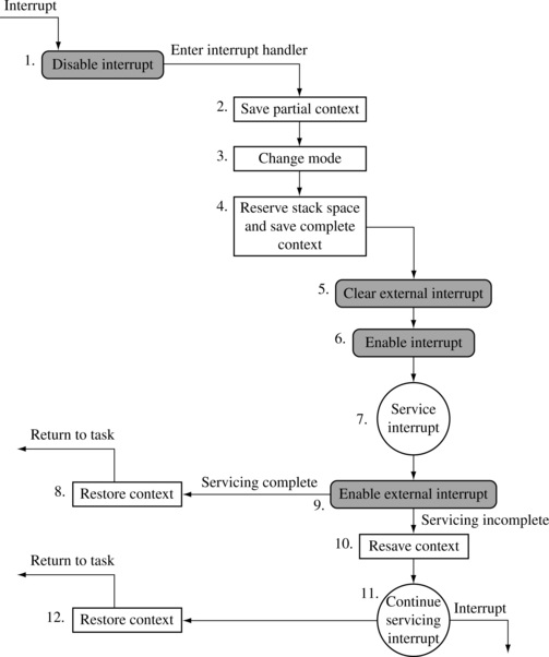
Figure 9.9 shows a nested interrupt handler. As can been seen from the diagram, the handler is quite a bit more complicated than the simple nonnested interrupt handler described in Section 9.3.1.
The nested interrupt handler entry code is identical to the simple nonnested interrupt handler, except that on exit, the handler tests a flag that is updated by the ISR. The flag indicates whether further processing is required. If further processing is not required, then the interrupt service routine is complete and the handler can exit. If further processing is required, the handler may take several actions: reenabling interrupts and/or performing a context switch.
Reenabling interrupts involves switching out of IRQ mode to either SVC or system mode. Interrupts cannot simply be reenabled when in IRQ mode because this would lead to possible link register r14_irq corruption, especially if an interrupt occurred after the execution of a BL instruction. This problem will be discussed in more detail in Section 9.3.3.
Performing a context switch involves flattening (emptying) the IRQ stack because the handler does not perform a context switch while there is data on the IRQ stack. All registers saved on the IRQ stack must be transferred to the task’s stack, typically on the SVC stack. The remaining registers must then be saved on the task stack. They are transferred to a reserved block of memory on the stack called a stack frame.
EXAMPLE 9.9
This nested interrupt handler example is based on the flow diagram in Figure 9.9. The rest of this section will walk through the handler and describe in detail the various stages.
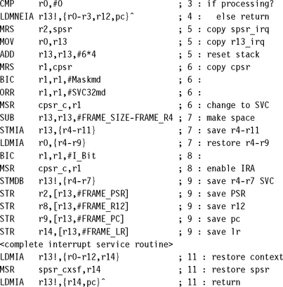
This example uses a stack frame structure. All registers are saved onto the frame except for the stack register r13. The order of the registers is unimportant except that FRAME_LR and FRAME_PC should be the last two registers in the frame because we will return with a single instruction:
![]()
There may be other registers that are required to be saved onto the stack frame, depending upon the operating system or application being used. For example:
![]() Registers r13_usr and r14_usr are saved when there is a requirement by the operating system to support both user and SVC modes.
Registers r13_usr and r14_usr are saved when there is a requirement by the operating system to support both user and SVC modes.
![]() Floating-point registers are saved when the system uses hardware floating point.
Floating-point registers are saved when the system uses hardware floating point.
There are a number of defines declared in this example. These defines map various cpsr/spsr changes to a particular label (for example, the I_Bit).
A set of defines is also declared that maps the various frame register references with frame pointer offsets. This is useful when the interrupts are reenabled and registers have to be stored into the stack frame. In this example we store the stack frame on the SVC stack.
The entry point for this example handler uses the same code as for the simple nonnested interrupt handler. The link register r14 is first modified so that it points to the correct return address, and then the context plus the link register r14 are saved onto the IRQ stack.
An interrupt service routine then services the interrupt. When servicing is complete or partially complete, control is passed back to the handler. The handler then calls a function called read_RescheduleFlag, which determines whether further processing is required. It returns a nonzero value in register r0 if no further processing is required; otherwise it returns a zero. Note we have not included the source for read_RescheduleFlag because it is implementation specific.
The return flag in register r0 is then tested. If the register is not equal to zero, the handler restores context and returns control back to the suspended task.
Register r0 is set to zero, indicating that further processing is required. The first operation is to save the spsr, so a copy of the spsr_irq is moved into register r2. The spsr can then be stored in the stack frame by the handler later on in the code.
The IRQ stack address pointed to by register r13_irq is copied into register r0 for later use. The next step is to flatten (empty) the IRQ stack. This is done by adding 6 * 4 bytes to the top of the stack because the stack grows downwards and an ADD instruction can be used to set the stack.
The handler does not need to worry about the data on the IRQ stack being corrupted by another nested interrupt because interrupts are still disabled and the handler will not reenable the interrupts until the data on the IRQ stack has been recovered.
The handler then switches to SVC mode; interrupts are still disabled. The cpsr is copied into register r1 and modified to set the processor mode to SVC. Register r1 is then written back into the cpsr, and the current mode changes to SVC mode. A copy of the new cpsr is left in register r1 for later use.
The next stage is to create a stack frame by extending the stack by the stack frame size. Registers r4 to r11 can be saved onto the stack frame, which will free up enough registers to allow us to recover the remaining registers from the IRQ stack still pointed to by register r0.
At this stage the stack frame will contain the information shown in Table 9.7. The only registers that are not in the frame are the registers that are stored upon entry to the IRQ handler.
Table 9.7
| Label | Offset | Register |
| FRAME_R0 | +0 | — |
| FRAME_R1 | +4 | — |
| FRAME_R2 | +8 | — |
| FRAME_R3 | +12 | — |
| FRAME_R4 | +16 | r4 |
| FRAME_R5 | +20 | r5 |
| FRAME_R6 | +24 | r6 |
| FRAME_R7 | +28 | r7 |
| FRAME_R8 | +32 | r8 |
| FRAME_R9 | +36 | r9 |
| FRAME_R10 | +40 | r10 |
| FRAME_R11 | +44 | r11 |
| FRAME_R12 | +48 | — |
| FRAME_PSR | +52 | — |
| FRAME_LR | +56 | — |
| FRAME_PC | +60 | — |
Table 9.8 shows the registers in SVC mode that correspond to the existing IRQ registers. The handler can now retrieve all the data from the IRQ stack, and it is safe to reenable interrupts.
Table 9.8
Data retrieved from the IRQ stack.
| Registers (SVC) | Retrieved IRQ registers |
| r4 | r0 |
| r5 | r1 |
| r6 | r2 |
| r7 | r3 |
| r8 | r12 |
| r9 | r14 (return address) |
IRQ exceptions are reenabled, and the handler has saved all the important registers. The handler can now complete the stack frame. Table 9.9 shows a completed stack frame that can be used either for a context switch or to handle a nested interrupt.
Table 9.9
| Label | Offset | Register |
| FRAME_R0 | +0 | r0 |
| FRAME_R1 | +4 | r1 |
| FRAME_R2 | +8 | r2 |
| FRAME_R3 | +12 | r3 |
| FRAME_R4 | +16 | r4 |
| FRAME_R5 | +20 | r5 |
| FRAME_R6 | +24 | r6 |
| FRAME_R7 | +28 | r7 |
| FRAME_R8 | +32 | r8 |
| FRAME_R9 | +36 | r9 |
| FRAME_R10 | +40 | r10 |
| FRAME_R11 | +44 | r11 |
| FRAME_R12 | +48 | r12 |
| FRAME_PSR | +52 | spsr_irq |
| FRAME_LR | +56 | r14 |
| FRAME_PC | +60 | r14_irq |
At this stage the remainder of the interrupt servicing may be handled. A context switch may be performed by saving the current value of register r13 in the current task’s control block and loading a new value for register r13 from the new task’s control block.
It is now possible to return to the interrupted task/handler, or to another task if a context switch occurred.
SUMMARY: Nested Interrupt Handler
![]() Handles multiple interrupts without a priority assignment.
Handles multiple interrupts without a priority assignment.
![]() Medium to high interrupt latency.
Medium to high interrupt latency.
![]() Advantage—can enable interrupts before the servicing of an individual interrupt is complete reducing interrupt latency.
Advantage—can enable interrupts before the servicing of an individual interrupt is complete reducing interrupt latency.
![]() Disadvantage—does not handle prioritization of interrupts, so lower priority interrupts can block higher priority interrupts.
Disadvantage—does not handle prioritization of interrupts, so lower priority interrupts can block higher priority interrupts.
9.3.3 REENTRANT INTERRUPT HANDLER
A reentrant interrupt handler is a method of handling multiple interrupts where interrupts are filtered by priority, which is important if there is a requirement that interrupts with higher priority have a lower latency. This type of filtering cannot be achieved using the conventional nested interrupt handler.
The basic difference between a reentrant interrupt handler and a nested interrupt handler is that the interrupts are reenabled early on in the reentrant interrupt handler, which can reduce interrupt latency. There are a number of issues relating to reenabling interrupts early, which will be described in more detail later on in this section.
All interrupts in a reentrant interrupt handler must be serviced in SVC, system, undefined instruction, or abort mode on the ARM processor.
If interrupts are reenabled in an interrupt mode and the interrupt routine performs a BL subroutine call instruction, the subroutine return address will be set in the register r14_irq. This address would be subsequently destroyed by an interrupt, which would overwrite the return address into register r14_irq. To avoid this, the interrupt routine should swap into SVC or system mode. The BL instruction can then use register r14_svc to store the subroutine return address. The interrupts must be disabled at the source by setting a bit in the interrupt controller before reenabling interrupts via the cpsr.
If interrupts are reenabled in the cpsr before processing is complete and the interrupt source is not disabled, an interrupt will be immediately regenerated, leading to an infinite interrupt sequence or race condition. Most interrupt controllers have an interrupt mask register that allows you to mask out one or more interrupts, but the remaining interrupts are still enabled.
The interrupt stack is unused since interrupts are serviced in SVC mode (for example, on the task’s stack). Instead the IRQ stack register r13 is used to point to a 12-byte structure that will be used to store some registers temporarily on interrupt entry.
It is paramount to prioritize interrupts in a reentrant interrupt handler. If the interrupts are not prioritized, the system latency degrades to that of a nested interrupt handler because lower-priority interrupts will be able to preempt the servicing of a higher-priority interrupt. This in turn leads to the locking out of higher-priority interrupts for the duration of the servicing of a lower-priority interrupt.
EXAMPLE 9.10
It is assumed that register r13_irq has been set up to point to a 12-byte data structure and does not point to a standard IRQ stack. Offsets such as IRQ_SPSR are used to point into the data structure. As with all interrupt handlers, there are some standard definitions that are required to modify the cpsr and spsr registers.
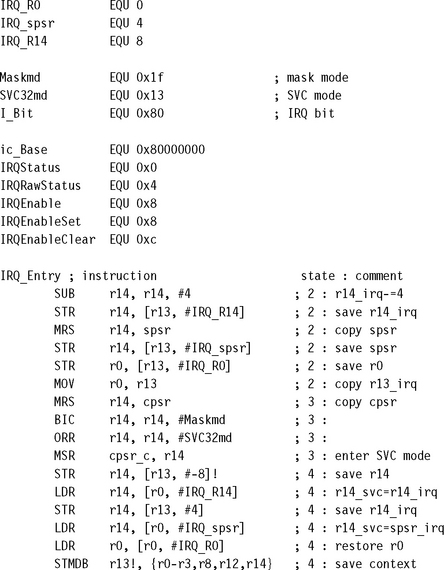
The start of the handler includes a normal interrupt entry point, with four being subtracted from the register r14_irq.
It is now important to assign values to the various fields in the data structure pointed to by register r13_irq. The registers that are recorded are r14_irq, spsr_irq, and r0. The register r0 is used to transfer a pointer to the data structure when swapping to SVC mode since register r0 will not be banked. This is why register r13_irq cannot be used for this purpose: it is not visible from SVC mode.
The pointer to the data structure is saved by copying register r13_irq into r0.
| Offset (from r13_irq) | Value |
| +0 | r0 (on entry) |
| +4 | spsr_irq |
| +8 | r14_irq |
The handler will now set the processor into SVC mode using the standard procedure of manipulating the cpsr. The link register r14 for SVC mode is saved on the SVC stack. Subtracting 8 provides room on the stack for two 32-bit words.
Register r14_irq is then recovered and stored on the SVC stack. Now both the link registers r14 for IRQ and SVC are stored on the SVC stack.
The rest of the IRQ context is recovered from the data structure passed into the SVC mode. Register r14_svc will now contain the spsr for IRQ mode.
Registers are then saved onto the SVC stack. Register r8 is used to hold the interrupt mask for the interrupts that have been disabled in the interrupt handler. They will be reenabled later.
The interrupt source(s) are then disabled. An embedded system would at this point prioritize the interrupts and disable all interrupts lower than the current priority to prevent a low-priority interrupt from locking out a high-priority interrupt. Interrupt prioritizing will be discussed later on in this chapter.
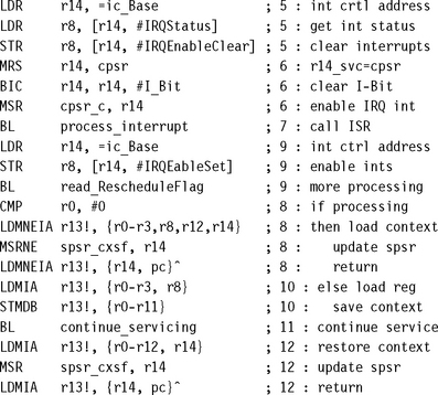
Since the interrupt source has been cleared, it is now safe to reenable IRQ exceptions. This is achieved by clearing the i bit in the cpsr. Note that the interrupt controller still has external interrupts disabled.
It is now possible to process the interrupt. The interrupt processing should not attempt to do a context switch because the external source interrupt is disabled. If during the interrupt processing a context switch is needed, it should set a flag that could be picked up later by the interrupt handler. It is now safe to reenable external interrupts.
The handler needs to check if further processing is required. If the returned value is nonzero in register r0, then no further processing is required. If zero, the handler restores the context and then returns control back to the suspended task.
A stack frame now has to be created so that the service routine can complete. This is achieved by restoring parts of the context and then storing the complete context back on to the SVC stack.
The subroutine continue_servicing, which will complete the servicing of the interrupt, is called. This routine is not provided because it is specific to an implementation.
After the interrupt routine has been serviced, control can be given back to the suspended task.
9.3.4 PRIORITIZED SIMPLE INTERRUPT HANDLER
Both the nonnested interrupt handler and the nested interrupt handler service interrupts on a first-come-first-served basis. In comparison, the prioritized interrupt handler will associate a priority level with a particular interrupt source. The priority level is used to dictate the order that the interrupts will be serviced. Thus, a higher-priority interrupt will take precedence over a lower-priority interrupt, which is a particularly desirable characteristic in many embedded systems.
Methods of handling prioritization can either be achieved in hardware or software. For hardware prioritization, the handler is simpler to design since the interrupt controller will provide the current highest-priority interrupt that requires servicing. These systems require more initialization code at startup since the interrupts and associated priority level tables have to be constructed before the system can be switched on; software prioritization, on the other hand, requires the additional assistance of an external interrupt controller. This interrupt controller has to provide a minimal set of functions that include being able to set and un-setmasks, and to read the interrupt status and source.
The rest of this section will cover a software prioritization technique chosen because it is a general method and does not rely on a specialized interrupt controller. To help describe the priority interrupt handler, we will introduce a fictional interrupt controller based upon a standard interrupt controller from ARM. The controller takes multiple interrupt sources and generates an IRQ and/or FIQ signal depending upon whether a particular interrupt source is enabled or disabled.
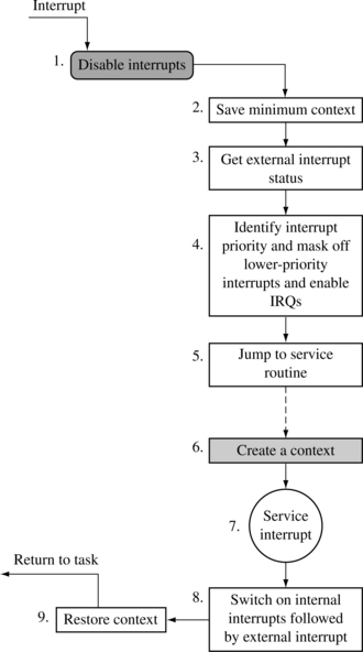
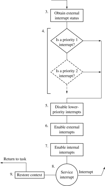
Figure 9.11 shows a flow diagram of a simple priority interrupt handler, based on a reentrant interrupt handler.
EXAMPLE 9.11
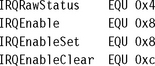
The interrupt controller has a register (IRQRawStatus) that holds the raw interrupt status—the state of the interrupt signals prior to being masked by the controller. The IRQEnable register determines which interrupts are masked from the processor. This register can only be set or cleared using IRQEnableSet and IRQEnableClear. Table 9.10 shows the interrupt controller register names, offsets from the controller’s base address, read/write operations, and a description of the registers.
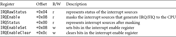
Most interrupt controllers also have a corresponding set of registers for the FIQ exceptions and even allow individual interrupt sources to be attached to a particular interrupt signal going to the core. Thus, by programming the controller, a particular interrupt source can be made to cause either an IRQ or FIQ exception.
The registers are offset from a base address in memory. Table 9.10 shows all the offsets for the various registers from interrupt controller base address ic_Base. Note that offset 0x08 is used for both IRQEnable and IRQEnableSet.
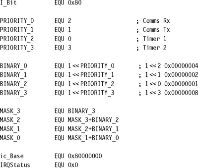
In the interrupt controller each bit is associated with a particular interrupt source (see Figure 9.12). For example, bit 2 is associated with a receive interrupt source for serial communication.
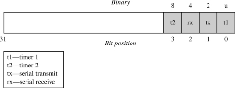
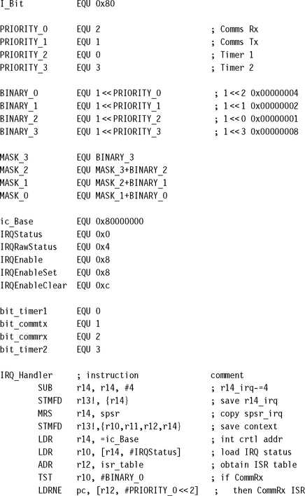
The PRIORITY_x defines the four interrupt sources, used in the example, to a corresponding set of priority levels, where PRIORITY_0 is the highest-priority interrupt and PRIORITY_3 is the lowest-priority interrupt.
The BINARY_x defines provide the bit patterns for each of the priority levels. For instance, for a PRIORITY_0 interrupt the binary pattern would be 0x00000004 (or 1 ![]() 2). For each priority level there is a corresponding mask that masks out all interrupts that are equal or lower in priority. For instance, MASK_2 will mask out interrupts from Timer2 (priority = 3) and CommRx (priority = 2).
2). For each priority level there is a corresponding mask that masks out all interrupts that are equal or lower in priority. For instance, MASK_2 will mask out interrupts from Timer2 (priority = 3) and CommRx (priority = 2).
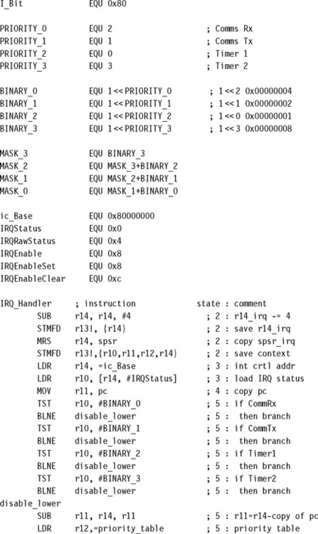
The defines for the interrupt controller registers are also listed. ic_Base is the base address, and the remaining defines (for instance, IRQStatus) are all offsets from that base address.
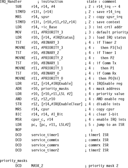
The priority interrupt handler starts with a standard entry, but at first only the IRQ link register is stored onto the IRQ stack.
Next the handler obtains the spsr and places the contents into register r14_irq and frees up a group of registers for use in processing the prioritization.
The handler needs to obtain the status of the interrupt controller. This is achieved by loading in the base address of the interrupt controller into register r14 and loading register r10 with ic_Base (register r14) offset by IRQStatus (0x00).
The handler now needs to determine the highest-priority interrupt by testing the status information. If a particular interrupt source matches a priority level, then the priority level is set in register r11. The method compares the interrupt source with all the set priority levels, starting first with the lowest priority and working to the highest priority.
After this code fragment, register r14_irq will contain the base address of the interrupt controller, and register r11 will contain the bit number of the highest-priority interrupt. It is now important to disable the lower- and equal-priority interrupts so that the higher-priority interrupts can still interrupt the handler.
Notice that this method is more deterministic since the time taken to discover the priority is always the same.
To set the interrupt mask in the controller, the handler must determine the current IRQ enable register and also obtain the start address of the priority mask table. The priority_masks are defined at the end of the handler.
Register r12 will now contain the current IRQ enable register, and register r10 will contain the start address of the priority table. To obtain the correct mask, register r11 is shifted left by two (using the barrel shifter LSL #2). This will multiply the address by four and add that to the start address of the priority table.
Register r10 contains the new mask. The next step is to clear the lower-priority interrupts using the mask, by performing a binary AND with the mask and register r12 (IRQEnable register) and then clearing the bits by storing the new mask into IRQEnableClear register. It is now safe to enable IRQ exceptions by clearing the i bit in the cpsr.
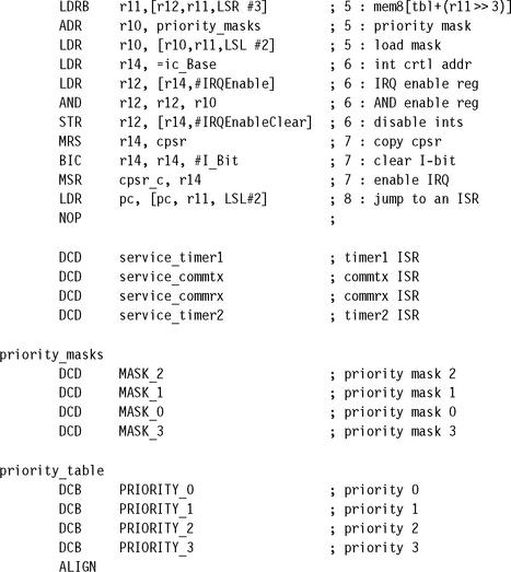
Lastly the handler needs to jump to the correct service routine, by modifying register r11 (which still contains the highest-priority interrupt) and the pc. Shifting register r11 left by two (multiplying by four) and adding it to the pc allows the handler to jump to the correct routine by loading the address of the service routine directly into the pc.
The jump table has to follow the instruction that loads the pc. There is an NOP in between the jump table and the instruction that manipulates the pc because the pc will be pointing two instructions ahead (or eight bytes). The priority mask table is in interrupt source bit order.
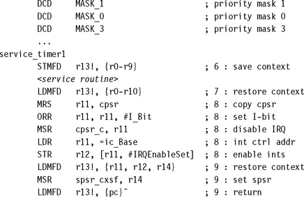
Each ISR follows the same entry style. The example given is for the timer1 interrupt service routine.
The ISR is then inserted after the header above. Once the ISR is complete, the interrupt sources must be reset and control passed back to the interrupted task.
The handler must disable the IRQs before the interrupts can be switched back on. The external interrupts can now be restored to their original value, which is possible because the service routine did not modify register r12 and so it still contains the original value.
To return back to the interrupted task, context is restored and the original spsr is copied back into the spsr_irq.
SUMMARY: Prioritized Simple Interrupt Handler
![]() Handles prioritized interrupts.
Handles prioritized interrupts.
![]() Advantage: deterministic interrupt latency since the priority level is identified first and then the service is called after the lower-priority interrupts are masked.
Advantage: deterministic interrupt latency since the priority level is identified first and then the service is called after the lower-priority interrupts are masked.
![]() Disadvantage: the time taken to get to a low-priority service routine is the same as for a high-priority routine.
Disadvantage: the time taken to get to a low-priority service routine is the same as for a high-priority routine.
9.3.5 PRIORITIZED STANDARD INTERRUPT HANDLER
Following on from the prioritized simple interrupt handler, the next handler adds an additional level of complexity. The prioritized simple interrupt handler tested all the interrupts to establish the highest priority—an inefficient method of establishing the priority level but it does have the advantage of being deterministic since each interrupt priority will take the same length of time to be identified.
An alternative approach is to jump early when the highest-priority interrupt has been identified (see Figure 9.13), by setting the pc and jumping immediately once the priority level has been established. This means that the identification section of the code for the prioritized standard interrupt handler is more involved than for the prioritized simple interrupt handler. The identification section will determine the priority level and jump immediately to a routine that will handle the masking of the lower-priority interrupts and then jump again via a jump table to the appropriate ISR.
EXAMPLE 9.12
A prioritized standard interrupt handler starts the same as a prioritized simple interrupt handler but intercepts the interrupts with a higher-priority earlier. Register r14 is assigned to point to the base of the interrupt controller and load register r10 with the interrupt controller status register. To allow the handler to be relocatable, the current address pointed to by the pc is recorded into register r11.
The interrupt source can now be tested by comparing the highest to the lowest priority. The first priority level that matches the interrupt source determines the priority level of the incoming interrupt because each interrupt has a preset priority level. Once a match is achieved, then the handler can branch to the routine that masks off the lower-priority interrupts.
To disable the equal- or lower-priority interrupts, the handler enters a routine that first calculates the priority level using the base address in register r11 and link register r14.
Following the SUB instruction register r11 will now contain the value 4, 12, 20, or 28. These values correspond to the priority level of the interrupt multiplied by eight plus four. Register r11 is then divided by eight and added to the address of the priority_table. Following the LDRB register r11 will equal one of the priority interrupt numbers (0, 1, 2, or 3).
The priority mask can now be determined, using the technique of shifting left by two and adding that to the register r10, which contains the address of the priority_mask.
The base address for the interrupt controller is copied into register r14_irq and is used to obtain the IRQEnable register in the controller and place it into register r12.
Register r10 contains the new mask. The next step is to clear the lower-priority interrupts using this mask by performing a binary AND with the mask and r12 (IRQEnable register) and storing the result into the IRQEnableClear register. It is now safe to enable IRQ exceptions by clearing the i bit in the cpsr.
Lastly the handler needs to jump to the correct service routine, by modifying r11 (which still contains the highest-priority interrupt) and the pc. Shifting register r11 left by two (multiplying r11 by four) and adding it to the pc allows the handler to jump to the correct routine by loading the address of the service routine directly into the pc. The jump table must follow the instruction that loads the pc. There is an NOP between the jump table and the LDR instruction that modifies the pc because the pc is pointing two instructions ahead (or eight bytes).
Note that the priority mask table is in interrupt bit order, and the priority table is in priority order.
SUMMARY: Prioritized Standard Interrupt Handler
![]() Handles higher-priority interrupts in a shorter time than lower-priority interrupts.
Handles higher-priority interrupts in a shorter time than lower-priority interrupts.
![]() Advantage: higher-priority interrupts treated with greater urgency with no duplication of code to set external interrupt masks.
Advantage: higher-priority interrupts treated with greater urgency with no duplication of code to set external interrupt masks.
![]() Disadvantage: there is a time penalty since this handler requires two jumps, resulting in the pipeline being flushed each time a jump occurs.
Disadvantage: there is a time penalty since this handler requires two jumps, resulting in the pipeline being flushed each time a jump occurs.
9.3.6 PRIORITIZED DIRECT INTERRUPT HANDLER
One difference between the prioritized direct interrupt handler and the prioritized standard interrupt handler is that some of the processing is moved out of the handler into the individual ISRs. The moved code masks out the lower-priority interrupts. Each ISR will have to mask out the lower-priority interrupts for the particular priority level, which can be a fixed number since the priority level has already been previously determined.
The second difference is that the prioritized direct interrupt handler jumps directly to the appropriate ISR. Each ISR is responsible for disabling the lower-priority interrupts before modifying the cpsr to reenable interrupts. This type of handler is relatively simple since the masking is done by the individual ISR, but there is a small amount of code duplication since each interrupt service routine is effectively carrying out the same task.
EXAMPLE 9.13
The bit_x defines associate an interrupt source with a bit position within the interrupt controller, which will be used to help mask the lower-priority interrupts within an ISR.
Once the context is saved, the base address of the ISR table has to be loaded into register r12. This register is used to jump to the correct ISR once the priority has been established for the interrupt source.
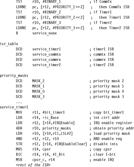
The priority interrupt is established by checking the highest-priority interrupt first and then working down to the lowest. Once a priority interrupt is identified, the pc is then loaded with the address of the appropriate ISR. The indirect address is stored at the address of the isr_table plus the priority level shifted two bits to the left (multiplied by four). Alternatively you could use a conditional branch BNE.
The ISR jump table isr_table is ordered with the highest-priority interrupt at the beginning of the table.
The service_timer1 entry shows an example of an ISR used in a priority direct interrupt handler. Each ISR is unique and depends upon the particular interrupt source.
A copy of the base address for the interrupt controller is placed into register r14_irq. This address plus an offset is used to copy the IRQEnable register into register r12.
The address of the priority mask table has to be copied into register r10 so it can be used to calculate the address of the actual mask. Register r11 is shifted left two positions, which gives an offset of 0, 4, 8, or 12. The offset plus the address of the priority mask table address is used to load the mask into register r10. The priority mask table is the same as for the priority interrupt handler in the previous section.
Register r10 will contain the ISR mask, and register r12 will contain the current mask. A binary AND is used to merge the two masks. Then the new mask is used to configure the interrupt controller using the IRQEnableClear register. It is now safe to enable IRQ exceptions by clearing the i bit in the cpsr.
The handler can continue servicing the current interrupt unless an interrupt with a higher priority occurs, in which case that interrupt will take precedence over the current interrupt.
SUMMARY: Prioritized Direct Interrupt Handler
![]() Handles higher-priority interrupts in a shorter time. Goes directly to the specific ISR.
Handles higher-priority interrupts in a shorter time. Goes directly to the specific ISR.
![]() Advantage: uses a single jump and saves valuable cycles to go to the ISR.
Advantage: uses a single jump and saves valuable cycles to go to the ISR.
![]() Disadvantage: each ISR has a mechanism to set the external interrupt mask to stop lower-priority interrupts from halting the current ISR, which adds extra code to each ISR.
Disadvantage: each ISR has a mechanism to set the external interrupt mask to stop lower-priority interrupts from halting the current ISR, which adds extra code to each ISR.
9.3.7 PRIORITIZED GROUPED INTERRUPT HANDLER
Lastly, the prioritized grouped interrupt handler differs from the other prioritized interrupt handlers since it is designed to handle a large set of interrupts. This is achieved by grouping interrupts together and forming a subset, which can then be given a priority level.
The designer of an embedded system must identify each subset of interrupt sources and assign a group priority level to that subset. It is important to be careful when selecting the subsets of interrupt sources since the groups can determine the characteristics of the system. Grouping the interrupt sources together tends to reduce the complexity of the handler since it is not necessary to scan through every interrupt to determine the priority level. If a prioritized grouped interrupt handler is well designed, it will dramatically improve overall system response times.
EXAMPLE 9.14
This handler has been designed to have two priority groups. Timer sources are grouped into group 0, and communication sources are grouped into group 1 (see Table 9.11.) Group 0 interrupts are given a higher priority than group 1 interrupts.
![]()
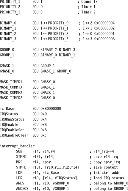
The GROUP_x defines assign the various interrupt sources to their specific priority level by using a binary OR operation on the binary patterns. The GMASK_x defines assign the masks for the grouped interrupts. The MASK_x defines connect each GMASK_x to a specific interrupt source, which can then be used in the priority mask table.
After the context has been saved the interrupt handler loads the IRQ status register using an offset from the interrupt controller base address.
The handler then identifies the group to which the interrupt source belongs by using the binary AND operation on the source. The letter S postfixed to the instructions means update condition flags in the cpsr.
Register r11 will now contain the highest-priority group 0 or 1. The handler now masks out the other interrupt sources by applying a binary AND operation with 0xf.
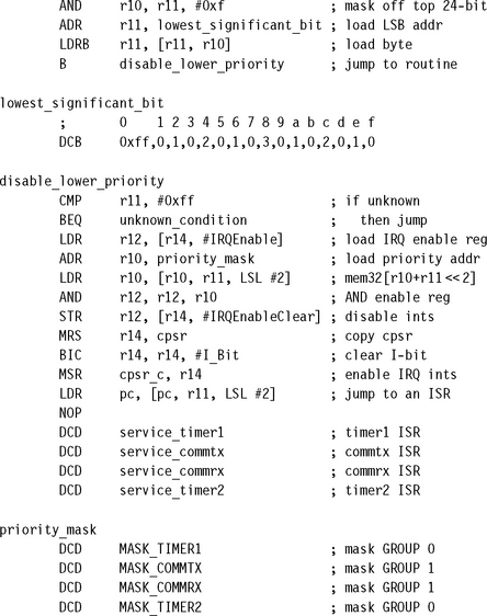
The address of the lowest significant bit table is then loaded into register r11. A byte is loaded from the start of the table using the value in register r10 (0, 1, 2, or 3, see Table 9.12). Once the lowest significant bit position is loaded into register r11, the handler branches to a routine.
Table 9.12
| Binary pattern | Value |
| 0000 | unknown |
| 0001 | 0 |
| 0010 | 1 |
| 0011 | 0 |
| 0100 | 2 |
| 0101 | 0 |
| 0110 | 1 |
| 0111 | 0 |
| 1000 | 3 |
| 1001 | 0 |
| 1010 | 1 |
| 1011 | 0 |
| 1100 | 2 |
| 1101 | 0 |
| 1110 | 1 |
| 1111 | 0 |
The disable_lower_priority interrupt routine first checks for a spurious (no longer present) interrupt. If the interrupt is spurious, then the unknown_condition routine is called. The handler then loads the IRQEnable register and places the result in register r12.
The priority mask is found by loading in the address of the priority mask table and then shifting the data in register r11 left by two. The result, 0, 4, 8, or 12, is added to the priority mask address. Register r10 then contains a mask to disable the lower-priority group interrupts from being raised.
The next step is to clear the lower-priority interrupts using the mask by performing a binary AND with the mask in registers r10 and r12 (IRQEnable register) and then clearing the bits by saving the result into the IRQEnableClear register. At this point it is now safe to enable IRQ exceptions by clearing the i bit in the cpsr.
Lastly the handler jumps to the correct interrupt service routine by modifying register r11 (which still contains the highest-priority interrupt) and the pc. By shifting register r11 left by two and adding the result to the pc the address of the ISR is determined. This address is then loaded directly into the pc. Note that the jump table must follow the LDR instruction. The NOP is present due to the ARM pipeline.
SUMMARY: Prioritized Grouped Interrupt Handler
![]() Mechanism for handling interrupts that are grouped into different priority levels.
Mechanism for handling interrupts that are grouped into different priority levels.
![]() Advantage: useful when the embedded system has to handle a large number of interrupts, and also reduces the response time since the determining of the priority level is shorter.
Advantage: useful when the embedded system has to handle a large number of interrupts, and also reduces the response time since the determining of the priority level is shorter.
![]() Disadvantage: determining how the interrupts are grouped together.
Disadvantage: determining how the interrupts are grouped together.
9.3.8 VIC PL190 BASED INTERRUPT SERVICE ROUTINE
To take advantage of the vector interrupt controller, the IRQ vector entry has to be modified.
![]()
This instruction loads an ISR address from the memory mapped location 0xffffff030 into the pc which bypasses any software interrupt handler since the interrupt source can be obtained directly from the hardware. It also reduces interrupt latency since there is only a single jump to a specific ISR.
Here is an example of VIC service routine:
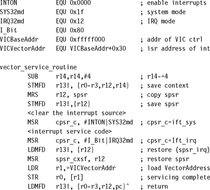
This routine saves the context and s psr_irq before clearing the interrupt source. Once this is complete, the IRQ exceptions can be reenabled by clearing the i bit, and the processor mode is set to system mode. The service routine can then process the interrupt in system mode. Once complete, the IRQ exceptions are disabled by setting the i bit, and the processor mode is switched back to IRQ mode.
The spsr_irq is restored from the IRQ stack, preparing the routine to return to the interrupted task.
The service routine then writes to the VICVectorAddr register in the controller. Writing to this address indicates to the priority hardware that the interrupt has been serviced.
Note that since the VIC is basically a hardware interrupt handler, the array of ISR addresses must be preprogrammed into the VIC before it is activated.
9.4 SUMMARY
An exception changes the normal sequential execution of instructions. There are seven exceptions: Data Abort, Fast Interrupt Request, Interrupt Request, Prefetch Abort, Software Interrupt, Reset, and Undefined Instruction. Each exception has an associated ARM processor mode. When an exception is raised, the processor goes into a specific mode and branches to an entry in the vector table. Each exception also has a priority level.
Interrupts are a special type of exception that are caused by an external peripheral. The IRQ exception is used for general operating system activities. The FIQ exception is normally reserved for a single interrupt source. Interrupt latency is the interval of time from an external interrupt request signal being raised to the first fetch of an instruction of a specific interrupt service routine (ISR).
We covered eight interrupt handling schemes, from a very simple nonnested interrupt handler that handles and services individual interrupts, to an advanced prioritized grouped interrupt handler that handles interrupts that are grouped into different priority levels.