
6
Implementing and Managing Azure Network Infrastructure
This chapter covers AZ-800 Administering Windows Server Hybrid Core Infrastructure: Implement and manage Azure network infrastructure.
In the previous chapter, we added skills to understand the concepts of on-premises network infrastructure and services. We will start this chapter with an understanding of network services concepts in Azure. We will then look at each network service in more detail and conclude with a hands-on exercise to develop your skills further.
The following topics are included in this chapter:
- Introduction to Azure network services
- Implementing virtual networks (VNets) in Azure
- Implementing network connectivity in Azure
- Implementing network protection in Azure
- Implementing name resolution in Azure
- Hands-on exercises
In addition to the topics listed in this chapter, this chapter’s goal is to take your knowledge beyond the exam objectives to prepare you for a real-world, day-to-day hybrid environment-focused role.
Introduction to Azure network services
This section introduces the functionality of the network services available in Azure, why each service is required, and how it may be used. Each network service capability will be covered in more detail in this chapter.
The following list outlines the available network services capabilities:
- Communication between resources in Azure: VNets provide the communication paths for network traffic between Azure resources such as virtual machines (VMs), load balancers, firewalls, and so on. Communication between VNets in the same region or another region is handled by VNet peering using the Microsoft backbone. Service endpoints and private endpoints are available for connecting platform-as-a-service (PaaS) resources such as database and storage services to VNets.
- Communication with resources on-premises: Virtual private networks (VPNs) as well as Azure Relay, Azure Network Adapter, Azure Virtual WAN, and ExpressRoute can provide hybrid connectivity scenarios, such as extending on-premises networks into Azure.
- Communication with the internet: VMs can communicate on the internet for both incoming and outgoing traffic and can be provided with network and application and protection services as well as network address translation (NAT) and routing.
- Segmentation of address spaces: VNets can be segmented with subnets like on-premises networks to optimize the address space(s) defined in the VNets. Traffic filtering and routing can also be applied at the subnet level. The address spaces will typically be RFC 1918 private ranges, but public IP prefixes are also supported. For security reasons, VM resources should have IPs assigned from the private IP address space with public IPs associated with load balancers, firewalls, and so on. In a specific scenario, the Extended Network for Azure provides a subnet extension, meaning an on-premises subnet can be stretched into Azure. Azure resources can also communicate with resources on the same local on-premises network.
- Routing of network traffic: A VNet uses default system routes to determine traffic paths. User-Defined Routes (UDRs) are much like static routes in on-premises networking; these allow the default system routes to be overridden with a more preferred and specific next-hop traffic path. This next hop could be a Network Virtual Appliance (NVA) such as a firewall.
- Filtering of network traffic: There is no traffic filtering in a VNet by default. A network security group (NSG) is a built-in Azure packet filter service for network protection. Network traffic inbound and outbound of a VNet can be controlled through a set of allow and deny rules. Filtering traffic can be applied based on factors such as source, destination, port, protocol, and so on. The Azure Firewall service can, in addition, provide Layer 4 and Layer 7 protection services.
- Encryption of network traffic: An Azure VPN Gateway can encrypt communication between Azure and remote networks such as on-premises locations.
- Speed of network traffic: Due to the inherent nature of the internet, if a low-latency connection is required between Azure and on-premises locations, then Azure ExpressRoute can be used. This provides a managed private network connection that bypasses the internet for traffic.
- Name resolution: Name resolution in Azure can be provided by a traditional Windows Server DNS running on a VM or provided by Azure DNS, which is a managed service that is fully VNet-integrated to provide both public and private zones.
In this section, we introduced some of the Azure network services. In the following sections of this chapter, we will cover each of these areas. The first topic we will look at in the next section is VNets.
Implementing VNets in Azure
This section will look at implementing and managing Azure VNets. We will cover VNet peering, VNet routing, implementing IP addressing, and the Extended Network for Azure.
The first skills area we will look at in this section is VNets in Azure and how they work.
Azure VNets
An Azure VNet is a software-defined representation of a Local Area Network (LAN) that you would have on-premises.
A VNet provides communication paths between resources through network interfaces. When resources in on-premises locations communicate with resources in Azure, this can be referred to as hybrid connectivity or cross-premises connectivity.
A VNet provides a private and isolated single-tenant network for your resources to communicate in. You can define private IP address spaces and segment them into subnets as you would for on-premises.
Each connected device on the VNet will be assigned a unique IP through the Azure Dynamic Host Configuration Protocol (DHCP) service. VMs are recommended to be assigned private IPs.
Public IPs can also be assigned to resources, although they are recommended for association with firewalls, load balancers, and so on for security reasons.
A VNet allows for network interfaces to be created that belong to a subnet as part of the segmentation of an IP address space associated with the VNet. These network interfaces are assigned an IP address in the range from that subnet by the Microsoft DHCP service; you cannot bring your own DHCP servers.
For a VM to communicate on the network, it must have one or more network interfaces associated with it. You would assign network interfaces according to the subnets you wish to send or receive traffic. A VM can have a network interface assigned from one or more subnets, with the maximum number of network interfaces supported by the VM type. The network interface is always allocated to the VM, even in the shutdown state. However, when the VM is deleted, the network interface remains a standalone resource but can be deleted as required.
A VNet in Azure exists in the boundary of an Azure region and is a communication boundary for network traffic within that region.
A VNet can span across a data center zone but cannot span a region. You can connect VNets in different regions and allow the traffic to span as though it were one network.
The default traffic behavior is that a VNet allows all resources within that VNet to communicate with each other but not with resources in another VNet without additional configuration steps.
A VNet can connect to on-premises locations for hybrid connectivity through a VPN gateway. Only one VPN gateway can be created for a VNet and can be created as a VPN type or an ExpressRoute type. Both types can exist on the same gateway if enough IP addressing is available to assign in address space; it is recommended to create a VPN subnet of /27 as a minimum.
VNet peering
VMs in one or more VNets can communicate with each other through VNet peering.
Unlike a VPN gateway where the communication traffic must route over the internet, VNet peering allows communication to flow as though they are the same logical network, and traffic passes over Microsoft’s backbone and bypasses the internet. This is important in terms of speed, reliability, and security. VNet peering is available as regional VNet peering, which connects VNets in the same region, and global VNet peering, which connects VNets in different regions.
This is represented in the following diagram:
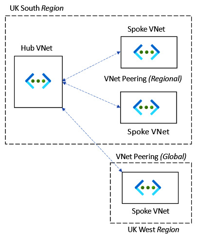
Figure 6.1 – VNet peering
In this section, we looked at what an Azure VNet was. In this next section, we will look at IP addressing for VMs.
How to implement IP addressing
When a VNet is created, you define one or more IP address spaces. This can then be further broken down into subnets to meet your requirements. Each resource can be assigned an IP address from the subnet so that other resources can communicate with it on the network.
This is represented in the following diagram:
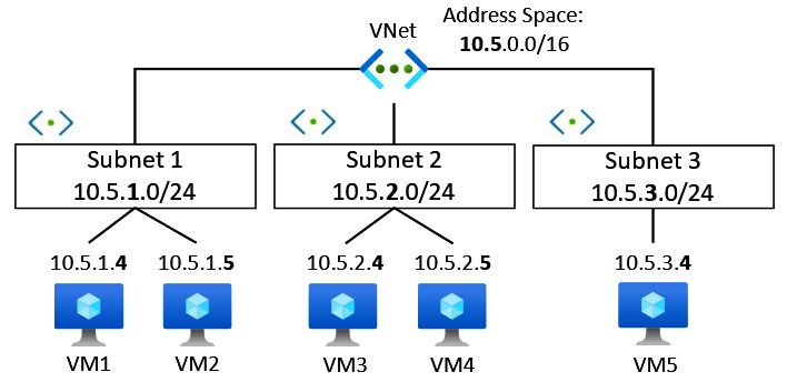
Figure 6.2 – IP address subnetting
The preceding diagram represents a VNet with an address space defined using the classless inter-domain routing (CIDR) format of 10.5.0.0/16. Subnetting has been used to further segment into smaller subnets that use a /24 notation, and each resource is allocated an IP from this range. This approach allows us to optimize the IP address allocation from the defined address /16 space. A VNet can have more than one IP address space assigned, which can be a public IP address prefix but is more commonly a private address range.
The following are the recommended private non-routable (RFC 1918) address ranges:
- 192.168.0.0 to 192.168.255.255 (192.168/16 prefix)
- 172.16.0.0 to 172.31.255.255 (172.16/12 prefix)
- 10.0.0 to 10.255.255.255 (10/8 prefix)
The private IP addresses are static or dynamically assigned to the network interfaces and can be changed between the two at any time. Typically, static IP addresses will be used, especially in the case of VMs that will perform roles such as domain controllers, DNS servers, or NVAs, where it is critical that the IPs remain assigned and not change. Private IPs (static and dynamic) can also be assigned to resources such as load balancers and network interfaces of storage services, for example, that use private endpoints.
When planning IP addressing in Azure, it is essential to note that Azure reserves five IP addresses for its own use in each subnet range, which cannot be allocated to any resources. These five reserved IP addresses are the first four IP addresses and the last IP address in a range, with the IP address ranges starting at 0, not 1.
The reserved five IP addresses are utilized as follows:
- x.x.x.0: This first IP address is used for the network address
- x.x.x.1: This second IP address is used for the default gateway
- x.x.x.2: This third address is used for Azure DNS
- x.x.x.3: This fourth IP address is used for Azure DNS
- x.x.x.255: This fifth IP address is used for the broadcast address
You will notice from the preceding list that the first IP assigned to a created VM in the subnet will be the .4 address.
Public IP addressing prefixes can be added to Azure VNets and can be assigned to resources such as network interfaces, VPN gateways, NVAs, and internet-facing load balancers. There are basic- and standard-type stock-keeping units (SKUs).
IPv6 can also be used alongside IPv4 in the same VNet and for the same resource. When a resource such as a VM has requirements for IPv6 and IPv4 communication paths, that is known as a dual stack.
Azure Extended Network
The Extended Network for Azure capability provides a subnet extension, meaning an on-premises subnet can be stretched into Azure to meet the requirements of specific scenarios, and vice versa. Azure resources can be part of your on-premises local network, akin to making the same IP broadcast domain available in separate locations. It should be noted that this is not necessarily a good practice but may be required for a specific scenario that dictates this requirement.
This is achieved by extending the on-premises Layer 2 network with a Layer 3 overlay network using a Virtual Extensible LAN (VXLAN) solution. The advantage is that when VMs move to Azure, they can retain their existing IPs. Ordinarily, this is not possible as there cannot be overlapping IP address space between the on-premises networks and Azure.
This is represented in the following diagram:
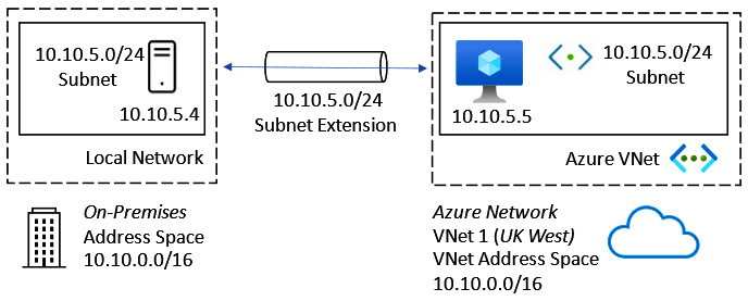
Figure 6.3 – Azure Extended Network subnet extension
This section looked at how to implement IP addressing in an Azure VNet. In the next section, we will look at implementing VNet routing.
How to implement VNet routing
As we learned earlier, an Azure VNet is a software-defined representation of on-premises networks. When a VNet is created, an RFC 1918 private address space can be configured, and subnets created for the segmented network design are required. In an earlier example, we saw a /16 address space that contained /24 subnets for IP assignment to network interfaces that could be attached to VMs to allow them to communicate within the VNet.
Azure has a set of default system routes that automatically provide the Azure built-in routing capability; this allows VMs in the same VNet to communicate with each other with no specific network configuration required. The default gateway address is pre-defined at .1 in any subnet, and the system routes determine the next hop paths. These routes cannot be edited or removed, although you can provide custom routes that allow you to override the system routes with more specific routes that take priority over the system routes. These custom routes are referred to as UDRs. UDRs are applied through a route table resource. This provides specific network packet control of where the next hop should be for any packet leaving a subnet where it is not desired to use the default .1 gateway next hops.
The next-hop type can be one of the following:
- Virtual appliance
- VNet gateway
- VNet
- Internet
Implementing UDRs in subnets is particularly beneficial when we want the next hop for traffic leaving a subnet to be filtered and inspected by an NVA such as a firewall. This allows us to control east-west traffic and provides network protection against lateral attacks.
This concept is represented in the following diagram:
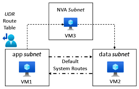
Figure 6.4 – Network routing in Azure
In the preceding diagram, we see that the default system routing shows direct communication possible between the VM1 and VM2 VMs. This allows VM2 to communicate with VM1 using the default system route.
Due to the UDR route table being associated with the app subnet, all packets leaving the app subnet will use the custom routes provided by the UDR route table.
In this case, the route table has an entry that specifies that for all traffic with a destination of the data subnet, its next hop must be VM3.
This means VM1 cannot communicate with VM2 directly, but VM1 can only communicate with VM2 via VM3, a firewall appliance VM; if VM1 were to be compromised, this approach would protect VM2 from a lateral movement attack.
We should also discuss in this section the topic of egress routing. This is where we can determine the path of traffic leaving an Azure VNet, based on cost, quality, and performance metrics.
The two options available for egress routing are set out here:
- Cold-potato routing: With this routing method, traffic remains on the global Microsoft backbone for as long as possible. The final destination gets the traffic once the Microsoft backbone has handed off to a downstream ISP edge Point of Presence (POP) to perform this last-mile traffic delivery.
- Hot-potato routing: With this routing method, the traffic leaves the Microsoft global network at the earliest opportunity and travels to its destination via many hops across the internet, hence the term hot potato, as the traffic is not held on to for long before being handed off to the next hop or hand-off for the packet.
This concept is represented in the following diagram:
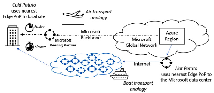
Figure 6.5 – Egress routing in Azure
The preceding diagram visualizes the cold-potato versus hot-potato egress routing methods; the benefits and disadvantages are as follows:
- Cold-potato routing is the most expensive form of egress routing but has the benefit of the lowest latency, best quality, and fastest performance. Think of this as a courier service versus a regular mail delivery service.
- Hot-potato routing is the cheapest option, but the disadvantage is that it has the slowest and least reliable delivery. Think of this as a regular mail delivery service versus a courier service.
We can also link this traffic delivery method to air transport versus ground/boat shipping.
In this section, we looked at VNet routing. The following section will look at implementing hybrid network connectivity in Azure.
Implementing network connectivity in Azure
This section will look at network connectivity in Azure between VNets as well as cross-premises/hybrid options available in Azure.
While there are many third-party vendor solutions, we will look to introduce only the first-party Microsoft services available in Azure and for the exam skills objectives.
VPNs are the first skills area we will look at in this section.
VPNs
The Microsoft VPN Gateway is a network connectivity service that provides traffic encryption through private and secure tunnels across the internet. These tunnels can connect on-premises networks to Azure VNets or connect VNets in the same region or across different regions.
When a VPN gateway is implemented, it can be created as two types:
- VPN connection type
- ExpressRoute connection
Only one VNet gateway can be created per VNet, with a high availability (HA) option; VNets can’t share a gateway.
The gateway type must be deleted and created again with the correct type to change it.
VPN connection type gateways can be created as two VPN types:
- Policy-based (static routing) VPN gateway
- Route-based (dynamic routing) VPN gateway
The VPN gateway can create Point-to-Site VPNs and Site-to-Site VPNs.
The Internet Protocol Security (IPsec) protocol Internet Key Exchange (IKE) versions 1 and 2 can be used; pre-shared keys are used for authentication.
The following connectivity types require a route-based VPN gateway:
- Point-to-Site VPN
- Inter-VNet connections
- Multi-site connections
- ExpressRoute coexistence
This section introduced the VPN Gateway service in Azure. The following sections will look at the Point-to Site and Site-to-Site VPN types.
Point-to-Site VPN
A Point-to-Site VPN type provides an encrypted connection from a single device to Azure resources by creating a secure tunnel across the internet for communication.
The protocols used for this VPN type are as follows:
- OpenVPN
- Secure Socket Tunneling Protocol (SSTP)
- IKEv2
This Point-to-Site VPN type is represented in the following diagram:
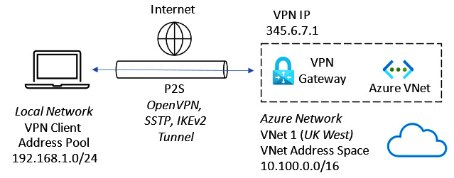
Figure 6.6 – Point-to-Site VPN
The use case for a Point-to-Site VPN is when remote workers, such as home workers or those traveling, need access to Azure resources accessible via VNets and cannot use a Site-to-Site VPN.
Site-to-Site VPN
A Site-to-Site VPN type provides an encrypted connection from on-premises locations to Azure resources by creating a secure tunnel across the internet for communication to support hybrid connectivity/cross-premises scenarios.
The Azure VPN gateway supports policy-based and route-based VPNs and the IPsec v1/v2 protocols; pre-shared keys are used for authentication.
This Site-to-Site VPN type is represented in the following diagram:
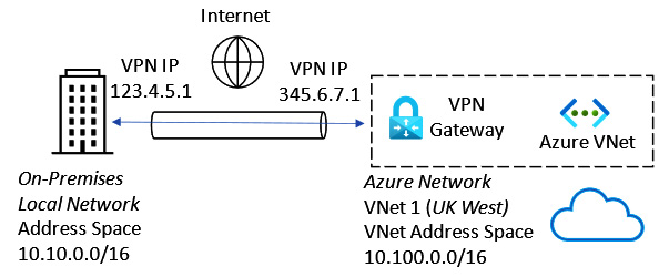
Figure 6.7 – Site-to-Site VPN
In the preceding diagram, the on-premises location must have a VPN device with a public IP address. Note that without the deployment of Azure Extended Network, the on-premises and Azure VNet address spaces cannot overlap; Layer 3 routing over the public internet is required.
A VPN gateway can also establish VPN tunnels to multiple on-premises locations using a single VNet gateway.
This multi-site VPN connection type is represented in the following diagram:
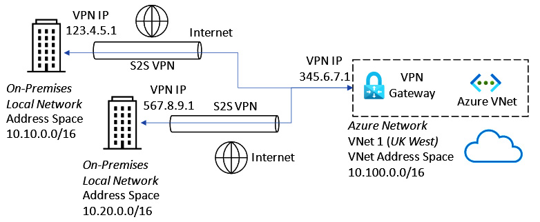
Figure 6.8 – Multi-site VPN connection
For multiple VPN connection tunnels to co-exist on a single VNET gateway, you must use a route-based VPN to support this.
VNet-to-VNet VPN
VPNs can also connect two Azure VNets to allow encrypted communications.
This VNet-to-VNet VPN type is represented in the following diagram:

Figure 6.9 – VNet-to-VNet VPN connection
To interconnect Azure VNets, we can also use the alternative method of VNet peering; however, this does not encrypt the traffic, bypasses the internet, and stays on Microsoft’s backbone.
Implementing Azure VNet gateways
As we learned earlier, a VNet gateway is an Azure resource that connects on-premises networks to Azure VNets over the internet. Secure and private tunnels are created through which encrypted traffic can be sent. This allows resources in both cloud and on-premises locations to communicate as though they were on the same local network.
A VNet gateway requires the following resources to be implemented:
- VNet: The VNet gateway resource can only be associated with one VNet; a VNet cannot have more than one VPN gateway. There should be no overlap of IP address space ranges between the Azure VNet and the on-premises networks—that is, Azure networks should be created with unique CIDR IP address space ranges.
- Gateway subnet: A dedicated subnet resource is required to be created in the VNet and must be called GatewaySubnet. The VNet address space used must have sufficient IPs available to assign. It is recommended this should be /27, /26, or larger to ensure enough IP addresses are available, especially if you wish ExpressRoute to co-exist on the same VNet gateway.
- Public IP address: This resource is used by the remote VPN device to connect to the VNet gateway.
- Local network gateway: This resource represents the remote network location; be careful of the local terminology: this means the network at the other end of the tunnel from the VNet gateway. This identifies the on-premises VPN device used to connect with the Azure VPN gateway. You specify the network ranges you will allow a connection from.
- Connection: This resource represents a logical connection between the VPN and the local network gateway.
The preceding resources and their relationships are represented in the following diagram:

Figure 6.10 – VPN gateway resources
VNet gateway is also used when implementing ExpressRoute, which we will look at in the next section.
ExpressRoute
An ExpressRoute circuit is an extension of your on-premises network into Azure without the need for VPNs or traversing the internet. It provides cross-premises/hybrid connectivity using a reliable, low-latency, fast private network, with traffic routed directly to Microsoft’s data centers, bypassing the internet. This private network is facilitated by a network carrier provider, which acts as the connectivity provider.
This is represented in the following diagram:
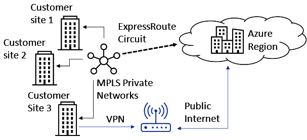
Figure 6.11 – ExpressRoute
Working with a network carrier provider, ExpressRoute can make Azure data centers appear as a site on a Multiprotocol Label Switching (MPLS) network. This provides global reach and capacity extensions of on-premises locations into Azure Data centers.
With ExpressRoute being an enterprise-grade network solution, redundancy is built in using Border Gateway Protocol (BGP) and dynamic routing.
It should be noted that by ExpressRoute does not encrypt or filter traffic; you should build that into a design if that is important. Typically, this will be achieved by implementing NVAs into the solution.
To implement an ExpressRoute circuit, the following steps outline the actions required:
- Create an ExpressRoute gateway.
- Create a circuit by working with a connectivity provider.
- Create a peering.
- Connect the ExpressRoute circuit to a VPN.
Microsoft provides two peering types, as follows:
- Private peering: This type provides connections to Azure VNets
- Microsoft peering: This type provides connections to Microsoft public services such as Microsoft Office 365 (M365) and Dynamics 365 (D365)
You may have a Site-to-Site VPN and ExpressRoute on the same VNet gateway, but you must use a route-based VPN to support this. It is recommended to allocate a /27 subnet to ensure adequate IPS can be assigned.
In this section, we looked at ExpressRoute. In the next section, we will look at Azure Network Adapter.
Azure Network Adapter
Windows Server 2019 introduced Azure Network Adapter as a new hybrid connectivity solution. To connect to networks and VMs running in Azure, there is the option of VPNs and ExpressRoute, which can add significant complexity to what is often a simple need to connect resources on-premises to resources in Azure.
With Azure Network Adapter and through Windows Admin Center, you can provide a one-click solution to connect your Azure VNets to on-premises networks using a Point-to-Site VPN.
Azure Relay
Azure Relay is the service that used to be called Service Bus Relay.
Azure Relay is a hybrid solution that provides the ability to expose internal application resources to public cloud environments. It works based on listeners and does this without the need for inbound firewall ports to be open and without intrusive network infrastructure changes to the on-premises environment. This is a different solution from VPNs, which work at the network integration level. This is like an application VPN where we can scope connection access to a single on-premises machine’s application rather than a VPN (whose scope is very wide to a network range) and is more about connecting networks than connecting applications.
Azure Virtual WAN
Azure Virtual WAN provides a global network transit architecture solution.
It is a virtualized representation of a Wide Area Network (WAN) that would traditionally be in place on-premises, such as an MPLS solution. In the case of Virtual WAN, Microsoft now becomes your connectivity provider.
In essence, the solution is a scaled-out, any-to-any connection type VNet gateway solution. It can handle multiple connection types, such as P2S, S2S, ExpressRoute, and Software-Defined WAN (SD-WAN).
A virtual WAN enables endpoints to transit connectivity across a hub. These endpoints make up distributed spokes that can be global.
This is represented in the following diagram:
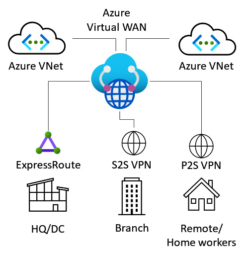
Figure 6.12 – Azure Virtual WAN
Azure Virtual WAN supports the following capabilities:
- Point-to-Site (P2S) VPN connectivity
- Site-to-Site (S2S) VPN connectivity
- ExpressRoute connectivity
- VPN and ExpressRoute interconnectivity
- SD-WAN connectivity
- Intra-cloud connectivity
- Intra-VNet connectivity
- Encryption
- Routing and traffic control
- Azure Firewall
This can be thought of as an any-to-any-type connectivity solution.
To implement an Azure virtual WAN, the high-level steps are as follows:
- Create a Virtual WAN resource.
- Create a Virtual WAN hub.
- Create a Virtual WAN site.
- Connect spoke endpoints to the hub.
- Download a configuration file.
- Validate connectivity through the hub and spoke endpoints.
In this section, we looked at Azure Virtual WAN and concluded the topic of network connectivity in Azure. The following section will look at implementing network protection in Azure.
Implementing network protection in Azure
This section will look at the network protection options available in Azure. This will cover NSGs, application security groups (ASGs), and the Azure Firewall; we will look at the use cases, how they work, and their capabilities.
This section will look at NSGs as the first skill area.
NSGs
An NSG is a packet filter approach controlling traffic flow into and out of resources such as VMs.
A set of inbound and outbound rules filters network traffic, denying all traffic unless explicitly allowed.
An NSG evaluates whether access is allowed or denied based on five data points (the 5-tuple method); these data points are as follows:
- Source
- Source port
- Destination
- Destination port
- Protocol
NSGs are represented in the following diagram:
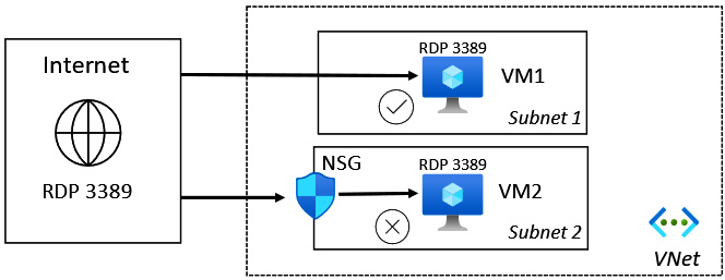
Figure 6.13 – NSGs
NSGs can be associated with a network interface or a subnet, but not a VNet. A subnet or network interface can only have one NSG assigned; an NSG can be associated with multiple subnets or network interfaces.
NSG association is represented in the following diagram:

Figure 6.14 – NSG association
Each NSG rule is numbered; the lowest number will be evaluated first and will determine based on the data points if a connection to the destination is allowed or denied.
Each NSG has a set of default rules that cannot be modified or removed; you should add custom rules with a lower number to have these overrides evaluated before the default rules. The final default rule that will be enforced is a deny-all rule.
An NSG can only be used to protect resources in the same subscription and region as the NSG; if you need to perform centralized network protection across highly distributed VNets and across multiple regions, Azure Firewall can be used.
This section looked at NSGs. In the next section, we will look at ASGs.
ASGs
An ASG provides a set of application-/workload-specific rules that can be associated with an NSG. In a nutshell, we base ASG traffic filter rules on business logic layer names rather than IP addresses or ranges. This is intended to simplify network protection rules by determining access at the business logic layer.
An ASG provides simplified network security micro-segmentations. We can apply a single NSG to all subnets on the NSG for full traffic analytics via flow logs. We then apply ASGs, with each VM being made a member of the appropriate ASG based on its role or network segmentation; this allows granular VM network interface layer control for both east/west and north/south traffic.
This approach is achieved through traffic filter rules based on the business logic and your application topology rather than the network address space topology. It takes a declarative/intent base approach. Rather than defining specific network IPs to be included in the rule, you define the business logic name layer groups you intend to filter traffic for and let Microsoft handle the complexities of the IP rules required. This is represented in the following diagram:
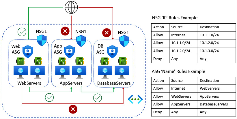
Figure 6.15 – ASG association
We can link this approach to the DNS concept, which uses names instead of IP addresses. In DNS, we may not know the IP address of a server, and its IP address may change, so we focus on business logic, meaning whatever the resource name is (that is constant), return the IP address (that can be variable). We can therefore use the same approach in ASGs to assign an alias or nickname, referred to as a moniker, to a group of VM resources and set a traffic filter rule based on the monikers rather than a network address.
This section looked at ASGs. In the next section, we will look at Azure Firewall.
Azure Firewall
Azure Firewall is a cloud-based Microsoft-managed firewall-as-a-service (FWaaS) solution. It provides centralized Layer 3/Layer 7 protection and control policies. Unlike an NSG, it works across subscriptions and regions.
Traffic control is through UDRs and can provide segmentation of networks for traffic control.
A typical Azure Firewall network topology is represented in the following diagram:
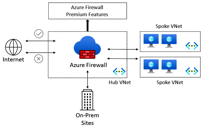
Figure 6.16 – Azure Firewall
Some of the capabilities of Azure Firewall are outlined here:
- Destination NAT (DNAT)
- Source NAT (SNAT)
- Intrusion Prevention System (IPS)
- Transport layer security (TLS) inspection
- Uniform Resource Locator (URL) filtering
Firewall Manager is another service that can be utilized. It provides centralized policy configuration and management for multiple deployed Azure firewalls across different Azure regions and subscriptions.
In this section, we looked at Azure Firewall and concluded the topic of network protection in Azure. The following section will look at implementing name resolution in Azure.
Implementing name resolution in Azure
This section will look at the name resolution options available in Azure; we will also cover the topic of cross-premises/hybrid name resolution.
Azure DNS is the first skill area we will look at in this section.
Azure DNS
Azure DNS is a Microsoft-managed DNS-as-a-service solution for name resolution of Azure resources. You do not need to provide your own DNS servers for name resolution.
The Azure DNS service provides hosting for both your public DNS zones and private DNS zones, for which Azure can be authoritative, as detailed here:
- Public DNS: Hosts your DNS domains and provides name resolution for DNS domains that are internet-facing
- Private DNS: Allows hostname resolution within a VNet and between VNets
Once your DNS zones are migrated to Azure DNS, Microsoft’s DNS name servers will respond to queries for resources in these zones. Anycast DNS is used by the DNS service, meaning the query will be responded to by the DNS server that is closest geographically to the query.
The Azure portal, Azure PowerShell, or the Azure CLI can be used to create and manage Azure public and private zones.
These are the high-level steps to implement a public zone:
- Create a public zone.
- Add records to the zone.
- Validate name resolution for the zone.
These are the high-level steps to implement a private zone:
- Create a private zone.
- Link (publish) the zone to the VNets for name resolution using the Azure DNS service.
- Add records to the zone; if required, enable auto-registration.
- Validate name resolution for the zone.
For Azure DNS private zones, the following capabilities are provided:
- Automatic registration from a private zone linked to the VNet of VMs
- DNS resolution forwarding across private zone-linked VNets
- Reverse DNS lookup within the scope of the VNet
The following are some limitations of Azure DNS:
- There is no support for conditional forwarding; you should use your own DNS servers in place of this if this capability is required
- There is no support for Domain Name System Security Extensions (DNSSEC); you should use your own DNS servers in place of this if this capability is required
- There is no support for zone transfers; you should use your own DNS servers in place of this if this capability is required
- Reverse DNS is only possible with private address spaces linked to the VNet
- You can only link one VNet to a private zone
- There is a limit to the number of zones and records per subscription
Next, we will look at Windows Server DNS on Azure VMs and integration with Azure DNS.
Windows Server DNS on Azure VMs
The DNS server role can be installed on Azure VMs running the Windows Server OS using Server Manager in the same way as for an on-premises installation.
You can specify that a VNet uses your own Windows DNS servers instead of Azure DNS; these DNS servers could be Azure VM DNS servers or on-premises DNS servers connected to the Azure VNet.
You may decide to implement Windows Server DNS on Azure VMs to replace or in addition to Azure DNS in the following scenarios:
- A need for name resolution between VNets
- A need for name resolution of Azure from on-premises
- A need for conditional forwarders
- A need for zone transfers
Your own Windows DNS servers can be set in the Azure VNet DNS servers | Custom setting, as shown in the following diagram:

Figure 6.17 – Custom DNS server setting
The following diagram represents hybrid name resolution using Windows Server DNS and Azure DNS:
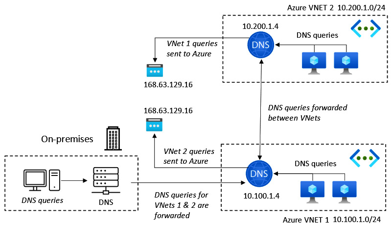
Figure 6.18 – Hybrid name resolution
In the preceding diagram, Windows Server DNS servers attached to a VNet can respond to queries for its on-premises domain, such as its own authoritative zones, and use the recursive resolvers in Azure for forwarded queries that need to resolve Azure hostnames that it will not have a record of.
The address to use for Azure DNS recursive DNS resolvers is 168.63.129.16.
Next, we will look at the split-horizon DNS in Azure.
Split-horizon DNS in Azure
Split-horizon DNS uses the same name to resolve the names of internal and external resources. It is also known as split-brain DNS.
This works by having two zones for the same domain; one is used for internal resource queries, and the other for external resource queries.
In Azure DNS, this is implemented by creating two zones of the same name, such as milesbetter.solutions.
The milesbetter.solutions zones should be created and configured as follows:
- Private zone records:
|
Host |
Record type |
IP address |
|
pizzapp |
CNAME |
mbs1.milesbetter. solutions |
|
mbs1 |
A |
10.5.1.4 |
- Public zone records:
|
Host |
Record type |
IP address (public) |
|
pizzapp |
A |
123.456.789 |
This configuration returns the correct lookups and information based on whether clients are on the internal or external network.
In this section, we looked at Windows Server DNS on Azure VMs and concluded the topic of implementing name resolution in Azure. In the next section, we will complete a hands-on exercises section to re-enforce some of the concepts covered in this chapter.
Hands-on exercises
To support your learning with some practical skills, we will utilize concepts and understanding gained from the earlier sections of this chapter and put them into practical application.
We will look at the following exercises:
- Exercise—Implementing an Azure VNet
- Exercise—Implementing an NSG
- Exercise—Implementing Azure DNS
- Exercise—Implementing an Azure VPN gateway
- Exercise—Implementing VNet peering
Getting started
To get started with this section, if you do not already have an Azure subscription, you can create a free Azure account at https://azure.microsoft.com/free. This free Azure account provides the following:
- 12 months of free services
- USD $200 credit to explore Azure for 30 days
- 25+ services that are always free
Let’s move on to the exercises for this chapter.
Exercise – Implementing an Azure VNet
In this exercise, we will look to create an Azure VNet.
Follow these steps to create a VNet:
- Log in to the Azure portal: https://portal.azure.com. You can alternatively use the Azure desktop app: https://portal.azure.com/App/Download.
- In the search bar, type virtual networks; click on Virtual networks from the list of services shown:
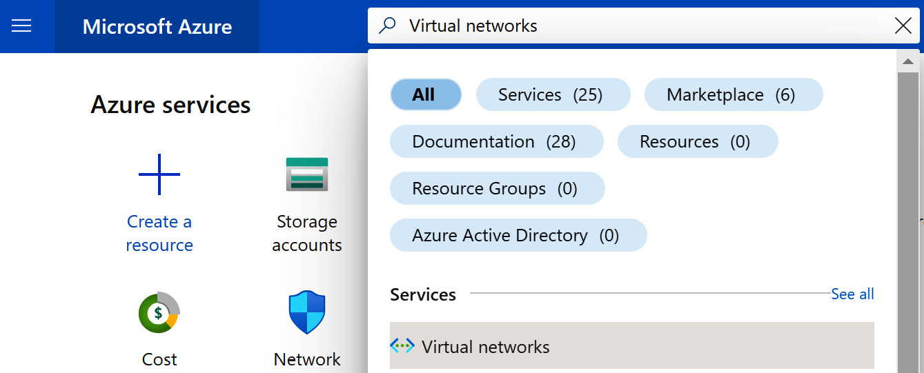
Figure 6.19 – Searching for the Virtual networks resource
- From the Virtual networks blade, click on the + Create option from the top menu of the blade, or use the Create virtual network button at the bottom of the blade. Optionally, click the Learn more hyperlink for further information and learning:

Figure 6.20 – Creating a VNet
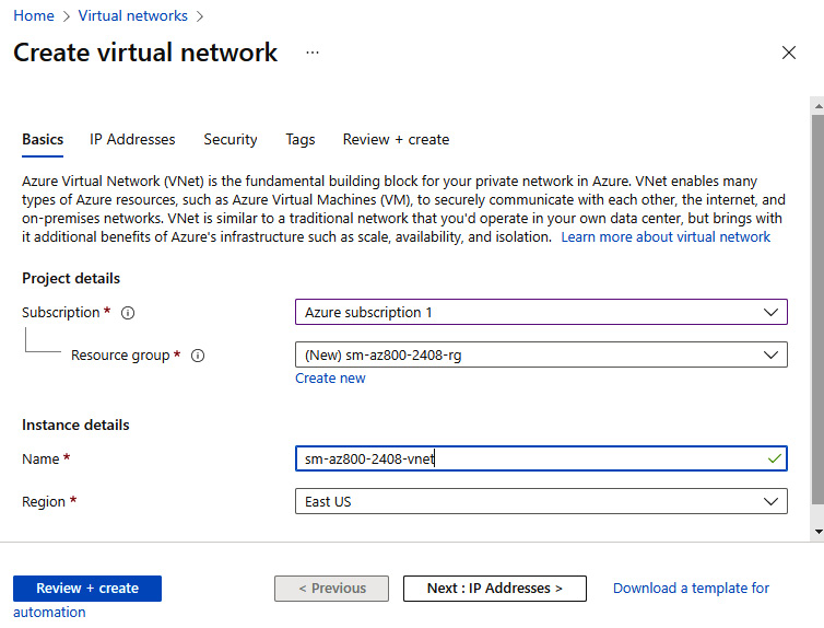
Figure 6.21 – VNet Basics tab
- Click Next: IP Addresses.
- Create an IPv4 address space and subnets; use existing defaults for this exercise:
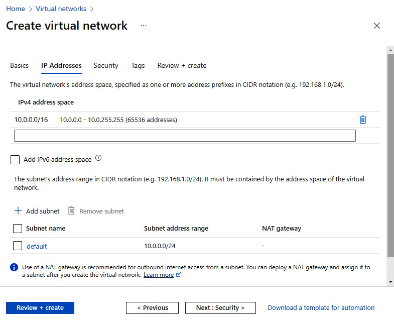
Figure 6.22 – VNet IP Addresses tab
- Click Next: Security.
- Leave the default setting of Disable for BastionHost, DDoS Protection Standard, and Firewall:
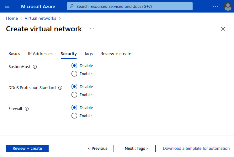
Figure 6.23 – VNet Security tab
- Click Next: Tags and skip entering any information for this exercise. Then, click Next: Review + create:

Figure 6.24 – VNet Tags tab
- On the Review + create tab, review your settings; you may go back to the previous tabs and make any edits if required. Once you have confirmed your settings are as needed, you can click Create:
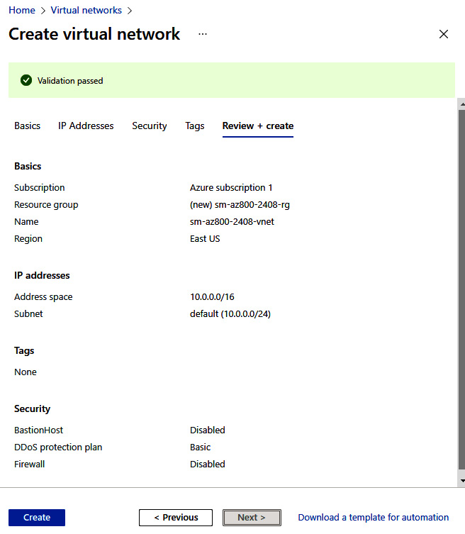
Figure 6.25 – VNet Review + create tab
- You will receive a Deployment succeeded notification. Click on Go to resource or navigate to the Virtual networks blade:
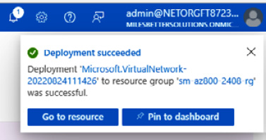
Figure 6.26 – VNet deployment succeeded
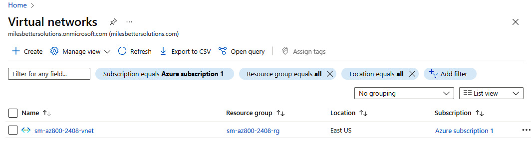
Figure 6.27 – Created VNet
With this, we have completed this exercise. It taught us the skills needed to implement an Azure VNet. The following exercise will look at implementing an NSG.
Exercise – Implementing an NSG
In this exercise, we will look to create a VM and associate an NSG at the subnet level. We will then add rules to allow Remote Desktop Protocol (RDP) access and deny outbound internet access.
In the following sub-sections, you can see the procedure to complete the exercise, segregated into tasks for a better understanding.
Task 1 – Accessing the Azure portal
- Log in to the Azure portal: https://portal.azure.com. You can alternatively use the Azure desktop app: https://portal.azure.com/App/Download.
Task 2 – Creating a VM

Figure 6.28 – Searching for the VM’s resource
- From the Virtual machines blade, click + Create and then Virtual machine from the top menu of the blade. Optionally, click the Learn more about hyperlinks for further information and learning:
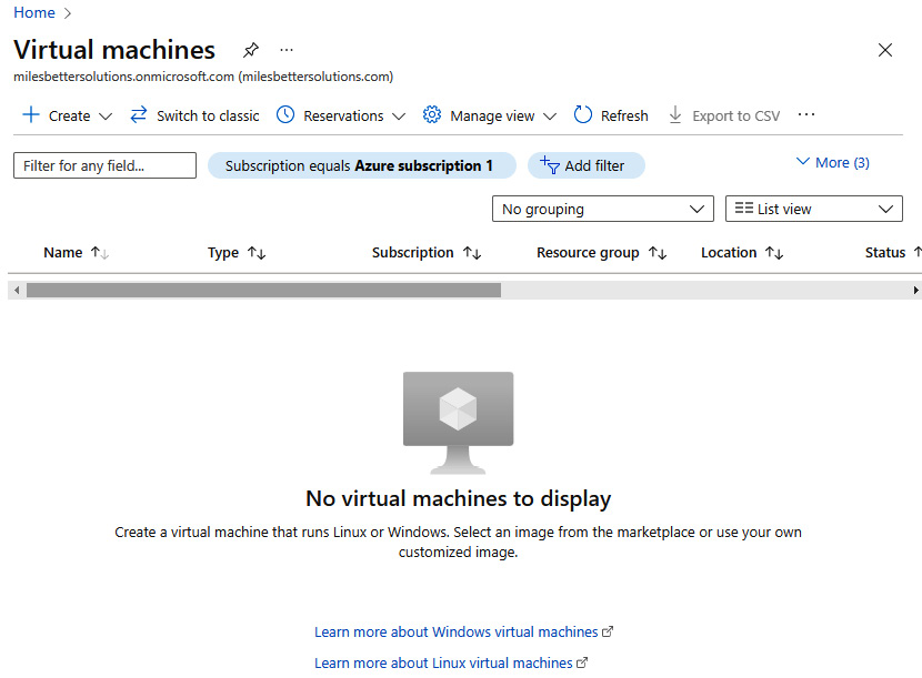
Figure 6.29 – Creating a VM
- Set Project details values of Subscription and Resource group as required.
- Set Instance details values as follows:
- Virtual machine name: Enter a name
- Region: Select a region
- Availability options: Leave default selected
- Security type: Leave default selected
- Image: Select a Windows Server image
- Size: Leave default selected or select as required:

Figure 6.30 – Creating a VM: settings
- Set the Administrator account username and password as required:
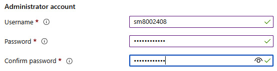
Figure 6.31 – Creating a VM: settings (continued)
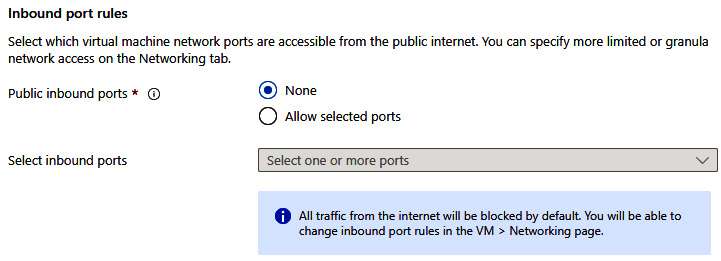
Figure 6.32 – Creating a VM: settings (continued)
- For this exercise, set Licensing at the unchecked default; that is, No use of an existing Windows Server license.
- Click Next: Disks.
- For this exercise, leave the Disks tab at the default settings:
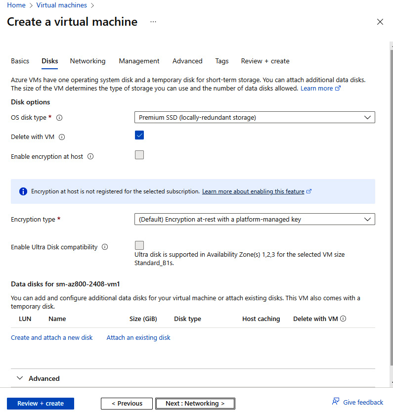
Figure 6.33 – Creating a VM: settings (continued)
- Click Next: Networking.
- From Network interface, set the following:
- Virtual network: Use the default provided
- Subnet: Use the default provided
- Public IP: Click Create new, enter a name, and click OK
- NIC network security group: Select None
- Delete public IP and NIC when VM is deleted: Check to enable/allow
- Leave all other settings at their defaults:
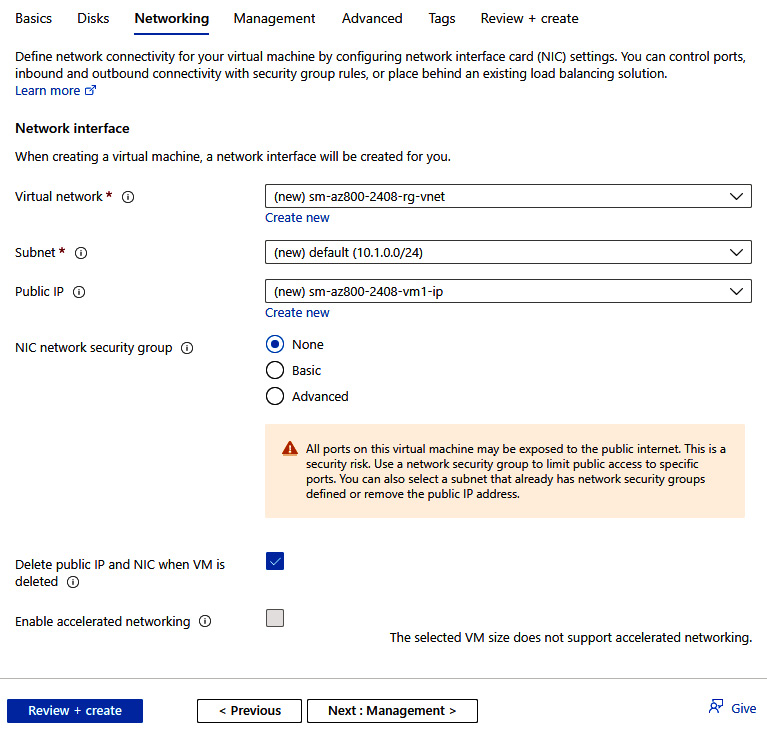
Figure 6.34 – Creating a VM: settings (continued)
- Click Next: Management.
- Leave the settings at their defaults.
- Click Next: Advanced.
- Leave the settings at their defaults.
- Click Next: Tags and skip entering any information for this exercise. Then, click Next: Review + create.
- On the Review + create tab, review your settings; you may go back to the previous tabs and make any edits if required. Once you have confirmed your settings are as needed, you can click Create:

Figure 6.35 – Creating a VM: Review + create tab

Figure 6.36 – VM deployment succeeded
Task 3 – Creating an NSG
- In the search bar, type in network security groups; click Network security groups (not Network security groups (classic)) from the list of services:
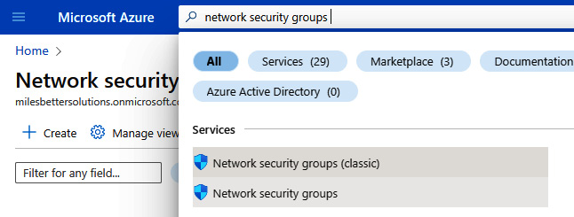
Figure 6.37 – Searching for the NSG resource
- From the Virtual machines blade, click + Create from the top menu of the blade. Optionally, click the Learn more hyperlink for further information and learning:
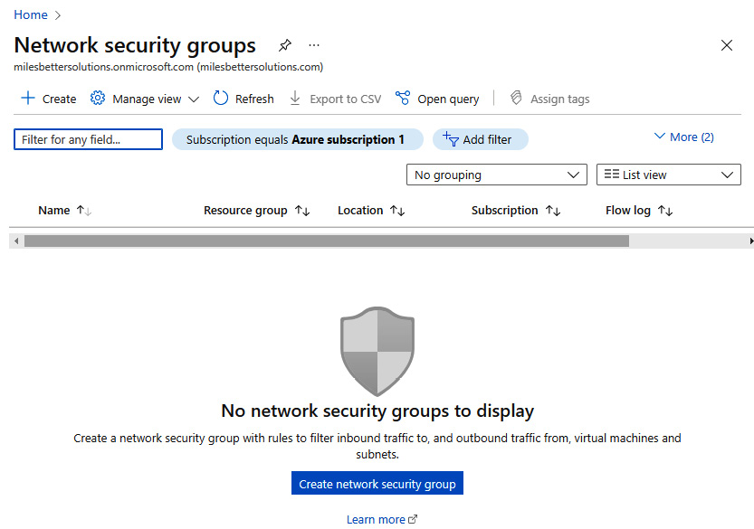
Figure 6.38 – Creating an NSG
- Complete the Project details and Instance details settings as required. Set Region the same as where the VM was created:

Figure 6.39 – Creating an NSG: settings
- Click Next: Tags and add any tags as required, then click Next: Review + create.
- On the Review + create tab, review your settings; you may go back to the previous tabs and make any edits if required. Once you have confirmed your settings are as needed, you can click Create.
- You will receive a notification that the resource was created successfully.
- Click Go to resource from the Deployment blade; alternatively, navigate to the Azure NSG instance.
Task 4 – Associating an NSG with a subnet
- From the created Network security group blade of the instance created, click Subnets under Settings:

Figure 6.40 – Created NSG
- Click + Associate from the top toolbar:
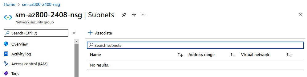
Figure 6.41 – Associating an NSG
- Select the Virtual network and Subnet configurations of the VM you created in the previous exercise from the Associate subnet blade:
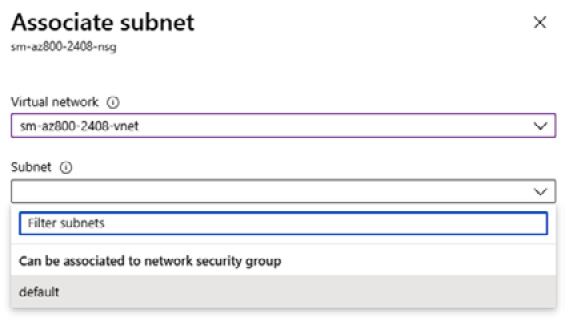
Figure 6.42 – Associating an NSG (continued)
Task 5 – Adding an inbound rule to allow RDP access
- Navigate to the NSG created in this exercise. Notice that all inbound connections are denied unless their source is VirtualNetwork or Azure LoadBalancer. We will address this in the next task.
- From the Network security groups blade, click Inbound security rules under Settings:
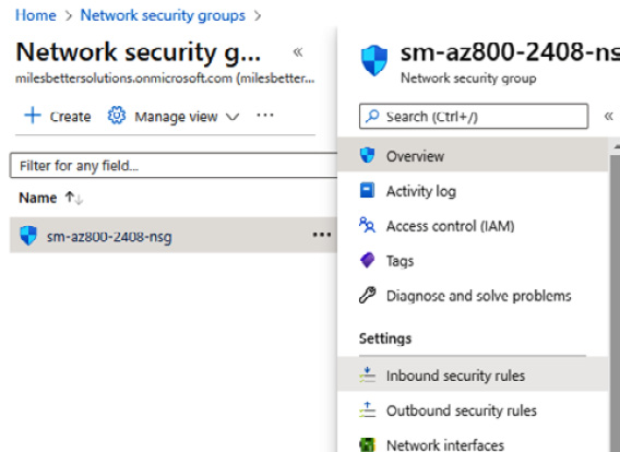
Figure 6.43 – Created NSG
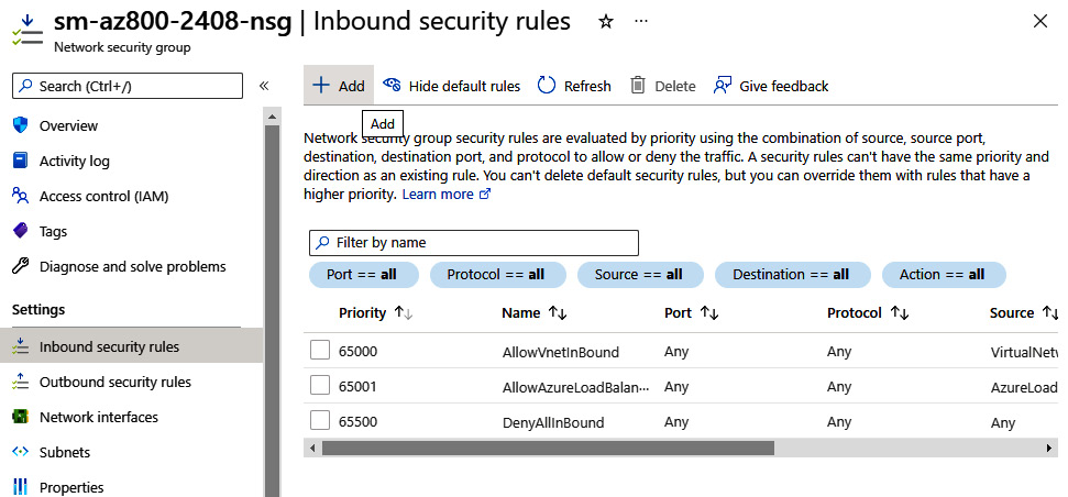
Figure 6.44 – Adding an NSG
- Open a browser and in Google, type what's my IP and note your IP for the next step.
- From the Add inbound security rule blade, set the following:
- Source: Select IP Addresses
- Source IP addresses/CIDR ranges: Set this to your IP from the Google result for your IP in step 4 of this task
- Source port ranges: Leave at default of * (asterisk symbol)
- Destination: Leave at default of Any
- Service: Select RDP
- Action: Ensure Allow is set
- Priority: Leave at default of 100
- Name: Provide a name, such as AllowInbound_RDP_KnownIP
- Description: Enter one as required
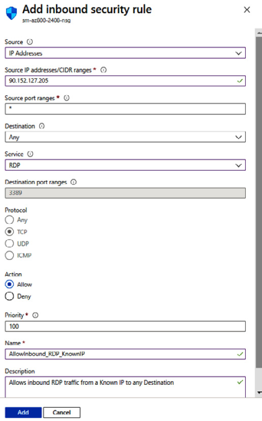
Figure 6.45 – Adding an NSG (continued)
Figure 6.46 – NSG created
Task 6 – Accessing the VM via an RDP connection
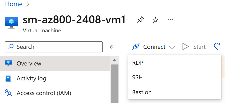
Figure 6.47 – VM connection
- On the Connect blade, click the Download RDP File button:
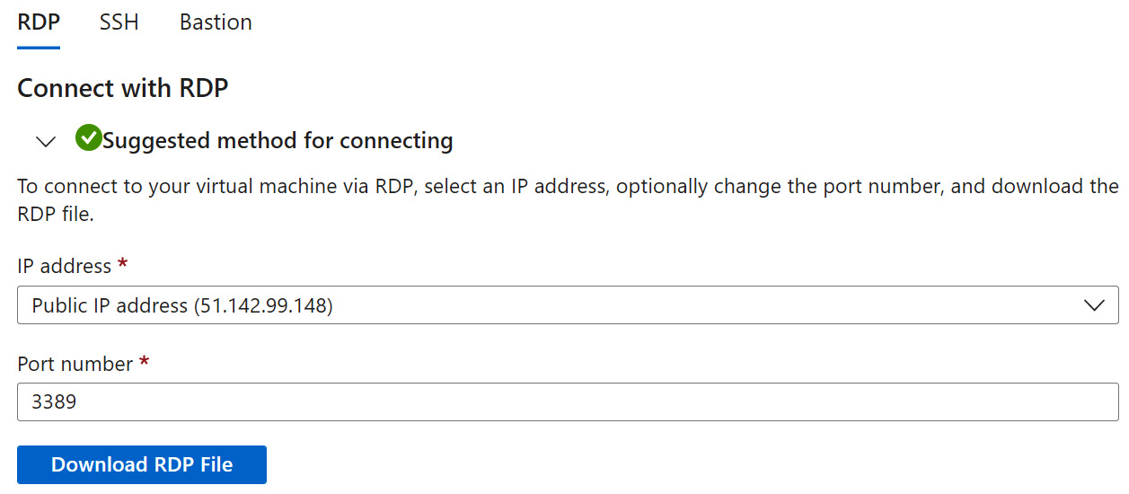
Figure 6.48 – VM connection (continued)
- Open the RDP file from where it is saved.
- Click Connect to start an RDP session that is allowed by the ruleset in this task:

Figure 6.49 – Remote desktop connection
Task 7 – Accessing the internet from the VM
- While logged in to the VM, open a browser, and confirm you reached the internet by visiting a site such as https://docs.microsoft.com. You may need to adjust the browser security settings. We will restrict this access to the internet in the next exercise:
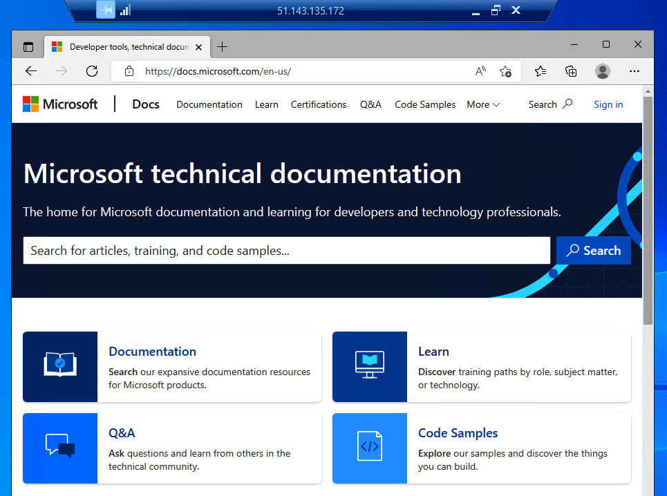
Figure 6.50 – Accessing the internet
Task 8 – Adding an outbound rule to deny internet access
- On the Virtual machine blade, click Networking under Settings; you will see from the Outbound port rules tab that all outbound connections are allowed to the internet.
- On the Outbound port rules tab, click Add outbound port rule.
- On the Add outbound security rule blade, leave all other options at their defaults apart from the following:
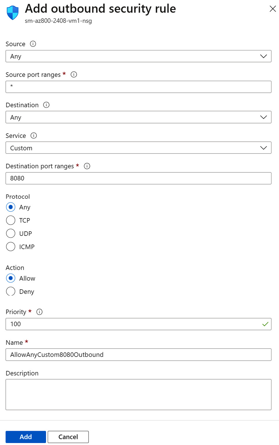
Figure 6.51 – Adding an NSG rule
- Click Add.
- You will receive a notification that the rule was created successfully.
- The new rule will be shown listed:
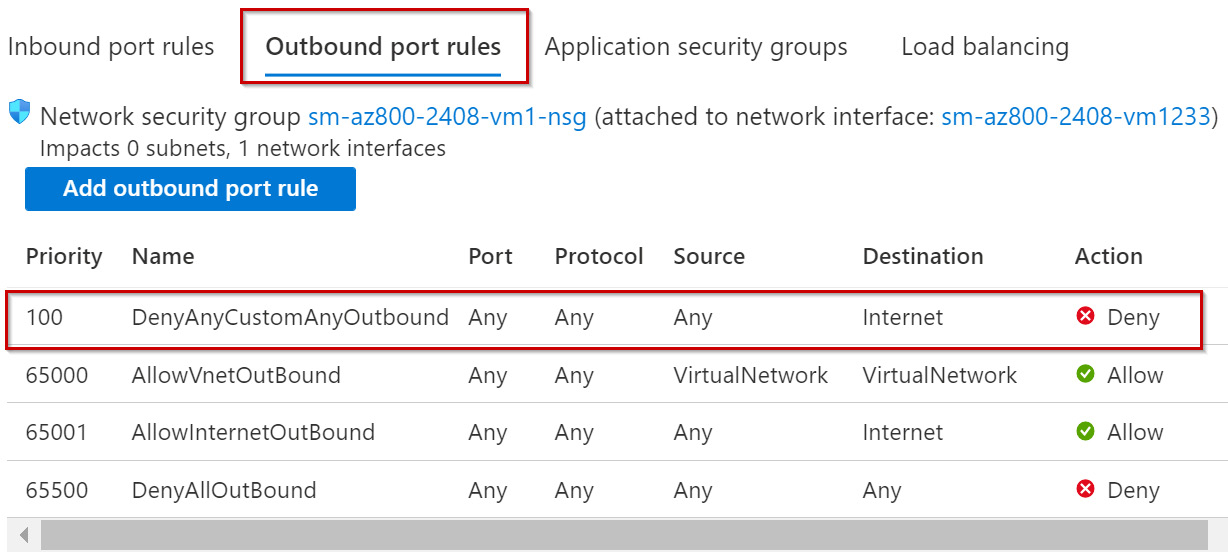
Figure 6.52 – New NSG rule added
- In the VM, open a browser again and confirm you can no longer reach the internet by visiting a site such as https://docs.microsoft.com.
- This time, you will see a message from the browser such as Hmmm… can’t reach this page:
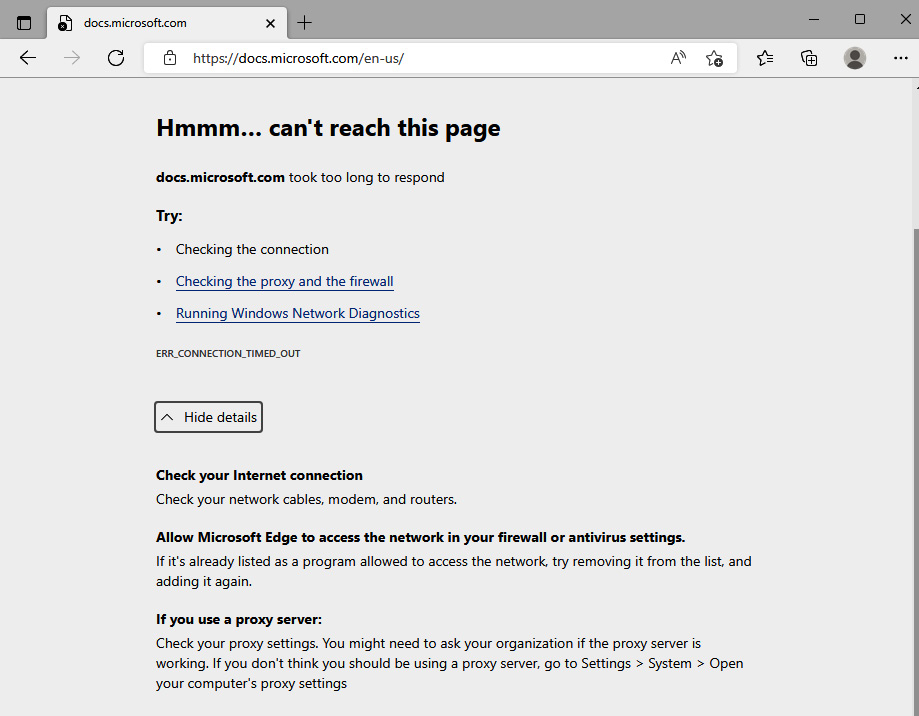
Figure 6.53 – Internet access denied
With this, we have completed this exercise. This exercise taught us the skills needed to implement and configure an NSG. The following exercise will look at implementing Azure DNS.
Exercise – Implementing Azure DNS
This exercise will look at creating and configuring public and private zones in Azure DNS.
In the following sub-sections, you can see the procedure to complete the exercise, segregated into tasks for a better understanding.
Task 1 – Accessing the Azure portal
- Log in to the Azure portal: https://portal.azure.com. You can alternatively use the Azure desktop app: https://portal.azure.com/App/Download.
Task 2 – Creating a public zone
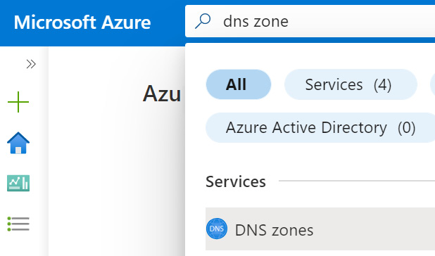
Figure 6.54 – Searching for the Azure DNS zones resource
- On the DNS zones blade, click + Create from the top menu of the blade. Optionally, click the Learn more hyperlink for further information and learning:
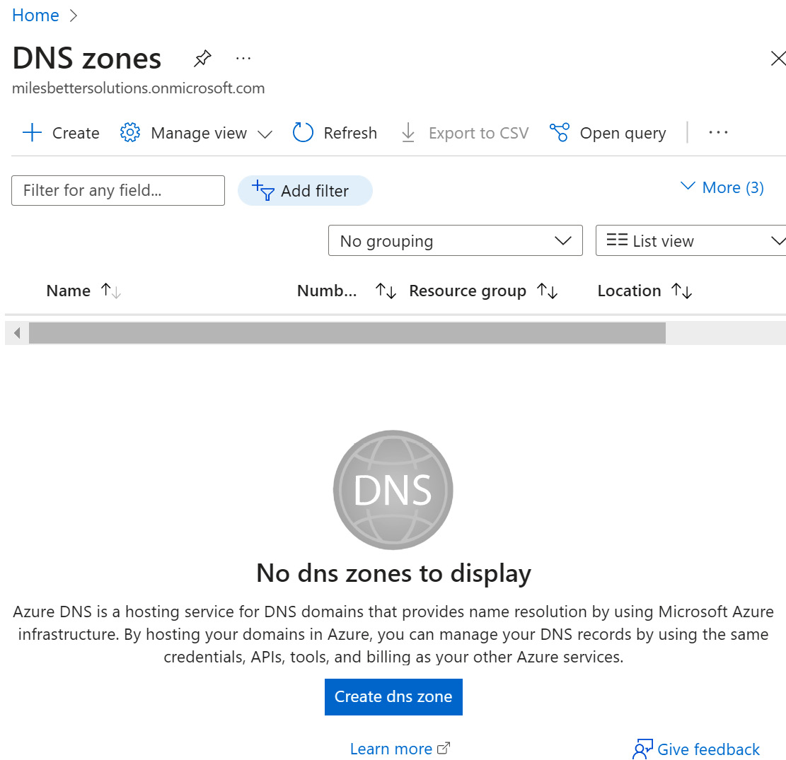
Figure 6.55 – Creating a DNS zone
- Complete the Project details and Instance details settings as required.
- Click Next: Review + create.
- On the Review + create tab, review your settings; you may go back to the previous tabs and make any edits if required. Once you have confirmed your settings are as needed, you can click Create.
- You will receive a notification that the resource was created successfully.
- Click Go to resource from the Deployment blade; alternatively, navigate to the DNS zones blade.
Task 3 – Adding records
- Search All resources for the zone created or navigate to the DNS zones blade and open your created zone.
- From the DNS zones blade, click + Record set from the top menu of the blade.
- From the Add record set blade, enter the required information, and click OK.
- From the DNS zones blade, review your record added:

Figure 6.56 – Adding DNS records
For this exercise, we have used an example name and record; you should use an example that meets your requirements.
- To test the name resolution, open Command Prompt and run the following command:
nslookup az800.milesbetter.com ns1-01.azure-dns.com
Replace with the information for the fully qualified domain name (FQDN) and name server that is relevant to your environment.
- You should see a response as follows:

Figure 6.57 – nslookup command output
Task 4 – Creating a private zone
- In the search bar, type in private dns zone; click Private DNS zones from the list of services.
- On the Private DNS zones blade, click + Create from the top menu of the blade. Optionally, click the Learn more hyperlink for further information and learning.
- Complete the Project details and Instance details settings as required.
- Click Next: Review + create.
- On the Review + create tab, review your settings; you may go back to the previous tabs and make any edits if required. Once you have confirmed your settings are as needed, you can click Create.
- You will receive a notification that the resource was created successfully.
- Click Go to resource from the Deployment blade; alternatively, navigate to the Private DNS zones blade.
Task 5 – Linking VNets
- Search All resources for the zone created or navigate to the Private DNS zones blade and open your created zone.
- From the Private DNS zones blade, under Settings, select Virtual network links.
- From the Virtual network links blade, click + Add from the top menu of the blade.
- Enter a Link name value.
- Select a Subscription type.
- Select the Virtual network configuration you will link the zone to.
- Optionally, select whether to enable auto registration.
- Select OK.
- You will receive a notification that the resource was created successfully.
- Click Go to resource from the Deployment blade; alternatively, navigate to the Private DNS zones blade.
- Adding and testing records is the same process as the steps we completed in the Creating a public zone task.
With this, we have completed this exercise. This exercise taught us the skills needed to implement Azure DNS. This next exercise will look at creating an Azure VPN gateway.
Exercise – Implementing an Azure VPN gateway
In this exercise, we will look to create an Azure VPN gateway for hybrid connectivity to on-premises resources.
For this exercise, you will require the following in place:
- An Azure VNet; you may use an existing VNet or the VNet from the previous exercise in this chapter on VNet creation
In the following sub-sections, you can see the procedure to complete the exercise, segregated into tasks for a better understanding.
Follow the steps in the following tasks to create a VPN gateway (VNet gateway).
Task 1 – Accessing the Azure portal
- Log in to the Azure Portal: https://portal.azure.com. You can alternatively use the Azure Desktop App: https://portal.azure.com/App/Download.
Task 2 – Creating a VNet gateway
- In the search bar, type virtual network gateways; click on Virtual network gateways from the list of services shown:

Figure 6.58 – Searching for the VNet gateway resource
- From the Virtual network gateways blade, click on the + Create option from the top menu of the blade, or use the Create virtual network gateway button at the bottom of the blade. Optionally, click the Learn more about Virtual network gateway hyperlink for further information and learning.

Figure 6.59 – Creating a VNet
- On the Create virtual network gateway blade, select your subscription to use for the resources for this exercise, then select your VNet; this will auto-populate the Resource group field:
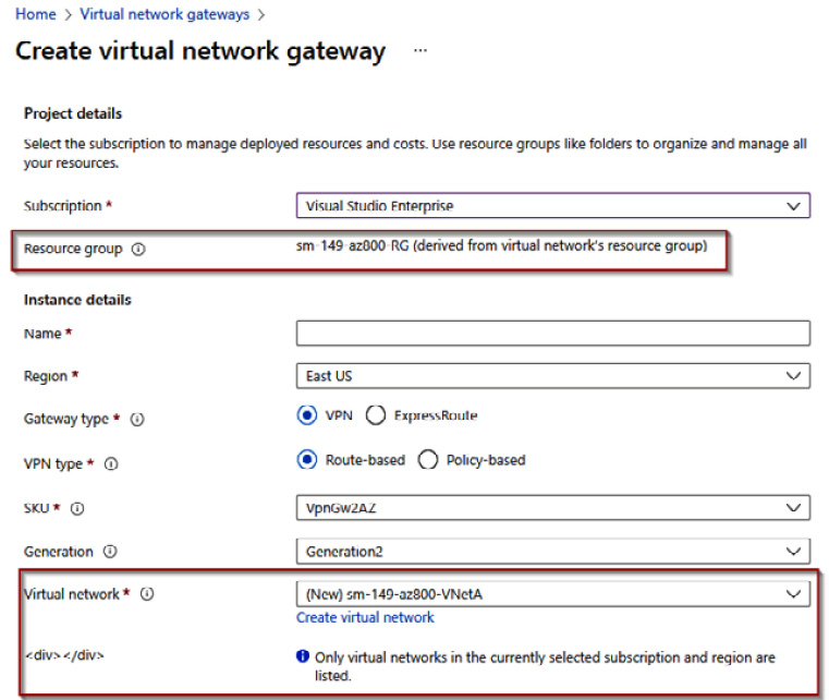
Figure 6.60 – Creating a VNet (continued)
- Complete the following settings, and leave all other entries at their defaults:
- Name: Enter your chosen name
- Region: This must be left at the region for the VNet being used
- SKU: VpnGw1
- Public IP address name: Enter your chosen name:
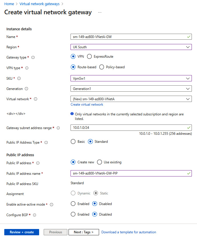
Figure 6.61 – Creating a VNet (continued)
- Click Next: Review + create.
- On the Review + create tab, review your settings; you may go back to the previous tabs and make any edits if required. Once you have confirmed your settings are as needed, you can click Create:
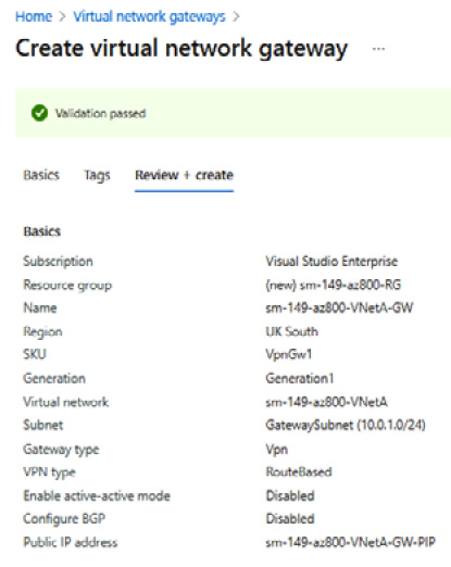
Figure 6.62 – Reviewing settings
- The creation process may take up to 1 hour.
- You will receive a notification that the resource was created successfully.
- Click Go to resource from the Deployment blade; alternatively, navigate to the Virtual network gateways blade to review the resource created.
With this, we have completed this exercise. This exercise taught us the skills needed to implement an Azure VPN gateway. In the next exercise, we look at implementing VNet peering.
Exercise – Implementing VNet peering
In this exercise, we will look to add a peering relationship between two VNets so that resources can communicate across the Microsoft backbone without traversing the public internet.
For this exercise, you will require the following in place:
- Two Azure VNets; you may use existing VNets or the VNet from the previous exercise in this chapter on VNet creation and create another to peer with
Follow these steps to add VNet peering.
Task – Add VNet peering
- Log in to the Azure portal: https://portal.azure.com. You can alternatively use the Azure desktop app: https://portal.azure.com/App/Download.
- Navigate to the Virtual networks blade and click your first VNet to set up, peering from the list of VNets. Then, click Peerings under the Settings section:
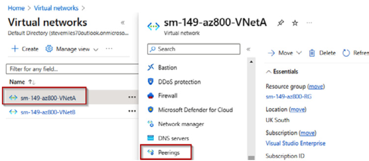
Figure 6.63 – Selecting the first VNet to peer
- From the Virtual networks peerings blade, click on the + Add option.
- From the Add peering blade, set the following; leave all others at defaults:
- This virtual network - Peering link name: Enter your chosen name
- Remote virtual network – Peering link name: Enter your chosen name
- Virtual Network: Select the VNet you wish to establish a peer with; that is, the remote VNet
- You will receive a notification that peerings were added successfully:

Figure 6.64 – Peering added successfully
- From the Peerings blade, you will see that the peering has been added, the peering status is Connected, and the remote VNet peer is shown:

Figure 6.65 – VNet peerings
With this, we have completed this exercise. This exercise taught us the skills needed to implement Azure VNet peering. Now, let’s summarize this chapter.
Summary
This chapter aimed to take your knowledge beyond the exam objectives; we added new skills and learning with the content provided. This further develops your knowledge and skills for on-premises network infrastructure services and enables you to be prepared for a real-world, day-to-day hybrid environment-focused role.
The content in this chapter covered information for the Implement and manage Azure network infrastructure skills outline section for the AZ-800 Administering Windows Server Hybrid Core Infrastructure exam.
We learned about some of the core network services components in Azure, such as implementing VNets and DNS, as well as looking at connectivity options and network protection aspects. A hands-on exercise then finished the chapter to develop your skills further.
The next chapter teaches about implementing and managing Azure network infrastructure.
Further reading
This section provides links to additional study references and additional exam information:
- Microsoft Certified: Windows Server Hybrid Administrator Associate: https://docs.microsoft.com/en-us/learn/certifications/windows-server-hybrid-administrator/
- Exam AZ-800: Administering Windows Server Hybrid Core Infrastructure: https://docs.microsoft.com/en-us/learn/certifications/exams/az-800
- Exam AZ-800: Skills outline: https://query.prod.cms.rt.microsoft.com/cms/api/am/binary/RWKI0r
- Microsoft Learn: https://docs.microsoft.com/en-us/learn/paths/implement-operate-premises-hybrid/
Skills check
Challenge yourself with what you have learned in this chapter:
- What is an Azure VNet?
- Which IP types are supported to be created?
- How many IP addresses in a VNet subnet are reserved, and what are their purposes?
- How does a VM communicate with other resources in Azure?
- What is VNet peering?
- Which VPN types are supported to connect to Azure?
- What is a VPN gateway, and which types can be created?
- What is ExpressRoute, and what are its benefits?
- What is Azure Virtual WAN?
- What is Azure Extended Network, and what is a use case?
- Explain VNet routing in Azure and the purpose of NVAs.
- What are NSGs and ASGs?
- What is Azure Firewall?
- What is Azure DNS?
- What are the limitations of Azure DNS, and when might Windows Server DNS still be required?