Chapter 2. Creating Simple Graphics
This chapter teaches you to use Adobe Flash CS3 Professional’s drawing tools to create basic shapes from lines and areas of color—in Flash terminology, strokes and fills. Flash offers natural drawing tools that imitate the feel of working on paper with a pencil or brush; geometric-shape tools that create predefined shapes; and a pen tool that lets you draw with precision, using Bézier curves.
These tools let you create three types of shapes. Tools set to Merge Drawing mode create raw shapes—shapes that interact with other raw shapes on the same layer (you’ll learn about shape interactions in Chapter 5). Tools set to Object Drawing mode create editable shapes that don’t interact with other shapes. Flash CS3 introduces a new type of shape, the primitive-shape. Two new tools, the rectangle- and oval-primitive tools, create non-interactive shapes with a set of defining parameters. You can edit a primitive’s parameters (changing the roundness of a rectangle’s corners, for example), but you can’t freely edit a primitive’s outline (turning an oval into a free-form blob, for example).
Once you create a shape, you can edit it (see Chapter 4). You can also import graphics from other programs (see Chapter 14).
Touring the Tools
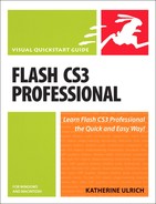
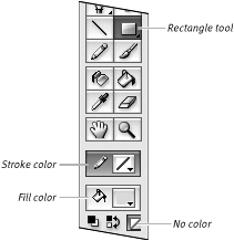
The Tools panel holds all the tools you need to create and modify graphic elements (Figure 2.1). Flash CS3 gives you tools for creating graphic elements, for scrolling the Stage and zooming in and out, and for setting colors for the elements you create.
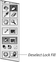
Figure 2.1. The Tools panel contains tools for drawing, editing, and manipulating graphic elements in Flash. Click the current transform-tool icon to view the free-transform and gradient-transform tools; click the current Bézier-tool icon to view the pen and path-editing tools; click the current geometric-shape–tool icon to choose the rectangle, oval, rectangle-primitive, oval-primitive, or polystar tool.
You click a tool to select it for use. If the selected tool has options, the appropriate buttons and/or menus for choosing options and settings appear at the bottom of the Tools panel.
 Tip
Tip
• By default the Tools panel appears in single-column mode. Figure 2.1 shows the panel in space-saving two-column mode. Click the double-triangle icon in the panel window’s title bar to switch modes (Figure 2.2).
Figure 2.2. To change between a single- and double-column Tools panel, click the double triangles in the panel’s upper-left corner.
- With the Tools panel open, click a tool—for example, the brush tool.
The relevant modifiers for the selected tool appear at the bottom of the panel.
- Click a button or select an option to modify the way the selected tool works (Figure 2.3).
Figure 2.3. When you select a tool, its modifiers appear at the bottom of the Tools panel. Here the settings for using the brush appear. Click a button to toggle settings such as Merge mode; select a setting from a menu, such as Brush mode.

Tips
• Flash’s default setting makes tool tips active (when the pointer hovers over a tool, an identifying label appears). You can change the tool tip setting in the Preferences dialog: Select the General category, select (or deselect) the Show Tooltips check box, and click OK to close the dialog. (For details on opening the Preferences dialog, see Chapter 1.)
• In addition to displaying tool names, tool tips show keyboard shortcuts. As you get more familiar with the tools, activating them from the keyboard will speed your operations.
• To close the open Tools panel (or open it when it’s closed), Choose Window > Tools.
• The single-column Tools panel is very narrow, making it a good candidate for double-docking. Drag another panel window to the edge of the Tools panel to double-dock the two (for more details on docking, see Chapter 1).
Creating Solid Colors and Gradients
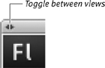
Although you can define fill and stroke colors from most color controls (see the sidebar “The Mystery of Color Controls”), the Color panel gives you the widest variety of options for defining fill and stroke colors. You can choose colors visually, by clicking a graphic representation of a color space—all the available colors in a given color-definition system; or you can choose colors numerically, by entering specific values for color components. You can also set a color’s transparency in the Color panel. To define new gradients, you must use the Color panel.
Before you define a color or gradient, you must choose whether the color or gradient applies to fills or strokes by activating the Fill Color control or the Stroke Color control. As you define new colors, Flash updates all the related color controls. If you define a new fill color, for example, that color becomes the current setting for all the tools that use fills.
To assign solid-color attributes in the Color panel:
- Access the Color panel (if it’s not open, choose Window > Color).
- From the Type menu, choose Solid.
- To choose a color space, from the panel’s options menu, choose one of the following:
• To define colors as mixtures of red, green, and blue, choose RGB.
• To define colors by percentage of hue, saturation, and brightness, choose HSB (Figure 2.4).
Figure 2.4. The Color panel lets you choose a color from the color-space window or enter values directly to define a color in the RGB or HSB color space. Choose the desired color space from the panel’s options menu.
- To determine where Flash applies the new color, do one of the following:
• To set a new stroke color, choose the Stroke Color control by clicking the pencil icon.
• To set a new fill color, choose the Fill Color control by clicking the paint-bucket icon.
To define a new color visually in the Color panel:
- With the Color panel open, choose a color space.
- Position the pointer over the desired hue in the color-space window.
- Click.
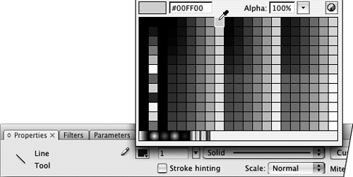
Flash places a crosshair cursor in the window where you clicked and selects the color within the crosshairs (Figure 2.5).
Figure 2.5. The Color panel displays a color-space window (A), a preview window for the new color (B), a luminosity/lightness slider (C), and a text field for entering the precise hex value of a color (D). Click in the color-space window to choose a new color visually.

Tip
• If you have trouble clicking exactly the right color, click and drag around within the color-space window. A preview of the new color appears above the old color in the preview window. When the color you want appears, release the mouse button. Flash enters the values for that color in the appropriate fields.
To define a new color numerically in the Color panel:
- With the Color panel open, choose a color space.
- To define a new color, do one of the following:
• For RGB colors, enter values from 0 to 255 for red, green, and blue in the R, G, and B fields (Figure 2.6).
Figure 2.6. Enter RGB values to specify the amount of red, green, and blue that make up the color. Enter HSB values to specify the color by hue, saturation, and brightness. The new color appears in the selected color control.

• For HSB, enter values for hue, saturation, and brightness in the H, S, and B fields.
To define a color’s transparency:
- With the Color panel open, define a color.
- Enter a value in the Alpha field (Figure 2.7).
Figure 2.7. Enter an Alpha value of less than 100 percent to define a transparent color.
A value of 100 (100 percent) results in a completely solid color; a value of 0 results in a completely transparent color.
- Open the Color panel.
- From the Color panel’s Type menu, choose Linear (Figure 2.8).
Figure 2.8. Choose Linear from the Type menu to access the tools for defining linear gradients.
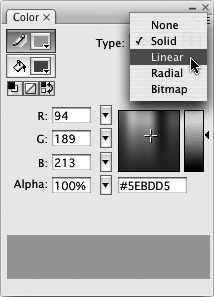
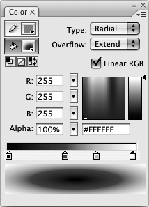
The tools and options for defining gradients appear (Figure 2.9). The default gradient starts with two pointers, black on the left and white on the right.
Figure 2.9. When you choose Linear or Radial as the Type, the Color panel displays the gradient-preview window, gradient-definition bar, and a color-space window.
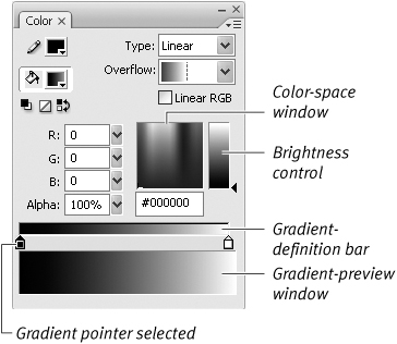
- For Overflow, leave the default setting, Extend (on the Mac the Overflow menu setting is labeled Extend; in Windows, the menu is iconic and the Extend setting appears as a black-to-white gradient).
Overflow determines how gradient colors fill a shape when you resize the gradient to be narrower than the shape it fills (to learn about resizing gradients, see Chapter 4).
- To add a new color to the gradient, do the following:
• Position the mouse pointer on or below the gradient-definition bar.
Flash adds a plus sign to the pointer, indicating that you can add a new gradient pointer in this area.
• Click anywhere along the gradient-definition bar.
Flash adds a new gradient pointer.
- To change the color of a gradient pointer, click it to select it, and define a new color using any of the methods described in the preceding section.
Double-click the gradient pointer to open a pop-up swatch set, and do one of the following:
• Click a swatch to copy the swatch color.
• Click an item on the desktop to copy its color.
• Enter a new value in the Hex field.
• Click the Color Picker button in the upper-right corner of the pop-up swatch set to access the System Color Picker for assigning new colors.
- To remove a color from the gradient, drag its pointer downward, away from the gradient-definition bar. The pointer disappears as you drag. The gradient preview changes to blend the colors in the remaining gradient pointers.
- Repeat steps 4 through 6 to create the colors you want in your gradient.
You can add up to 13 pointers (for a total of 15 colors) to a gradient.
- Drag the pointers to position them on the gradient-definition bar (Figure 2.10).
Figure 2.10. Choose a color for each gradient pointer. The colors and positions of the pointers on the bar define a gradient’s color transitions. Place pointers closer together to make the transition between colors more abrupt; place them farther apart to spread the transition out over more space.
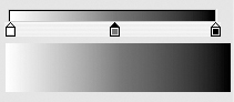
Gradient starts with white and blends first to gray and then to black

Move pointers in to increase width of outside bands

Click to add pointers
As you modify the gradient, your changes appear in all the Color controls for strokes or fills, depending on whether you assigned the gradient to strokes or fills.
- Open the Color panel.
- From the Type menu, choose Radial.
The tools for defining circular gradients appear. The gradient-definition bar looks the same as it does for linear gradients, but the preview shows your gradient as a set of concentric circles (Figure 2.11). The leftmost pointer defines the inner ring; the rightmost pointer defines the outer ring.
Figure 2.11. Choose Radial from the Type menu to create a circular gradient. The preview window translates the horizontal gradient-definition bar into the appropriate circular color transitions.
- Follow steps 3–8 of the previous task, “To create a linear gradient,” to define the color transitions in the radial gradient.
Tips
• To modify an existing gradient, choose it in the Swatches panel. Flash switches the Color panel to gradient mode and displays the selected gradient. Now you can make any changes you need.
• Gradients can have transparency. You simply use a transparent color in one or more gradient pointers (see “To define a color’s transparency,” earlier in this chapter). If a gradient has transparency, a grid shows up in the gradient pointer, in the Fill Color or Stroke Color control, and in the transparent part of the gradient in the preview window (Figure 2.12).
Figure 2.12. When transparent colors make up part of a gradient, grid lines appear in the gradient pointer, the Fill Color or Stroke Color control, and the gradient-preview window.

• Each pointer in a gradient can have a different alpha setting. To create fade effects, try creating a gradient that blends from a fully opaque color to a transparent one.
Working with Swatches
You can save a new color or gradient for the duration of your work session by adding the color currently displayed in the Color panel to the Swatches panel. The Fill Color and Stroke Color controls found in the Tools panel, in the Properties tab of the Property inspector, and in the Color panel also give you quick access to the current set of swatches..
To add a color or gradient to the Swatches panel:
- Create a new color or gradient using any of the techniques outlined in the preceding sections.
- In the Color panel, do either of the following:
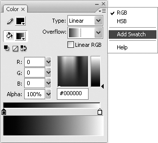
• From the options menu, choose Add Swatch (Figure 2.13).
Figure 2.13. The options menu in the Color panel has a command for adding the current color to the Swatches panel.
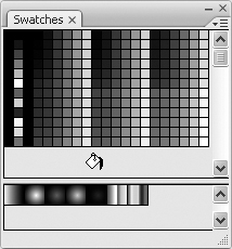
• Position the pointer over the blank area of the Swatches panel; when the paint-bucket pointer appears, click.
Flash adds the new solid color or gradient to the appropriate section of the Swatches panel (Figure 2.14).
Figure 2.14. Positioning the pointer over a blank spot in the Swatches panel changes the pointer to a paint bucket. Click to add whatever color is currently specified in the Color panel. Solid color swatches are added to the upper half of the Swatches panel; gradient swatches, to the lower half.
Tips
• You can add new colors to the Swatches panel even if it’s closed. But if you want to get feedback when you add a swatch, open the Swatches panel. Resize the panel window so that a bit of space appears below the existing swatches.
• To remove a swatch from the Swatches panel, select a swatch, and from the panel’s options menu, choose Delete Swatch.
• If the swatches in the Swatches panel are too small for you, resize the panel. The swatches grow bigger as the window widens.
Creating Color Sets
Flash stores a default set of colors and gradients in the system color file, but it stores the colors and gradients used in each document with that document. Flash lets you define what colors and gradients make up the default set. In addition, you can create and save other color sets and load them into the Swatches panel. This practice makes it easy to maintain a consistent color palette when you’re creating several documents for use in a single movie or on a single Web site.
To define a new set of colors:
- Define the colors and gradients for your color set (see “Creating Solid Colors and Gradients,” earlier in this chapter).
You don’t need to define them all at once, but after you have a set you want to save, go to step 2.
- Access the Swatches panel.
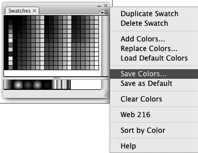
- From the panel’s options menu, choose Save Colors (Figure 2.15).
Figure 2.15. The options menu in the Swatches panel offers commands for working with color sets.
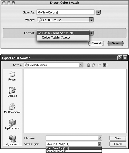
The Export Color Swatch dialog appears (Figure 2.16).
Figure 2.16. To save a set of colors for reuse, in the Export Color Swatch dialog, choose Flash Color Set from the Format menu (Mac, top) or Save As Type menu (Windows, bottom).
- Navigate to the folder where you want to store your color set.
- Enter a name for the color set in the Save As (Mac) or File Name (Windows) field.
- From the Format (Mac) or Save As Type (Windows) pop-up menu, choose one of two formats:
• To save colors and gradients in Flash’s proprietary Flash Color Set (CLR) format, choose Flash Color Set.
• To save the colors in Color Table (ACT) format, choose Color Table.
The ACT format saves only colors (not gradients) but lets you share color sets with other programs, such as Adobe Fireworks.
- Click Save.
Tip
• The options menu in the Swatches panel also offers some handy shortcuts for dealing with color sets. To reload the default color set, choose Load Default Colors. To remove all color swatches from the current panel window, choose Clear Colors. To load the standard Web-safe colors, choose Web 216. To arrange colors by hue, choose Sort by Color. (Note that you can’t undo the color sorting. Be sure to save your current set of colors if there’s any chance that you’ll want to restore the unsorted order.)
- From the options menu in the Swatches panel, choose either of the following:
• To add to the color set currently displayed in the Swatches panel, choose Add Colors.
• To replace the entire set currently displayed in the Swatches panel, choose Replace Colors.
The Import Color Swatch dialog appears (Figure 2.17).
Figure 2.17. To reload a saved set of colors, in the Import Color Swatch dialog, choose Flash Color Set from the Enable menu (Mac, top) or Files of Type menu (Windows, bottom).
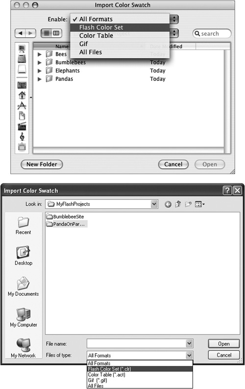
- To determine what types of files to display, from the Enable pop-up menu (Mac) or Files of Type (Windows) pop-up menu, choose one of the following:
• All Formats, which displays CLR, ACT, and GIF files
• Flash Color Set, which displays only CLR files
• Color Table, which displays only ACT files
• GIF, which displays only GIF files
• All Files, which displays files of any format
Note that the Color Table and GIF formats are for color import only; these formats don’t handle gradients. Flash Color Set handles both colors and gradients.
- Navigate to the file you want to import.
- Click Open.
Setting Fill Attributes
Flash offers five fill types: none, solid, linear gradient, radial gradient, and bitmap. You can create new fill colors and gradients in the Color panel (see “Creating Solid Colors and Gradients,” earlier in this chapter). To assign colors or gradients to selected tools or graphic elements, you can use the Color panel; the Tools panel; or any fill-related Property inspectors, such as the one that accompanies the rectangle tool.
To assign fill colors from the Tools panel:
- In the Tools panel, click directly on the color chip in the Fill Color control (the one identified by a paint-bucket icon).
The Fill Color control highlights, the pointer changes to an eyedropper, and a set of swatches pops up (Figure 2.18).
Figure 2.18. To set the fill color from the Tools panel, click the color chip in the Fill Color control. A set of swatches opens and you can choose the new fill color.

- To assign a new fill color or gradient, do one of the following:
• To assign a gradient, select one of the linear or radial gradient swatches.
• To select a solid color, click a solid swatch or an item on the Stage; the color directly below the tip of the eyedropper becomes the assigned fill color.
• To define a new fill color, enter hex values in the field above the swatches.
• To define transparency for the current fill color, enter a percentage less than 100 in the Alpha field and press Enter. Note, gradient fills do not have the transparency option in this control as transparency is a part of the gradient definition.
The new color appears in all Fill Color controls (in the Tools panel, the Properties tab of the Property inspector, and the Color panel) and will be used by any of the tools that create fills.
To assign fill colors from the Properties tab of the Property inspector:
- Access the Properties tab of the Property inspector.
- In the Tools panel, select one of the tools that creates fills.
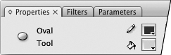
The rectangle, oval, rectangle-primitive, oval-primitive, polystar, brush, and paint-bucket tools all create fills. When one of these tools is selected, the Properties tab of the Property inspector displays a Fill Color control (Figure 2.19).
Figure 2.19. When nothing is selected on the Stage and you select a tool that creates fills, such as the oval tool, the Properties tab of the Property inspector displays a Fill Color control.
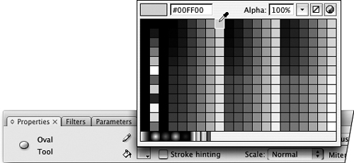
- In the Properties tab of the Property inspector, click directly on the color chip in the Fill Color control (the one identified by a paint-bucket icon).
The current set of swatches appears (Figure 2.20).
Figure 2.20. The color controls on the Property inspector work just like those in the Tools and Color panels. Click the color chip to access a set of color swatches.
- To assign a new fill color, follow the instructions in step 2 of the preceding task.
Tip
• To access a System Color Picker for assigning fill colors, click the color chip in one of the Fill Color controls and then click the Color Picker button from the pop-up swatch window (Figure 2.21).
Figure 2.21. Click the Color Picker button to access the system’s color picker(s) for defining a color that’s not in the current swatch set.

Setting Stroke Attributes
A line has three main attributes: color, thickness (also known as weight or, in Flash, stroke height), and style. You set all three in the Properties tab of the Property inspector for any tool that creates strokes. The Properties tab of the Property inspector also lets you control the way the ends of lines (caps) look and the way lines connect (joins).
- With the Properties tab of the Property inspector open, in the Tools panel, choose a tool that creates strokes (the pen, line, rectangle, oval, rectangle-primitive, oval-primitive, polystar, pencil, and ink-bottle tools all create strokes).
The Properties tab of the Property inspector for the selected tool appears, displaying the current settings for strokes.
- To select a stroke color, do the following:
• In the Properties tab of the Property inspector (or in the Tools panel), click the Stroke Color control.
The pointer changes to an eyedropper, and a set of swatches appears (Figure 2.22).
Figure 2.22. Clicking the Stroke Color control in the Properties tab of the Property inspector opens a set of color swatches and provides an eyedropper pointer for selecting a new color.
• Click the swatch with the desired color.
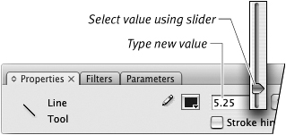
- To set the stroke’s weight, in the stroke-height field, enter a number between 0.25 and 200, or drag the slider next to the field (Figure 2.23).
Figure 2.23. Entering a new value in the stroke-height field sets the weight, or thickness, for strokes created by tools that draw strokes.
- To set the stroke’s style, select a style from the stroke-style pop-up menu (Figure 2.24).
Figure 2.24. Choose a stroke style from the pop-up menu in the Properties tab of the Property inspector.
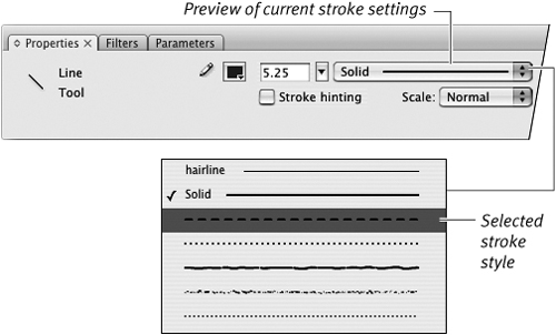
There are seven styles to choose from: hairline, solid, dashed, dotted, ragged, stippled, and hatched.
A graphic representation of your selected style appears in the stroke-style menu.
- To set the way a solid or hairline stroke ends, from the Cap pop-up menu, choose a cap style.
• None ends the stroke exactly where you stop drawing it.
• Round extends the stroke by half the current stroke height, creating a rounded end.
• Square extends the stroke by half the current stroke height, creating a square end (Figure 2.25).
Figure 2.25. Set a Cap style in the Properties tab of the Property inspector to control the look of the ends of lines. The None option keeps the line’s original length and makes the end flat; Round extends and rounds the line’s end; and Square extends and squares off the end.
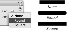
- To set the way solid or hairline strokes meet, click the Join pop-up menu.
• Miter creates a sharp corner.
• Round creates a slightly curved corner.
• Bevel creates a slightly flattened corner (Figure 2.26).
Figure 2.26. Set a join style in the Properties tab of the Property inspector to control the way lines connect. Miter makes a clean pointed corner, Round makes a rounded corner, and Bevel slices a flat piece off the corner. The Cap and Join options are available only when the stroke properties are set to Solid or Hairline.

Tips
• The Tools panel displays three buttons for setting basic stroke (and fill) colors quickly. Clicking the overlapping black and white squares sets the Stroke Color control to black (and the Fill Color control to white). Clicking the small squares with an arrow next to them makes the current stroke and fill colors change places. Clicking the square with the red line through it sets the currently selected color control (fill or stroke) to No Color.
• In Flash, the hairline setting is considered a stroke style, not a stroke height. (Use the stroke-style pop-up menu to get the hairline setting.) Hairlines in a symbol don’t change thickness when you resize the symbol. Other lines in a symbol grow thicker or thinner as you scale the symbol up or down. (To learn about symbols, see Chapter 7.)
• To constrain the way strokes scale in your published movie, with a stroke (or stroke-creating tool) selected, choose a setting from the Scale menu in the Properties tab of the Property inspector. In the default (Normal) mode, a 1-pixel stroke becomes a 2-pixel stroke if your final movie gets enlarged to 200 percent. To prevent a selected stroke from scaling at all, choose None. To allow the stroke to scale in one direction only, choose Horizontal or Vertical.
• Click the Stroke Hinting check box in the Properties tab of the Property inspector to ensure crisp lines in your final output. Without hinting, lines sometimes appear slightly blurry on some monitors.
• You can modify Flash’s stroke styles. You might, for example, want larger dots in the dotted line or bigger spaces in the dashed line. Select a stroke-creating tool; in the Properties tab of the Property inspector, select the stroke style you want to modify, and then click the Custom button. The Stroke Style dialog appears, in which you can assign new settings. Click OK to close the dialog and confirm the settings. Those settings continue in force for that style until you change them or end the work session.
• You can also set stroke color from any Stroke Color control (in the Properties inspector, the Tools panel, or the Color panel). Click the Stroke Color control, and select a color as described in “Setting Fill Attributes,” earlier in this chapter.
• You can set the Join property for rectangles created with the rectangle-primitive tool, but you’ll only see the joins on sharp corners (those with a corner radius setting of 0).
Merge Drawing vs. Object Drawing vs. Primitive-Shapes
Flash CS3 creates three types of graphic objects: merge-shapes (also called raw shapes), drawing objects, and primitive-shapes. You can use most of the drawing tools to create merge-shapes or drawing objects simply by selecting the appropriate drawing mode. To create primitives, you must select either the rectangle-primitive or oval-primitive tool.
In Merge Drawing mode, the strokes and fills you create are raw shapes and are ready for editing directly on the Stage; raw shapes on a single layer interact with one another, dividing and replacing strokes and fills that overlap or intersect (you’ll learn more about how shapes interact in Chapter 5).
In Object Drawing mode, the strokes and fills you create are still directly editable on the Stage, but they don’t interact with other shapes on the same layer. Shapes created in Object Drawing mode act somewhat as if they were isolated on a separate layer or protected using the Group command (you’ll learn more about working with grouped shapes in Chapter 5 and about shapes on separate layers in Chapter 6). But shapes created in Object Drawing mode can be modified directly on the Stage (see Chapter 4), whereas grouped objects generally can’t.
Primitive-shapes—those created with the rectangle-primitive and oval-primitive tools—do not interact with other shapes on the same layer. Behind the scenes, Flash creates these shapes in Object Drawing mode but locks and constrains them so that they always exhibit certain defining characteristics. Those characteristics are editable and appear as properties in the Property inspector when you select a primitive tool in the Tools panel or a primitive-shape on the Stage. You can edit these properties of a primitive anytime, but you can’t freely edit a primitive the way you can edit a shape created in Merge/Object Drawing mode. For example, you can change the inner radius setting for on oval-primitive to transform a solid oval to a donut shape, but you can’t edit an oval-primitive’s outline to give it pointy ends and transform it into a football shape.
Flash’s default mode for drawing tools is Merge Drawing. To turn on Object Drawing mode, select a tool that creates strokes and/or fills, and then click the Object Drawing button in the Tools panel (Figure 2.27). Once you activate Object Drawing mode for any tool, all tools that create strokes and fills are set to Object Drawing mode. To return to Merge Drawing mode, you must click the Object Drawing button again to deselect Object Drawing mode (or press J on the keyboard to toggle between Merge Drawing and Object Drawing). Whichever Merge/Object Drawing setting is active when you end a work session will be active the next time you open Flash. The Merge/Object Drawing mode button is absent from the Tools panel when you choose one of the primitive tools (Figure 2.28).
Figure 2.27. You can set the drawing tools to create shapes that don’t interact with other shapes on the same layer. Select Object Drawing mode in the Tools panel.
![]()
Figure 2.28. The drawing-mode button does not appear in the Tools panel when you select the oval-primitive or rectangle-primitive tool.

For many tasks, you’ll see no difference between working with the three types of shapes; in some tasks, however, the difference is crucial. For the exercises in this book, unless otherwise noted, you can create shapes using either drawing mode or using the primitive-shape tools.
Making Geometric Shapes
Flash provides separate tools for drawing ovals, rectangles, and polygons or stars. The tools work similarly; all can draw a shape as an outline (just a stroke) or as a solid object (a fill). You can also create a geometric shape with a fill and a stroke simultaneously. There are special properties that define rectangles and ovals that you can set as precise values in the Property inspector.
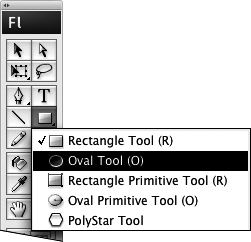
- To select a geometric-shape tool, do the following:
• In the Tools panel, click the active geometric-shape tool.
• From the submenu that appears, choose a tool—for example, the oval tool (Figure 2.29).
Figure 2.29. The Tools panel combines all the geometric-shape tools under a pop-up submenu. To view them all, click the geometric-shape tool that’s visible, then click a tool to select it and close the submenu.
- In the Property inspector, enter values and choose settings for the properties you wish to control.
When creating an outline shape, you may want to select new properties for the stroke’s color, height, and style (see “Setting Stroke Attributes,” earlier in this chapter). There are also specific oval and rectangle properties that appear in the Property inspector when you select the rectangle, rectangle-primitive, oval, and oval-primitive tools.
- To set the tool to create an outline with no fill, in the Tools panel, do the following:
• Click the paint-bucket icon of the Fill Color control; Flash highlights Fill Color as the active control.
• Click the No Color button (Figure 2.30).
Figure 2.30. When the Fill Color control is selected in the Tools panel, selecting the No Color button allows whatever tool you select to create a shape with no fill.

- Move the pointer over the Stage.
The pointer turns into a crosshair.
- Click and drag to create the geometric shape (Figure 2.31).
Figure 2.31. With a geometric-shape tool selected, click the Stage and drag to create an outline preview of a shape (top). Release the mouse button, and Flash creates a shape using the current settings for fills and strokes. In this case, the oval tool is set to black stroke color, no fill, dashed stroke style, and a stroke height of 1 point (bottom).
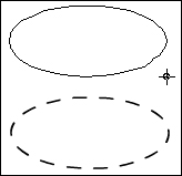
Flash previews the shape as you drag.
- Release the mouse button.
Flash draws an outline.
Tips
• To draw a perfect circle (or square), hold down the Shift key while you draw with the rectangle, oval, rectangle-primitive, or oval-primitive tool.
• To make ovals (or rectangles) grow outward from the center point as you draw, position the pointer where you want the center of the shape to be; hold down the Option key (Mac) or Alt key (Windows) as you drag. Shapes drawn with the polystar tool always grow from the center.
- To select a geometric-shape tool follow steps 1 and 2 in the preceding exercise.
For this task, for example, select the rectangle tool.
- To set the tool to create just a fill with no outline, in the Tools panel, do the following:
• Click the pencil icon of the Stroke Color control; Flash highlights Stroke Color as the active control.
• Click the No Color button (Figure 2.32).
Figure 2.32. To create a geometric shape that’s just a fill (no outlining stroke), in the Tools panel, select the Stroke Color control and click the No Color button.
- Follow steps 4 through 6 in the preceding exercise.
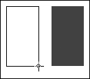
Flash draws a geometric fill, using the currently selected fill color (Figure 2.33).
Figure 2.33. As you drag the rectangle tool, Flash creates an outline preview of a rectangle (left). To complete the fill shape, release the mouse button (right).
Tip
• You can create polygons and star shapes with the polystar tool (choose it from the geometric-shape tool’s submenu in the Tools panel). To set the number of sides in the polygon and to switch from polygons to stars, select the polystar tool and click the Options button in the Polystar Tool Properties tab of the Property inspector. The Tool Settings dialog appears. Enter values for the number of sides and how sharp the star points are, then click OK.
- In the Tools panel, select the rectangle or rectangle-primitive tool.
The Property inspector displays the tab for the selected tool (Figure 2.34).
Figure 2.34. When you select the rectangle or rectangle-primitive tool, the Property inspector displays special properties for defining a rectangle. The properties are the same for both tools.

- To create a rectangle with four identical corners, set the Constrain Corner Radius button to the locked state (Figure 2.35).
Figure 2.35. By default, the rectangle and rectangle-primitive tools create shapes whose corners all have the same radius. When the closed-lock icon appears, there is just one field for entering values and the settings are constrained.

Clicking the lock icon toggles between the unconstrained (open-lock icon) and constrained (closed-lock icon) states.
- To create a rectangle with rounded corners, in the Rectangle Corner Radius field enter a positive number.
or
To create a rectangle with indented corners, in the Rectangle Corner Radius field enter a negative number.
- In the Tools panel, select the oval (or oval-primitive) tool.
The Property inspector displays the tab for the selected tool (Figure 2.36). The properties are the same for both tools.
Figure 2.36. When you select the oval or oval-primitive tool, the Property inspector displays special properties for defining an oval. The properties are the same for both tools.

- To create variations on the oval shape, in the Oval (Primitive) Tool tab of the Property inspector, do any of the following:
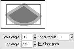
• To create pie-wedge shapes, in the Start Angle and/or End Angle field, enter a number from 0 to 360 (Figure 2.37).
Figure 2.37. Entering values in the Start Angle and End Angle fields creates partial ovals like those often used in pie charts. Click the triangle to the right of the field to open a circular slider for entering values.

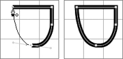
• To create open arcs, deselect the Close Path check box. When you create pie-wedge shapes, this setting creates an open path. Flash removes the shape’s fill (if one is present) and deletes the straight line segments from the wedge shape (Figure 2.38).
Figure 2.38. Deselecting the Close Path check box lets you create arcs out of pie-wedge oval shapes. If the shape has an inner-radius setting greater than 0, in its open-path form, it appears as two arcs.
Shape with closed path

Shape with open path
• To create ovals with hollow centers, in the Inner Radius field, enter a number from 0 to 99.
Flash draws a hollow oval inside the first (Figure 2.39). The inner-radius setting corresponds to the percentage of the outer oval’s “fill” that gets removed by the inside oval. (The outer oval may have a fill of No Color, in which case the inner oval just appears as an outline.)
Figure 2.39. Entering a number greater than 0 in the Inner Radius field creates an oval with a hollow center.

Tip
• You can change an oval-primitive’s start- or end-angle settings interactively. Select the shape on the Stage. In the Property inspector, click the triangle to the right of the Start Angle or End Angle field, and a circular slider appears. Click anywhere on the slider or drag the control point to change the setting; the shape on the Stage changes interactively. Press enter or click away from the slider to confirm the new value.
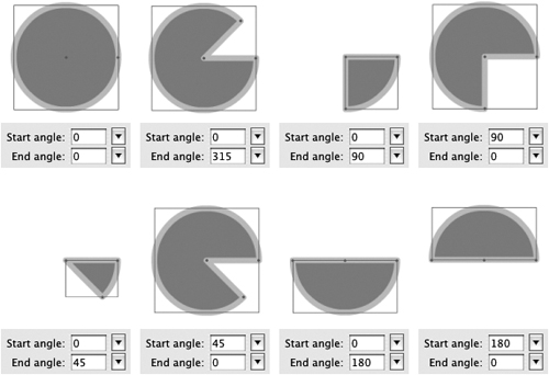
The Oval (Primitive) Tool tab of the Property inspector offers controls for start angle and end angle; the angle settings let you create pie-wedge shapes but can be a bit difficult to interpret at first. Imagine drawing a circle on the face of an analog clock. The start angle is the point where you put your pencil down to begin drawing; the end angle is the point where you lift the pencil and stop drawing. (When Flash creates oval-primitives on the Stage, it turns the start and end angles into control points that you can drag to modify the beginning and ending of the oval’s outline.) The values you enter into the Start Angle and End Angle fields correlate to degrees of a circle. The value 0 corresponds to 3 o’clock, 90 to 6 o’clock, 180 to 9 o’clock, and so on; Flash draws clockwise when creating oval-primitives. When the start and end angle have the same value, both control points sit on the same spot, and the circle is complete. When the values differ, there’s a gap in the circle. When you set the oval-primitive to be a closed path, Flash finishes the shape by drawing straight-line segments to the center of the oval, creating a pie-wedge. If the oval has an inner-radius value greater than 0, the segments connect with the inner oval, creating a C shape or a partial C shape (Figure 2.40). To get a feel for how this works, create an oval-primitive on Stage, then select it, and experiment with the various options in the Property inspector. Use the interactive start- and end-angle controls to see the relationship of angles to the clock face example above. Experiment with the inner radius and close-path settings as well.
Figure 2.40. By changing the Start Angle and End Angle values in the Oval (Primitive) Tool tab of the Property inspector, you set the oval or oval-primitive tool to create partial circles and pie wedges.
Creating Free-form Shapes
Flash offers three tools for creating free-form shapes: the pencil, pen, and brush. The pencil and pen tools create stroke outlines, and the brush tool creates fills without strokes. The pencil and pen tools create only outlines, even if you draw a closed shape. Once you’ve created a shape, you can always modify it—say, to fill an empty outline or add an outline to a plain fill shape.
The pencil tool lets you draw lines (strokes) naturally, as you would with a real-world pencil, but using the mouse or a graphics tablet and pen. Flash hides information about the anchor points and curves of a stroke drawn with the pencil. With the pen tool, you place anchor points and adjust Bézier curves to create strokes. You can use the pen tool not only to create Bézier curves initially, but also to modify them once they are on the Stage. In addition there are three anchor-point tools for modifying Bézier curves on the Stage—the add-anchor-point tool, the delete-anchor-point tool, and the convert-anchor-point tool. In this chapter, you’ll use the pen tool to create free-form shapes; in Chapter 4, you’ll learn to use the pen tool and the anchor-point tools to modify shapes.
For the tasks below, make sure the grid is visible (see Chapter 1) and set drawing preferences as follows: choose Flash > Preferences (Mac) or Edit > Preferences (Windows) to open the Preferences dialog; choose Drawing from the Category list, and select the Show Pen Preview and Show Solid Points check boxes; leave the other items at their default settings.
To draw free-form strokes with the pencil tool:
- In the Tools panel, select the pencil tool, or press Y.
- From the Pencil Mode menu (Figure 2.41), choose one of the following assistance modes:
Straighten resolves minor variations into straight-line segments.
Smooth resolves minor variations into smooth curves.
Ink provides very little assistance, leaving minor variations.
Figure 2.41. When the pencil tool is selected, the Tools panel displays a pop-up menu of pencil modes.

- Move the pointer over the Stage.
The pointer changes to a pencil icon.
- Click, and draw a squiggle.
Flash previews your rough line.
- Release the mouse button.
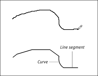
Flash recasts the line you’ve drawn according to the assistance mode you chose in step 2, creating a set of straight-line segments and regular curves (Figure 2.42).
Figure 2.42. With the pencil in Straighten mode, when you draw a squiggle, Flash previews it for you. When you release the mouse button, Flash applies straightening, turning your rough squiggle (top) into a set of straight-line segments and smooth curves (bottom).
Tip
• You can apply smoothing and straightening (even shape recognition) after you’ve drawn an outline or shape by selecting it on the Stage and then clicking the Straighten or Smooth modifier of the Selection tool (you’ll learn more about making and modifying selections in Chapter 4).
To draw free-form strokes with the pen tool:
- In the Tools panel, select the pen tool; or press P, =, -, or C (Figure 2.43).
Figure 2.43. Select the pen tool to create paths.

- Set the stroke attributes for your path.
- Move the pointer over the Stage.
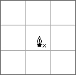
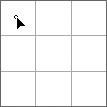
The pen tool appears with a small x next to it (Figure 2.44). The x indicates that you’re ready to place the first point of a path.
Figure 2.44. The x next to the pen tool indicates that you’re about to start a new path. Click to place the first anchor point.
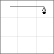
- Click where you want your line segment to begin.
The pointer changes to a solid arrowhead; a small hollow circle indicates the location of the anchor point on the Stage.
- Reposition the pen tool where you want your line segment to end.
Flash extends a preview of the line segment from the first point to the tip of the pen as you move around the Stage.
- Click.
Flash completes the line segment using the selected stroke attributes. The anchor points appear as solid squares (Figure 2.45).
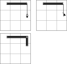
Figure 2.45. Flash previews points as you place them (top), and it adds a stroke to the path as soon as you complete a segment (bottom).
First point previewed
Preview line segment

Click to place second point

Completed line segment
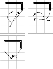
- To add a straight segment to your line, click the Stage where you want the segment to end, and release the mouse button (Figure 2.46).
Figure 2.46. Continue clicking to add segments to your free-form shape. A quick click (top) adds a straight line segment (bottom).
- To add a curve segment, click the Stage where you want the curve segment to end, and then drag the pointer.
Flash places a preview point on the Stage, the pointer changes to a solid arrowhead, and Bézier handles (sometimes referred to as tangent handles) appear (Figure 2.47).
Figure 2.47. Click and drag to create a curve point; as you drag, the point’s Bézier handles activate. The bulge of the curve grows away from the direction of your drag. For example, to make the curve bulge upward, drag downward.

- Drag the pointer in the opposite direction from which you want your curve to bulge.
The Bézier handles extend from the anchor point, growing in opposite directions as you drag. Flash previews the curve you’re drawing (Figure 2.48).
Figure 2.48. To make the curve bulge downward, drag upward. Dragging the handles out further deepens the curve.
- Still keeping the mouse button down, drag the pointer to reposition the Bézier handle.
Dragging the handle clockwise or counterclockwise around its anchor point controls the direction of the bulge; dragging the handle farther from the anchor point deepens the curve (Figure 2.49).
Figure 2.49. Move the handles clockwise or counter-clockwise around the point to modify the curve shape (top). Drag the handles in or out to make the curve deeper or shallower (bottom).
- When the curve preview looks the way you want, release the mouse button.
Flash completes your curve segment with a stroke (Figure 2.50).
Figure 2.50. When you finish positioning handles for a segment and release the mouse button, Flash adds a stroke to the segment.

- To create an open path,
 -click (Mac) or Ctrl-click (Windows) the Stage.
or
To create a closed shape, do the following:
• Position the pointer over your first anchor point.
• Flash previews the closing segment of your shape. A small hollow circle appears next to the pen tool (Figure 2.51).
Figure 2.51. To create a closed shape, position the pointer over the first anchor point you placed. When you see the hollow-circle icon, click that first point (left). Flash adds the finishing segment, creating a closed path (right).
• Click the first anchor point.
• Flash closes the shape, adding a stroke to the path.
Once the path is complete, the pen tool pointer displays a small x, indicating that the tool is ready to place the first anchor point of a new path.
Tips
• There are other ways to end open paths. Choose Edit > Deselect All, or press ![]() -Shift-A (Mac) or Ctrl-Shift-A (Windows). In the Tools panel, click a different tool. You can also double-click the last point you placed. To use this technique you must be drawing a path that ends with a straight-line segment that doesn’t involve Bézier handles.
-Shift-A (Mac) or Ctrl-Shift-A (Windows). In the Tools panel, click a different tool. You can also double-click the last point you placed. To use this technique you must be drawing a path that ends with a straight-line segment that doesn’t involve Bézier handles.
• In previous versions, Flash would automatically fill a shape drawn with the pen tool, using the current fill color. In Flash CS3, you must use the paint-bucket tool to add a fill to a closed shape drawn with the pen.
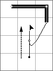
• The pen tool can add to a line created earlier (Figure 2.52). To extend outward from the original line, position the pointer over the end of the line (the terminal anchor point). A modifier—a small slash—appears next to the pen icon. Click the terminal anchor point and the pen links to that point as if you’d just placed it; continue adding segments as you learned to do in the previous exercises. You can also join to an existing line during the process of creating a new line. Click to place the anchor points of the new line, but don’t double-click to end the line. Instead, position the pointer over one of the terminal anchor points of the line you want to join. A modifier appears next to the pen icon; if you link to a merge-shape segment, the modifier is a small hollow circle; if you link to a drawing-object, the modifier is a chain-link icon. Click the existing terminal anchor point, and Flash joins the two lines.
Figure 2.52. You can use the pen tool to add to existing line segments. Position the pointer over the end point of the existing line and click (top), then continue clicking to place more points. Or, place new points first, then position the pointer over the end point of the line you want to join (bottom). When the modifier icon appears, click to join the lines.

Extend Line

Join Line
To create free-form solid fills with the brush tool:
- In the Tools panel, select the brush tool or press B (Figure 2.53).
Figure 2.53. The brush tool and its modifiers.

- To optimize the brush for a particular painting task, in the lower portion of the Tools panel, select any of the following:
• From the Brush Size pop-up menu, choose a size for the brush tip.
• From the Brush Shape pop-up menu, choose a shape for the brush tip.
• From the Brush Mode pop-up menu, choose a painting mode; for this exercise, choose Paint Normal (Figure 2.54). The painting modes let you control how brushstroke fills act when you use the brush tool to paint over other shapes.
Figure 2.54. The Brush Mode options give you control over how fills created with the brush tool interact with other shapes on the same layer. Choosing Paint Normal lets you paint mergeshape fills that act like any other fills when they overlap other shapes.

Overlapping shapes interact in different ways depending on whether they are merge-shapes, drawing-objects, or primitives. (You’ll learn about how overlapping shapes interact in Chapter 5.)
• To paint brushstroke fills that vary in thickness, choose Use Pressure. This option appears only when a graphics tablet is connected to your computer.
- Select or define a solid fill color using any of the techniques outlined earlier in this chapter.
- Move the pointer over the Stage.
The pointer changes to reflect the current brush size and shape.
- Click and draw on the Stage.
Flash previews your brushwork in the currently selected fill (Figure 2.55).
Figure 2.55. Drawing with the brush creates a preview of your shape (left); Flash recasts the shape as a vector graphic with the currently selected fill color and smoothing settings (right).

- When you complete your shape, release the mouse button.
Flash creates the final shape, smoothing it according to settings in the Property inspector (see the sidebar “The Mystery of Brush Smoothness Settings,” later in this chapter).
Tip
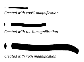
• You can change the size of your brushstroke by changing the magnification at which you view the Stage. To create a fat stroke without changing your brush-tip settings, set the Stage view to a small percentage. To switch to a thin stroke, zoom out to a higher percentage (Figure 2.56). Be sure to check your work in 100% view.
Figure 2.56. Flash created these three brushstrokes with exactly the same brush size—only the magnification level of the Stage was changed for each stroke.
Flash’s brush tool offers a way to create free-flowing swashes of color. These shapes are actually free-form fills drawn without a stroke. The brush tool lets you simulate artwork you’d create in the real world with a paintbrush or marking pen. A variety of brush sizes and tip shapes helps you create a painterly look in your drawings.
If you have a pressure-sensitive drawing tablet, the brush can interact with it to create lines of varying thickness, imitating the thick and thin lines of real-world brushwork. The more pressure you apply, the thicker the brushstroke (Figure 2.57).
Figure 2.57. Selecting the brush tool’s Use Pressure modifier activates the pressure-sensitive capabilities of a connected pressure-sensitive pen and graphics tablet. To produce lively lines of varying thickness, apply more or less pressure as you draw. Flash created all the lines in this cat with a single brush size and shape.

- Follow steps 1 and 2 in the preceding task.
- Using one of the methods described earlier in this chapter, select (or define) a linear or radial gradient fill.
- To lock or unlock the gradient, in the Tools panel, do either of the following:
• To paint shapes that contain the full gradient-spectrum, deselect Lock Fill (Figure 2.58).
Figure 2.58. Deselect the Lock Fill modifier to paint with an unlocked gradient.

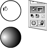
• To paint shapes that reveal just a portion of the gradient (as if the shape were a window onto a gradient that filled the whole Stage area), select Lock Fill.
- Paint with the brush as described in steps 4–6 in the preceding task.
Flash can’t preview the shape you paint with a gradient fill. The preview shape has a black-and-white pattern.
Flash redraws the painted shape, using the current lock-fill and fill-color settings (see the sidebar “The Mystery of Gradients and Flash’s Drawing Models,” later in this chapter).
For unlocked fills, the full gradient is visible in the shape (Figure 2.59).
Figure 2.59. A brushstroke shape painted with an unlocked linear-gradient fill (top) and one painted with radial-gradient fill (bottom).
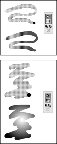
For locked fills, just a portion of the gradient is visible in the shape (Figure 2.60).
Figure 2.60. With the brush tool’s Lock Fill modifier deselected, each brushstroke fill you paint contains the full range of the current gradient (top); with Lock Fill selected, each brushstroke fill appears to reveal a section of a gradient that runs the width of the Stage and the Pasteboard (bottom).

Tips
• Try painting a variety of brushstrokes in both drawing modes; use locked and unlocked gradients; use different areas of the Stage; and make the shapes different lengths. Notice the way each shape displays the gradient.
• If the first gradient you paint in a work session has a locked fill, Flash puts the center of the underlying locked gradient along the left edge of the Stage. That means half the gradient lies on the Pasteboard, not on the Stage. To choose a different location for the center of a locked gradient, first use the brush tool to paint an unlocked gradient that’s centered the way you want. When you switch to painting with Lock Fill active, the underlying locked gradient aligns with the last unlocked gradient you painted. You can then delete the unneeded unlocked gradient, use the paint-bucket tool to change it to a locked gradient (see Chapter 4).
• After you’ve created a shape with a gradient fill, you can adjust the location of the center of the gradient by using the gradient-transform tool (see Chapter 4).
Adding Strokes and Fills
As you’ve learned earlier in this chapter, you can use the line, pencil, pen, and geometric-shape tools to create outline shapes—strokes without fills. To create fill shapes that have no stroke outline, you use the brush, pen, and geometric-shape tools. At any point you can add the missing element to such shapes. The ink-bottle tool adds strokes that outline plain fill shapes; the paint-bucket tool adds fills inside plain outline shapes. (You can also use these tools to modify strokes and fills; see Chapter 4.)
- On the Stage, draw a fill that has no stroke, or work with an existing unstroked shape.
For a merge-shape, make sure the fill is deselected; for a drawing-object, the fill can be selected or deselected.
- In the Tools panel, select the ink-bottle tool or press S (Figure 2.61).
Figure 2.61. The ink-bottle tool applies all the stroke attributes currently set in the (Ink Bottle Tool) Properties tab of the Property inspector.
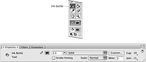
- In the Ink Bottle Tool Properties tab of the Property inspector, set the desired stroke attributes (see “Setting Stroke Attributes,” earlier in this chapter).
- Position the pointer over a fill shape that has no stroke.
The pointer appears as a little ink bottle, spilling ink.
- With the ink bottle’s hot spot, click a fill shape in one of the following ways:
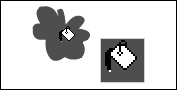
• To add a stroke around the outside of your shape, click near the outside edge of the shape (Figure 2.62).
Figure 2.62. As you move the ink bottle over a filled shape, the hot spot appears as a white dot at the end of the ink drip that’s spilling out of the bottle. To add a stroke around the outside edge of your fill shape, position the hot spot along that edge (top) and then click. Flash adds a stroke with the current attributes set in the (Ink Bottle Tool) Properties tab of the Property inspector (bottom).

Before

After
• To add a stroke around the inside of a shape that has a hole cut out of it, click near the inside edge of the shape.
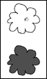
• To outline both the outside of a shape and the hole inside the shape, click in the middle of the shape (Figure 2.63).
Figure 2.63. Position the ink bottle’s hot spot in the middle of your fill shape (top), and then click. Flash uses the current stroke attributes to add a stroke around the outside and inside of your shape (bottom).

Before

After
Flash adds strokes to the outside edge, inside edge, or both, using the Properties tab of the Property inspector’s current settings for color, thickness, and style.
Tips
• Flash lets you use gradients for strokes. In step 3 of the preceding task, in the Properties tab of the Property inspector, choose a linear or radial gradient from the Stroke Color control’s pop-up swatch set. Why might you want a gradient stroke? For an oval shape, adding a thick stroke with a radial gradient can help create the illusion of 3D depth or make the shape appear to glow.
• Another way to “add” missing strokes to drawing-objects and primitive-shapes is to modify them using the Property inspector. First select the drawing-object or primitive on the Stage. Then change the stroke properties, including color, in the Property inspector. You can use this technique to add strokes to multiple drawing-objects and/or primitives (the technique doesn’t work for merge-shapes, however). You’ll learn more about modifying graphic objects in Chapter 4.
To fill an outline shape with solid color:
- On the Stage, draw an outline stroke that has no fill, or work with an existing outline shape.
The outline can be selected or deselected.
- In the Tools panel, select the paint-bucket tool, or press K (Figure 2.64).
Figure 2.64. The paint-bucket tool and its modifiers.

- From the Gap Size menu in the Tools panel, choose the amount of assistance you want (Figure 2.65).
Figure 2.65. The Gap Size menu controls Flash’s capability to fill shapes that aren’t fully closed.
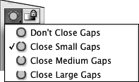
If you draw your shapes precisely, medium or small gap closure serves you best; you don’t want Flash to fill areas that aren’t meant to be shapes. If your drawings are rougher, choose Close Large Gaps. This setting enables Flash to recognize less-complete shapes.
- From any Fill Color control, select a solid fill color.
- Place the paint bucket’s hot spot (the tip of the drip of paint) inside the outline shape (Figure 2.66).
Figure 2.66. The hot spot on the paint-bucket tool is the little drip at the end of the spilling paint. The hot spot changes to white when you move the paint bucket over a darker color.
- Click.
The shape fills with the currently selected fill color (Figure 2.67).
Figure 2.67. Clicking inside an outline shape with the paint bucket (top) fills the shape with the currently selected fill color (bottom).
Tips
• You may be unaware that your shape has any gaps. If nothing happens when you click inside a shape with the paint bucket, try changing the Gap Size setting in step 3.
• Gap-closure settings are relative to the amount of magnification you’re using to view the Stage. If the paint bucket’s largest gap-closure setting fails at your current magnification, try again after reducing magnification (Figure 2.68).
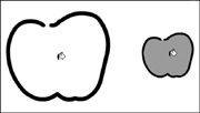
Figure 2.68. The paint bucket can’t fill this apple shape with the setting of Close Large Gaps and a magnification of 100 percent (left). But in a 50 percent view, the paint bucket with the same large-gap closure setting recognizes this shape as complete and fills it.
• Another way to “add” missing fills to drawing-objects and primitives is to modify them using any Fill Color control. First select the outline drawing-object or primitive on the Stage. Then choose a color from the Fill Color control in the Tools, Color, or Property inspector panel. You can use this technique to add fills to multiple drawing-objects and/or primitives (the technique doesn’t work for outline merge-shapes, however). You’ll learn more about modifying graphic objects in Chapter 4.
To fill outline shapes with unlocked gradients:
- In the Tools panel, select the paint-bucket tool.
- In the Color panel, define a new gradient (see “Creating Solid Colors and Gradients,” earlier in this chapter),
or
From any Fill Color control, select an existing linear or radial gradient (see “Setting Fill Attributes,” earlier in this chapter).
- In the Tools panel, make sure that Lock Fill is deselected (Figure 2.69).
Figure 2.69. Deselect the Lock Fill button to fill a shape with an unlocked gradient.
- Follow steps 5 and 6 in the preceding task.
Each outline shape you click fills with the gradient currently displayed in the Fill Color control. If you chose a linear gradient in step 2, Flash centers the unlocked gradient within the outline shape (Figure 2.70). If you chose a radial gradient, the location you click with the paint bucket’s hot spot determines where the center of the unlocked gradient appears (Figure 2.71).
Figure 2.70. You can use the paint-bucket tool to apply a linear-gradient fill. An unlocked gradient is centered within the outline shape’s bounding box.
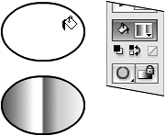
Figure 2.71. The paint-bucket tool can also apply a radial-gradient fill. Click where you want to locate the center of the gradient.
To fill outline shapes with locked gradients:
- Follow steps 1 and 2 in the preceding task.
- In the Tools panel, select the Lock Fill button.
- Follow steps 5 and 6 in “To fill an outline shape with solid color,” earlier in this section.
Each outline shape you click fills with a portion of the gradient currently set in the Fill Color control (see the sidebar “The Mystery of Gradients and Flash’s Drawing Models,” earlier in this chapter).