Simulating Microcontrollers
4.1 INTRODUCTION TO MULTISIM MCU
Multisim MCU is an add-on to Multisim that enables the user to build and simulate circuits based on microcontroller units. The letters MCU stand for Microcontroller Unit Co-Simulation for SPICE-Based Circuits
Microcontroller circuits are capable of handling several tasks (reading/writing data to a memory, interfacing sensors, acquiring real world signals, etc.) based on a program written by the user. Multisim MCU can simulate the behavior of a microcontroller running custom code.
The advantages of programming and testing in a simulated environment are numerous. One of the main benefits of this approach is the ability to run and debug microcontroller circuits interacting with electronic components. This is something that most debuggers fail to deliver.
4.2 MULTISIM MCU BASICS
In Multisim the procedure for working with microcontrollers is slightly different to the procedure for dealing with electric or electronic circuits directly.
The first requisite to be covered is to have already installed the MCU module. This module is part of the student version and it is responsible of providing the appropriate environment for microcontroller simulation.
In the physical world a microcontroller is usually programmed using dedicated hardware. Sometimes this hardware is programmed using an RS232 or USB programmer. Nowadays, even Bluetooth programmers can be used. The main function of the programmer is to transfer a .hex file (the .hex extension comes from hexadecimal because the source file is in binary/hexadecimal format) to the microcontroller. In order to do this, some considerations apply like holding the reset line at a low level and use the appropriate signal level (commonly TTL levels used are 0 and 5 VDC).
This binary/hexadecimal file is obtained after having compiled and linked the source code. This task is accomplished by the compiler. The compiler is a computer program that translates instructions in high/low level to the binary/hexadecimal format that can be electronically transferred to the microcontroller.
The compiler can receive instructions in several ways. The most common ways are using assembly language (low level language) or C language (high level language). For some microcontrollers the use of high level languages (like C or Basic) can have a negative impact on the general performance of the microcontroller. This impact is directly related to the fact that a larger translation takes place when using high level languages. Assembly code is very close in length to what the microcontroller receives when it is programmed. Some microcontrollers are designed from the beginning to have their architecture optimized when programmed with code made from higher level languages. They can have almost no performance hit from a practical standpoint.
In the case of Multisim, the built-in compiler is PICC-Lite from the company Hi-Tech. By modifying some options during the initialization of each project the programmer can choose to use the compiler of his/her choice.
4.2.1 INCLUDED MICROCONTROLLER MODELS
Included models in Multisim MCU are basically two – microcontrollers from the 8051 family and microcontrollers from the PIC16F84 family.
The microcontrollers in the former family were used extensively some years ago for embedded systems. Specifically, the 80C51 from Intel was designed with CMOS technology and consequently their energy consumption was lower than previous designs, making them more attractive for battery-operated systems.
These microcontrollers offered, in a single package, a device with some peripherals built-in: RAM, ROM, inputs, outputs, timers, interrupts and serial communication via UART or USART ports were common. Nowadays, several manufacturers offer more sophisticated products and, in some cases, they continue to produce updated versions of the 8051.
The other family of microcontrollers included in Multisim MCU is PIC16F84 and PIC16F84a from Microchip. These microcontrollers are more recent than the 8051 and they are designed with an 8-bit RISC architecture. The family 16X84 includes the 16C84 which is a microcontroller that stores its program in EEPROM memory. The 16F84 uses Flash memory for program storage.
In this chapter we are going to show examples using the PIC16F84. We will start using assembly language for the first example and C for the rest of the examples.
These microcontrollers can be connected to all of the electrical components found on the Parts bin of Multisim. They can also be connected to some advanced peripherals found in the Advanced Peripherals section of the Place menu. There are different types of RAM and ROM memory, numeric keypads for data input, liquid crystal displays for data output and some other parts we are going to use later on.
4.2.2 MCU WIZARD
The MCU Wizard assists the user in the creation of projects that involve microcontrollers. It will start the moment you add a microcontroller from the Place Part menu. The procedure is summarized as follows:
1. Place → Component → MCU. Here we choose the PIC type.
2. The MCU Wizard starts
3. The workspace path can be anywhere in your hard drive. We suggest using the folder where we are storing our examples, for example My Documents → Multisim (Figure 4.1).
4. The workspace name for our first example is named accordingly, example01 (Figure 4.1).
5. The next step (2 of 3) defines the project settings. This time we will use a standard project type. The programming language should be adequate for the language we plan to use, and so it should be the compiler and the project name can be anything meaningful, for example Blinking LED (Figure 4.2).
6. The last step (3 of 3) allows you to start with an empty source file or with a predefined source file. We will use main.asm (or main.c) as our source file (Figure 4.3).

Figure 4.1: MCU Wizard.
Example 4.1 Blinking an LED (using assembly language).
When learning how microcontrollers are programmed, turning an LED on and off is the equivalent to programming a simple Hello World program when learning a programming language. This time we will do the same as our first example.
We start by opening a new circuit and placing a PIC16F84 microcontroller from the Place Parts menu. The steps have already been outlined above, but we detail a little bit more here.
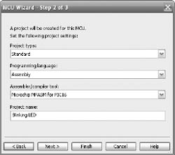
Figure 4.2: MCU Wizard step 2.

Figure 4.3: MCU Wizard step 3.
The suggested values for our first project can be seen in Figures 4.1 to 4.3. This is the complete procedure for configuring a microcontroller using the MCU Wizard.
Now we select the type of project. This is a standard project. The other option allows us to use a pre-compiled hex file that Multisim do not need to recompile again. We do not use this feature here. We select assembly language as our programming language and the compiler automatically shows Microchip MPASM for PIC 16. An appropriate name for the project is Blinking LED.
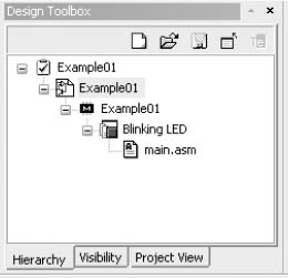
Figure 4.4: Design Toolbox showing the tree view of a MCU project.
In the next window we are asked if we want to create a blank project or add a source code file (Figure 4.3). For our needs, starting with a source code file named main.asm is perfectly acceptable.
Up to this point we can see the tree view for the project in the Design Toolbox window. You can access it via View → Design Toolbox (Figure 4.4). Inside this window we can see the structure of our project and add or delete additional files.
If we double click on each branch of the tree view we can display the content of the file main.asm and start to edit the code. The code is exactly the same as if we were programming a physical microcontroller. In this particular case, a table of commands can be found on the manufacturer’s site:
http://ww1.microchip.com/downloads/en/DeviceDoc/33023A.pdf and in the microcontroller’s datasheet
http://ww1.microchip.com/downloads/en/DeviceDoc/35007b.pdf
We use the following code:
#include ‘‘p16f84.inc’’ ; This includes PIC16F84 definitions for the
; MPASM assembler
;main routine
;enable PORTB as output
CLRF PORTB ; Initialize PORTB by
; clearing output
; data latches
BSF STATUS, RP0 ; Select Bank 1
MOVLW 0x00 ; Value used to
; initialize data
; direction
MOVWF TRISB ; all port pins are outputs
BCF STATUS, RP0 ; Back to Bank 0
main
MOVLW 0x01
MOVWF PORTB
nop
nop
nop
nop
CLRF PORTB
nop
nop
nop
noP
GOTO main
END
Once we have typed or copied the code to the main.asm file we can build it (in the menu → MCU → MCU PIC16F84 U1 → Build. In the spreadsheet window we can see the error log and warnings, if any. In Figure 4.5 we can see the tab for Results.
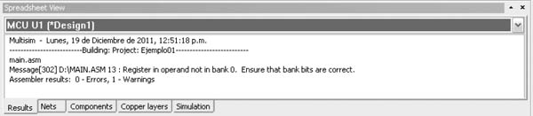
Figure 4.5: Spreadsheet view.
Now that our microcontroller has been programmed we can make the electrical connections. This time we will use a VDD power source and a VSS ground reference. We will also use a digital indicator connected to pin RB0. Note that the Master Clear pin is inverted so it must be tied to VDD for our circuit to operate properly (Figure 4.6). Now we run the circuit by clicking on the run icon (or pressing F5).

Figure 4.6: Electrical connections.

Figure 4.7: Blinking LED.
Notice how the circuit does not have an oscillator connected to its respective pins. The inevitable question is how can we verify/modify the frequency of oscillation for this circuit? The answer can be found right clicking on the microcontroller. In the Value tab we can see that the clock speed is set to 12 MHz. We can make adjustments if necessary but we will leave it as it is for the moment (Figure 4.8).
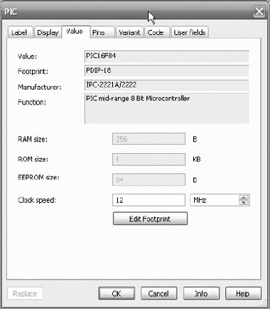
Figure 4.8: Setting the clock speed.
If we have correctly programmed the microcontroller and made the right electrical connections now it is time to run our simulation and see if the LED blinks (Figure 4.7).
As you should have noticed we added an oscilloscope to the circuit. Probably you are seeing the LED flashing very quickly and we would like to measure the flickering frequency. Using cursors on the scope’s window we can see that the signal’s period is 4.32 us thus the frequency is approximately 231 KHz. We can slow it down modifying the code. Try including more nop commands. They are used when you want to waste time. Basically, a nop command tells the microprocessor to execute no operation. The same measurement can be done using the frequency meter from the instruments toolbar.
Example 4.2 Blinking an LED (using C language).
Our first example showed us how to set up a project for assembly language programming. This time we will do the same but with the difference of using C as our programming language. The advantage of using C instead of assembly is that due to it being a higher-level language it’s easier to understand and follow up when reading the code. The disadvantage is that C needs to be translated to assembly by the compiler and this translation sometimes may not be the most efficient way of doing it. In the next section we will see how we can use the debugging tools for optimizing the generated code.

Figure 4.9: Oscilloscope with blinking signal to measure the frequency.
This time we will use the following code:
#include "pic.h"
#define bitset(var,bitno) ((var) |= 1 << (bitno))
#define bitclr(var,bitno) ((var) &= ˜(1 << (bitno))
// a delay function for slowing down the execution
void delay(void)
{
int count = 0;
for (count = 0; count < 250; count++) { }
}
void main()
{
bitclr(STATUS, RP0); // Select Bank 0
bitset(STATUS, RP0); // Select Bank 1
TRISB = 0x00; // Set Port B pins to output mode
while(1)
{
PORTB=0x01; // Turn on RB0
delay(); // Wait
PORTB=0x00; // Turn off RB0
delay(); // Wait again
}
}
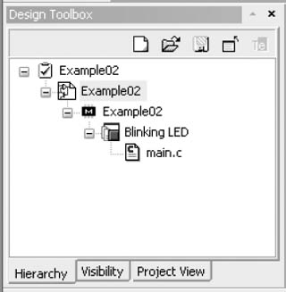
Figure 4.10: Design Toolbox for a C-language project.
We can see that the code is much more compact this time. We now should build the code and run it. Whenever the user wants to run an out-of-date program, Multisim will prompt the user to re-build it. When executed we can see that the LED flashes more slowly this time. In this case, the oscillation frequency can be adjusted by modifying the value of the counter in the delay() function. With different values we can make the LED flash at different speeds. The variable count is an integer and thus it can contain values from -32767 to 32766. If we try to count beyond its limits we will see that it rolls up. This is something that programmers need to be careful.
Going into further details of assembly/C programming is out of the scope of this book. An excellent reference for going deeper into C is found on the book Practical C Programming, by Steve Oualline, O’Reilly 1991 [1].
Multisim has several useful debugging tools when using the MCU module. These tools help the developer to test his/her program and find errors that frequently are hard to detect and fix when the microcontroller is freely running.
In the menu MCU → MCU Windows we can activate the Memory View window. In this window we can see the memory content of the microcontroller. For Example 4.2 it is shown in Figure 4.11. We see the value of each one of its registers and the configuration data. This memory view allows the programmer to inspect the contents of the memory when verifying the behavior of a particular program.
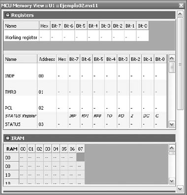
Figure 4.11: Memory contents.
Another frequently used task when debugging programs is stopping it from continuous execution. Being able to stop the program in an arbitrary step of the code allows the programmer to inspect the state of the memory and the related variables. This way a particular condition can be verified and errors can be corrected.
The MCU module has several variants of this function included in the Debug View menu. This function can be activated going to MCU → name of the microcontroller (PIC16F84 U1 in these examples) → Debug View (Figure 4.12).
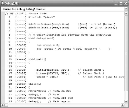
Figure 4.12: – Debug View window showing source file code.
In the Debug View mode we can observe the disassembled code (Figure 4.12). If we are using assembly language for programming this view is very similar, the main difference is that each variable is substituted by its real value. Goto and Jump instructions keep their labels.
When programming using C the disassembled code will show us how the compiler is interpreting the C code and how it is translated to assembly code. This is a great way to learn about going from a higher level language to a low level language like assembly.
In the top part of the Debug View window we can select the option if we want to debug using disassembled code or the source code. The main difference is that the source code contains labels and comments. Sometimes is more useful to work with fully-documented code.
When the debug mode is active we can stop the program when it executes each instruction. This is accomplished using the Step Into function; this function is conveniently mapped to the F11 key. F10 key is mapped to the Step Over function. When we use these two functions we can execute the program one step at a time and use Memory View to observe what is happening with the values of different registers and memory locations.
Similarly, when in debug mode, if we have activated the MCU toolbar (View → Toolbars → MCU, and shown in Figure 4.13) we can select some relevant options that display the code in specific ways. A listing of the tasks that can be done is given in Table 4.1 C code when disassembling so we can verify the correspondence. We can enable/disable the memory addresses. We can see the hexadecimal values for each opcode – opcodes are the numeric equivalent of each one of the commands of the instruction set of the microcontroller. We can show labels and headings as well.
Table 4.1: Buttons in the Debug toolbar. |
|
Button |
Description |
|
Disassembly button. Determines whether we see the listing assembly text or the version from the disassembler. |
|
Show Secondary Language as Comments button. Enables/disables one of two things. If we are looking at the project disassembly view or if we are looking at the listing assembly or disassembly of a file it adds the original source code corresponding to those lines as comments above or beside the assembly. If we are viewing the source code debug listing, this shows the corresponding listing assembly/disassembly as comments below the source code. |
|
Show Line Numbers button. Displays the line numbers in the Debug View. |
|
Show Memory Addresses in Debug View button. Enables/disables the showing of memory addresses for any text that shows source code in any of the debug listing views. |
|
Show Memory Addresses in Assembly Code button. Enables/disables the showing of memory addresses for any text that shows listing assembly or disassembly in any of the debug listing views. |
|
Show Hex Opcodes in Assembly Code button. Enables/disables the showing of the hex values of opcodes for any text that shows listing assembly or disassembly in any of the debug listing views. |
|
Show Jump/Goto Labels button. Enables/disables the showing of the jump/goto labels for any text that shows listing assembly or disassembly in any of the debug listing views. |
|
Show Headings Above Code button. Enables/disables the showing of the heading comments above each block of source or assembly code which labels the different fields being shown in the text. |
4.4 PERIPHERAL DEVICES
Multisim MCU Module offers several peripheral devices for using along with the included microcontroller models. Among them we can find RAM memory, ROM memory, liquid crystal displays, numeric keypads, a virtual serial terminal, a conveyor belt, a holding tank and two different traffic lights (Figure 4.14).
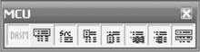
Figure 4.13: MCU toolbar.

Figure 4.14: Example of the included peripherals.
4.5 EXAMPLES
In this section we will show three examples using the elements we have discussed so far. We will be using C for these examples but the reader should feel free to adapt them to use assembly language if desired.
The set of experiments will include this:
• Even/Odd counter
• LCD Display
• Traffic Light
In this example, a microcontroller will receive user input on a pin by the way of an electromechanical switch and the result will affect a count shown on a HEX display.
The circuit is shown on Figure 4.15.
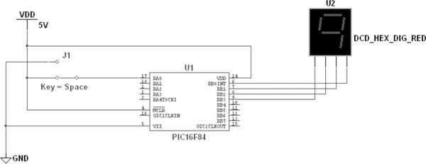
Figure 4.15: Even/Odd counter.
As you can see from the previous figure we have included two elements in this circuit –the switch and the display. The switch can be found in the Basic Components → Switches bin. This switch in particular is a SPDT switch – single pole, double throw. Similarly, the display can be found in the Indicators → Hex Display bin. The type, as is shown on Figure 4.15, is DCD_HEX_DIG_RED.
The switch, as the label shows, is controlled by the space key, this basically means that whenever we press the space key the switch will change from closed to open back and forth. The display receives 4 bits as input and decodes them as a BCD quantity and shows the appropriate symbol.
In order to accomplish this task we need to have a program with the following capabilities:
• Read from the input pin RA0 and write a count to Port B. This configuration is made by setting the right bits to the TRISA and TRISB registers.
• Count from 0 to 15
• Modify the count to show only even numbers or odd numbers depending on the switch’s position
The proposed solution is a program that addresses directly these requirements. First we will configure the microcontroller for input on Port A and output on Port B. Then we will use a For loop for counting from 0 to 15 (that is, from 0x0 to 0xF in HEX notation) and we will write data to the output port using the input on Port A pin 0 (RA0) as a modifier so it can show even numbers or odd numbers. There is also an ancillary function called delay so the count does not flash too quickly on the display.
The proposed solution is shown next:
#include "pic.h"
#define bitset(var,bitno) ((var) |= 1 << (bitno))
#define bitclr(var,bitno) ((var) &= ˜(1 << (bitno))
int i;
// delay function to slow things down
void delay(void)
{
int count = 0;
for (count = 0; count < 250; count++) { }
}
void main()
{
bitclr(STATUS, RP0); // Select Bank 0
PORTB = 0x00; // Clear Port B
bitset(STATUS, RP0); // Select Bank 1
TRISB = 0x00; // Set Port B pins to output mode
TRISA = 0xFF; // Set Port A as inputs
while(1)
{
for(i=0;i<16;i+=2)
{
PORTB=i-RA0; // We subtract the value of RA0 so we can
delay(); // make an even or odd count
}
}
}
When this program is built (compiled and linked) we can start the simulation and see how the display counts odd numbers when the switch is connected to 5V and when it is tied to ground it will count even numbers. The book’s website shows an animation of this circuit.
Example 4.4 Writing data on an LCD display.
The following example will make use of the liquid crystal display (LCD) included on the Advanced Peripherals library. This kind of displays is based on a very common controller –the Hitachi 44780. Manufacturers still use most of the original specifications so they are interoperable and backwards compatibility is not an issue.
Figure 4.16: LCD terminals.
As we can see in Figure 4.16 there are several connection pins on this module. We have the usual supply pins (VCC and GND), a control voltage (CV) used for adjusting the contrast, 3 control pins (E, RS and RW) and 8 data pins (D0 . . . D7). We will connect them as follows:
• VCC at 5VDC
• CV, GND and RW at 0VDC
• E and RS at RA0 and RA1, respectively,
• D0 to D7 directly connected to Port B
In order to display characters on an LCD we must first initialize it. Our program will execute the initialization routine upon start. Then we will define an ASCII string that will be sent and displayed.
The complete circuit is shown on Figure 4.17. As you can see we have used LED indicators as a way to visually inspect that the digital signals are being sent as expected. Also now we are using a more common display type, a 16x2 characters display. That means it has two rows, with 16 characters each one.
The program for the PIC is:
#include "pic.h"
#define bitset(var,bitno) ((var) |= 1 << (bitno))
#define bitclr(var,bitno) ((var) &= ˜(1 << (bitno))
void delay(void)
{
int count = 0;
for (count = 0; count < 250; count++){ }
}
// toggle function toggles the value at RA0
void toggle(void)
{
RA0=0;
RA0=1;
}
// lcdInit function is the initialization procedure for a 16x2 display
void lcdInit(void)
{
RA1=0;
delay();
PORTB=0x38; // configures the display as 16x2, 5x7 font and 8 bit bus
toggle();
PORTB=0x06; // moves cursor to the right
toggle();
PORTB=0x0F; // turns on the display
toggle();
PORTB=0x01; // clears and sets the cursor at the home position
toggle();
delay();
RA1=1;
}
void main()
{
bitclr(STATUS, RP0); // Select Bank 0
bitset(STATUS, RP0); // Select Bank 1
TRISA = 0x00; // Set Port A pins to output mode
TRISB = 0x00; // Set Port B pins to output mode
lcdInit();
delay();
PORTB = 0x45; // writes letter E
toggle();
PORTB = 0x41; // writes letter A
toggle();
PORTB = 0x53; // writes letter S
toggle();
PORTB = 0x59; // writes letter Y
toggle();
PORTB = 0x20; // writes a space
toggle();
PORTB = 0x41; // writes a letter A
toggle();
PORTB = 0x53; // writes a letter S
toggle();
PORTB = 0x20; // writes a space
toggle();
PORTB = 0x41; // writes a letter A
toggle();
PORTB = 0x42; // writes a letter B
toggle();
PORTB = 0x43; // writes a letter C
toggle();
PORTB = 0x20; // writes a space
toggle();
}
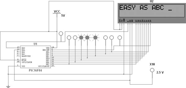
Figure 4.17: Circuit for testing an LCD.
We can see a pair of functions at the top of the program: toggle() and lcdInit(). The toggle function just sends a pulse going from low to high whenever we want a new data to be fed into the display. The delay function is the same we have used in the previous Examples 4.2 and 4.3.
When the program is compiled and the simulation starts we can see a quick flash of the LEDs and after a while we can see that letters start to appear on the display. Since this is a small message we are storing it right in the microcontroller’s memory. In a real world situation messages are usually longer and need to be stored in an external memory and read as needed.
The data in the main section of the program is the message we want to display. In this case, the message reads EASY AS ABC. Each character is coded into its ASCII representation in hexadecimal notation. The used sequence (in hexadecimal) is:
45-41-53-59-20-41-53-20-41-42-43
As a practical exercise try to find out the code for the space, for the letter A and, using an ASCII chart, try to see how to convert this string to all lowercase characters (Hint: they are separated a fixed distance).
Now we will focus our attention on the lcdInit() routine. The purpose of this function is to prepare the LCD for the right number of rows and characters, clear the screen and position the cursor where we want. In Multisim we can get along without initializing the display just fine, but anyway it is a good practice –and certainly a requirement most of the time –to always initialize a display before using it.
If we look carefully at the connections in Figure 4.17 we see that there is a control pin labeled RW. This signal is always tied to ground because we will be writing to the display. The reason for it to be there is that a read/write procedure is used when the user wants to define custom characters or reading the status of the several function of the display during execution.
Example 4.5 Controlling a traffic light.
The next example will make use of the included traffic light from the Advanced Peripherals/Misc Peripherals menu. This device along with the conveyor belt and the holding tank are part of the educational edition of Multisim and are mostly used when teaching and learning about ladder logic. As a matter of fact, microcontrollers and PLCs (programmable logic controllers) are commonly used when working in similar situations in the real world so what you learn in this chapter can also be applied to a broad range of topics.
A microcontroller can only output very small currents. It is common to see maximum ratings in the order of 40 mA on each pin. This current is not enough for powering a lot of common devices, like the lights on a traffic light. We must find another way of controlling a large current with a small control signal. In this specific case we are going to use a component called voltage controlled switch. This component can be found under the Components → Basic → Switch menu as we see on Figure 4.18.
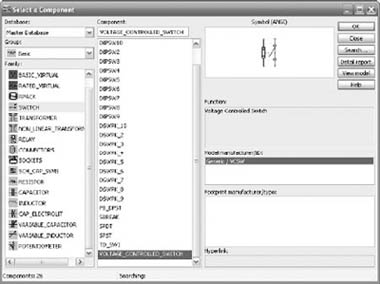
Figure 4.18: Voltage controlled Switch.
This switch is special because it gives us the power to control devices that need a current larger than a few miliamperes. Most of the time these switches are made of transistors or electromechanical relays. We will use it as the switching element for controlling the inputs of the Traffic Light that can be found on the Advanced Peripherals menu. This traffic light turns on each one of its lights whenever a voltage is present at the input. If we would have chosen the microcontroller pins as the control signals we would have seen that the lights never turn on, or perhaps they flash very quickly. A real microcontroller would not withstand such operation and a resulting damaged pin would be the consequence of this operation.
The connections are shown on Figure 4.19. The control signals come from the microcontroller and they are used as inputs on the voltage controlled switches. These switches have their threshold voltage modified to turn on and off at 2.5 volts.
We can also see that the other side of the switch has one connection going into the traffic light and the other side is left open.
The microcontroller is programmed with a very basic main function. This does not mean it is a simple function. Here you can see it:
void main()
{
bitclr(STATUS, RP0); // Select Bank 0
bitset(STATUS, RP0); // Select Bank 1
TRISB = 0x00; // Set Port B pins to output mode
state01(); // red on one side and green on the other
blinkGreen01(); // green light 01 blinks
amber01(); // still red on one side and amber on the other
state02(); // this state is like state 01 but inverted
blinkGreen02(); // green light 02 blinks
amber02(); // amber light on one side and red on the other
}

Figure 4.19: Circuit for a traffic light controller.
The first part is just the setup of the PORTB. Then we see a sequence of functions state01, blinkGreen01, amber01, state02, blinkGreen02, and amber02. These functions are defined in the previous part of the program and it is there where the action happens. The main function was intentionally left as just a way of calling the functions just to explain more clearly the sequenced nature of this problem. We could have written every step as part of the main function and the program would have run exactly the same.
The operation of the traffic light is defined as follows:
1. A green light on one side is accompanied by a red light on the other side.
2. After some seconds, the green light starts to blink briefly before going into amber.
3. When the amber light turns off, the red light and the green light are reversed with respect to the initial state.
4. The blinking and amber lights happen on one side as the other holds the red light on.
5. Everything repeats again.
The complete program is shown next. There are three different delay functions. These may need tuning when simulating this example on different computers since their timing depends on the processor’s speed.
#include "pic.h"
#define bitset(var,bitno) ((var) |= 1 << (bitno))
#define bitclr(var,bitno) ((var) &= ˜(1 << (bitno))
// this is a standard delay function
void delay(void)
{
int count;
for (count=0;count < 255;count++) { }
}
// this delay is a little bit longer than the previous one
void delayMedium(void)
{
int count;
int count2;
for (count=0;count < 255;count++) {
for (count2=0;count2 < 3;count2++) { }
}
}
// this is the longest delay
void delayLong(void)
{
int count;
int count2;
for (count=0;count < 255;count++)
{
for (count2=0;count2 < 10;count2++) { }
}
}
void state01(void)
{
PORTB=33; // red on one side and green on the other
delayLong(); // long delay time on this state
}
// Green light 01 blinks four times
void blinkGreen01(void)
{
PORTB-=1;
delay();
PORTB+=1;
delay();
PORTB-=1;
delay();
PORTB+=1;
delay();
PORTB-=1;
delay();
PORTB+=1;
delay();
}
// amber light on and red on
void amber01(void)
{
PORTB=34;
delayMedium();
}
// like state01 but inverted
void state02(void)
{
PORTB=12;
delayLong();
}
// green light 02 blinks four times
void blinkGreen02(void)
{
PORTB-=8;
delay();
PORTB+=8;
delay();
PORTB-=8;
delay();
PORTB+=8;
delay();
PORTB-=8;
delay();
PORTB+=8;
delay();
}
// amber and red on
void amber02(void)
{
PORTB=20;
delayMedium();
}
void main()
{
bitclr(STATUS, RP0); // Select Bank 0
bitset(STATUS, RP0); // Select Bank 1
TRISB = 0x00; // Set Port B pins to output mode
state01(); // red on one side and green on the other
blinkGreen01(); // green light 01 blinks
amber01(); // still red on one side and amber on the other
state02(); // this state is like state 01 but inverted
blinkGreen02(); // green light 02 blinks
amber02(); // amber light on one side and red on the other
}
When the simulation is running we can see the complete sequence as a representation of a working traffic light. First the cars in one street have the red light on while the cars on the other street can cross safely. After a given time (defined in the delayLong() function) the green light starts to blink before going into amber and finally to red. At this time the traffic light allows traffic on the other street while stopping the cars on the other street.
This example concludes the chapter on Multisim capabilities for simulating microcontrollers. We went through the steps on getting an appropriate environment for writing and compiling programs, both in assembly language and in C. Then we showed a set of applications that involved a program being compiled and transferred to the microcontroller and external peripherals being connected to it.
4.6 CONCLUSIONS
A simulator that handles a mixture of digital and electric circuits is a very powerful tool. A designer can benefit from such software the moment he is free to explore new variations on the design without the worries of time-consuming recalculations.
This chapter joins the analog/digital world with the world of microprocessors, the hearts of today’s devices, gadgets and appliances. As we have shown, the inclusion of microcontrollers in other types of circuits is a seamless job in Multisim.
Through examples we have show the reader some of the possibilities that Multisim opens. The reader should feel free to try more complex programs and connections to more peripherals or external circuits if so he/she desires.
REFERENCES
[1] S. Oualline, Practical C Programming, O’Reilly, Sebastopol, CA, 1991. Cited on page(s) 98