9
IoT-Based Health Monitoring and Tracking System for Soldiers
Kavitha N.* and Madhumathy P.
Department of ECE, RV Institute of Technology and Management, Bangalore, India
Abstract
In the present era, securing our nation soldiers’ health is one of the primary duties of an army for securing our nation from enemy warfare. The nationwide protection is primarily dependent on the ground army, air-force, and navy. The soldiers play a significant role in securing our nation. Our country’s defense department must be equipped with the requirement to secure our soldier’s health. Hence, we propose an IoT-based system to monitor and track the soldier’s health; mainly, it is required for army persons who take part in unusual mission activity. The soldier’s health has been monitored by IoT-based system and located through GPS (Global Positioning Systems). This is feasible by using the temperature sensor, heartbeat sensor, and technologies involved in communication required for health related issues. Here, initially, soldier’s body temperature is measured using LM35, and pulse rate using a heartbeat sensor and the values obtained are being compared with the threshold value kept on the basis of standard human body value; once the monitored value of the soldier exceeds that threshold value, automatically, control room will receive the information by specifying value obtained on the sensor.
Depending on that value, the doctors being present in the control room will take immediate action based on the severity of the patient. The immediate medication will be started by tracking the soldier’s location in the war field by attaching the smart sensors to the soldier’s body. For complete mobility with a personal server, it has been implemented. It would, in turn, through wireless mode give a message to the server base station. Depending on unique IP address, soldiers have been identified at the earliest.
Keywords: Health monitoring system, IoT, wireless health sensors, embedded processor, GPS, temperature sensor, cloud computing
9.1 Introduction
Indian army is one of the largest standing armed forces in the world with 255 active troops counting 1,200,255 and reserve troop counting nearly 990,960 [2]. The unavailability of information about the injuries of army people would lead to permanent disability/death, and majorly causalities are not due to direct assaults in the battle field but due to injuries.
The control room will be having real-time information which includes exact location of the soldier and health is made immediately available then immediate medication can be provided and soldier’s safety issues can be taken care. The main cause for army suffering is due to unavailability of information regarding health and unable to track the position of soldiers. The soldier’s safety has many drawbacks such as failure in providing continuous communication about current location of soldiers in-par with the control room, requires instant medical interest, and operations underneath various geographical conditions, which are the some important safety issues.
Improving country’s security, several relief funds are released for disasters caused due to natural or man-made; Armed Forces have been strengthened by providing financial support to the defense equipment by taking the initiative of Make-in-India. In latest IT scenarios, cloud computing is becoming an imagined paradigm shift. Cloud computing provides a centralized virtual environment for users without any active physical infrastructure investment. Clients can store cloud data and run internet applications. Computing is a massive pool of services that can provide customers with a system and a small-to-large hardware platform. The server that stores data from a specific user is leased/rented to the user on a monthly basis. This use can be increased or reduced and the customer will only be charged according to the use [7].
The conventional techniques for monitoring soldiers’ health in battle field were tracking systems based on GSM and ZigBee, walkie-talkie. These methodologies had few drawbacks such as signal loss, noisy signals, and bulky in nature with higher installation cost. Hence, we need a system to overcome these drawbacks, wherein we aim at a system which is at lower cost, wireless system, portable, and highly reliable in tracking the soldier’s life on the battlefield. In addition to that, the system should be in such a way that it can be used in real-time scenarios for providing immediate medication for the needy soldiers. There is no single mechanism to provide all of the specified services. However, we can identify a very important mechanism that is cryptographic technique that supports all forms of information integrity. Information encryption is the most common way of providing security. The anticipated is an IoT system which would continuously communicate about the soldiers’ health condition and also the location.
Here, GPS can be used with proposed system for monitoring temperature of body and pulse rate of each and every individual. The monitored health parameters have been conveyed through IoT-based system to control room for further actions, wherein as soon as the location and position of the soldiers have been tracked, they have been guided to medication centers for further actions.
9.2 Literature Survey
Literature survey is the reference of some of the approaches already used. So, any new approach should be developed by the reference of some of the old and existing approaches.
GPS-based system for tracking and monitoring solders health [1]: The primary challenges that exist in military operations are to provide continuous communication with base (control room). It requires vigilant preparation and synchronization for appropriate routing among soldier’s organizations. Hence, GPS is used to track the soldier location which has been communicated to control room station for further action, wherein communicating the relay information within shortrange at high speed using bio-medical sensor, mainly by implementing M-Health system. Such implementation secures soldiers’ health and, in turn, country will be secured. In addition to that, real-time video is also provided. These real-time information helps in reducing the casualties caused due to war, and also warnings are given to soldiers by providing critical information.
A real-time autonomous soldier health monitoring [2]: The main motivation for this is Indo-Pak War that took place on 1971, in that 54 soldiers families were declared missing. Over 160 million people died in wars. This is mainly due to the fact of incessant warfare which took place in modern times. Hence, a wireless sensor network has been used wherein multifunctional sensor nodes have been used which consumes less power, cheap, and multifunctional with miniaturization to communicate for short distances, which are integral part of military C4ISRT system. It would ensure safety of every soldier in the armed forces by making them to wear a device which would periodically update pulse rate value of the of the wearer, which has transmitter at source in GPS module which would track the location of the wearer during difficult situations, such as intimating immediately when pulse rate falls below the threshold.
An IoT-based patient monitoring system using Raspberry Pi [3]: The Raspberry Pi is one of the major platforms to learn IoT, since it provides low cost and tiny platform with Linux server. On Raspberry Pi, general purpose I/O pins and actuators have been interfaced. Here, patient’s body temperature and heart rate are monitored using specialized sensor. Few sensors such as temperature, respiration, accelerometer, and heartbeat have been connected to Raspberry Pi which acts as small clinic. The data collected through Raspberry Pi has been transferred through wireless mode to IoT website through internet, since MAC address has been already registered to the internet and also been added to the board. After connecting Raspberry Pi and sensors, on the monitor screen, output is obtained when we connect all system terminals to Raspberry Pi board.
Cloud computing–based smart system to connect e-health sensors [4]: Cloud computing is one of the technological services providing various computing resources which are compatible, namely, services and application. Since cloud computing is flexible and modern technique to manage with less effort, automated techniques with high storage capacity and low cost. Raspberry Pi and wireless health sensors are connected to accumulate the data being sent from sensors, further the accumulated data has been transmitted through wireless mode to the cloud through platform services. This combination of Raspberry Pi with cloud computing and wireless sensor networks would result in novel generation of technology in terms of monitoring the patient, and efficiency of medical staff performance has been improved and also a range of data mining method are applied to take out and analyze patients data in minimal cost.
Hence, a system is designed to accurately monitor soldiers’ health accurately with system architecture.
9.3 System Requirements
The process of dividing a multipart topic into minor blocks for enhanced understanding is called analysis. In engineering field, the parameters that we consider are dimensions of the system, involved mechanism, and also structures for investigating the activity called analysis. The life cycle of the task starts at this analysis phase. In this phase, only a multipart task has been divided into exhaustive requirements of business. It also guides us in collecting the required entities on the basis of application complexity and also the path to be followed when task documents have been created. The entire procedure has a repetitive involving a method to gather the required documents, and effective communication and requirements are being managed.
9.3.1 Software Requirement Specification
A prerequisite requirement of system software to be developed is called software requirements. Software Requirement Specification (SRS) consists of non-functional requirements and also software functions. Software engineering is composed of specification, elicitation, validation, and analysis of software requirements.
9.3.2 Functional Requirements
- • The system must send a message to the owner whenever a soldier is in danger.
- • Each sensor senses respective input, processes, and gives desired output.
- • Basically, to track any soldier, we need latitude and longitude which will be obtained from GPS and in microcontroller memory it is being stored.
- • The tracked coordinates of soldier’s position have been displayed on LCD screen along with status of their health is also been displayed.
9.4 System Design
Designing of a system is a process of defining system architecture which has a modules defined for a system requirements being specified as shown in Figure 9.1. It is a technique to develop application oriented product “blends the perspective of marketing, design, and manufacturing into a single approach to product development”; further, product which is to be manufactured has been designed by considering the information about marketing.
System Architecture
The ARM7 TDMI core is 32-bit RISC embedded processor which yields in preeminent arrangement and also the characteristics of area and power. The processor is of smaller size, consumes less power, and yields good results.
- • The 32-bit ARM processor operates with higher flexibility and maximum performance.
- • Both instructions and data are of 32-bit.
- • It supports pipelining in three-stages.
- • The operation is fully static.
- • It has a coprocessor-type interface.
- • It has an embedded ICE debug facilities.
- • Specific process technologies have been ported to generic layout.
- • SoC integration process has been simplified by unified memory bus.
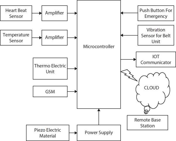
Figure 9.1 Functional block diagram.
- • ARM7TDMI-S is binary-compatible family such as ARM9, ARM9E, and ARM10 where higher level microcontroller or microprocessor is used to port design.
- • The devices which are battery-powered should consume less power and design is static.
- • Coprocessors are used for extending the instruction set with specific requirements.
- • Debug facilities in real-time is carried out by embedded ICE-RT and optional ETM units.
The performance of ARM’s processor is advantageous compared to conventional 16-bit processor because density standard ARM code is twice. This is probable only when Thumb code act as ARM code on 32-bit register. Since Thumb code is equivalent to 65% code size of ARM due to which the performance is equivalent to 160 % of ARM processor. This yields in full speed execution of flash implementation in ARM mode.
9.4.1 Features
- • ARM7TDMI-S is 16-bit/32-bit microcontroller comprising in-built flash memory of 32 to 512 KB, static RAM of 8 to 40 KB with LQFP64 package. It operates at 60 MHz having interface/accelerator of 128-bit wide.
- • It has boot loader software which is in-built with In-System Programming/In-Application Programming (ISP/IAP), and it also includes 400-ms single flash sector and 256 bytes programming in 1 ms.
- • It has a capability of tracing instruction execution at a higher speed rate and also offers on-chip Real Monitor software by embedded ICE RT.
- • It has endpoint RAM which is 2-KB device controller with full-speed compliant.
- • LPC2146/48 uses DMA in-built RAM of 8 KB to USB.
- • LPC2142/44/46/48 provides variable analog output by DAC of single 10-bit.
- • It has PWM unit, watchdog having two timers/external events counters of 32 bit.
- • It has a clock input of 32 kHz Real-Time Clock (RTC) consumes less power.
- • It has SSP with variable data length and buffering capabilities, 16C550, two UARTs, 400 kbit/s, two I2C-bus, and SPI.
- • Vectored Interrupt Controller (VIC) is used to configure the priorities and has vector addresses.
- • Tiny LQFP64package has 5 V tolerant I/O pins out of 45.
- • On the whole 21 external interrupt pins exist.
- • It has in-built 60-MHz CPU clock with operating range from 1 to 25 MHz.
- • It has power-down and idle as the power saving modes.
- • The power optimization is carried out by either enabling or disabling the peripheral functions and clock scaling.
- • Through external interrupt, processor can be switched from power-down mode to power-on mode.
- • CPU operates at a voltage 3 to 3.6 V using POR and BOD circuits on a single power supply chip.
9.4.1.1 On-Chip Flash Memory
There are different types of flash memory system, namely, LPC2141/42/44/46/48 include a 32, 64, 128, 256, and 512 KB, respectively. To store data as well as code and flash memory is used. There are several ways to program flash memory such as through serial port programming system. When application is running, flash may be erased by application program, which is flexible for storing data, upgrading field firmware, etc. Here, 100,000 erase/write minimum cycles have been provided for a data-retention of 20 years.
9.4.1.2 On-Chip Static RAM
In-built static RAM is used to store code and data. It uses 8-, 16-, and 32-bit SRAM in LPC2141, LPC2142/44, and LPC2146/48, respectively. Suppose LPC2146/48 is used as 8-KB SRAM, then it is used for storing code, execution, and data, and USB is mainly used for the block intended to.
9.4.2 Pin Control Block
Most of the microcontroller pins are multifunctional. The on-chip peripherals and pin connection is controlled through multiplexers by configuration registers. To specific pin, peripherals are connected and activated by enabling interrupts. In a hardware environment, few pin peripheral functions are not assigned; those pins are considered as undefined. The microcontroller functionality is to have a pin select registers in a Pin Control Module. Ports 0 and 1 are constituted as input when we reset all pins with few exceptions: JTAG is assumed to be functional by JTAG pin when we enable debug pin; Trace is assumed to be functional by Trace pin when we enable trace. The open drain interface pins are I2C0 and I2C1.
9.4.3 UARTs
There exist two UARTs in LPC2141/42/44/46/48. Handshake interface with full modem control is provided along with standard transmit and receive data lines compared to other microcontrollers such as LPC2000. For both UARTs, i.e., PC2141/42/44/46/48 fractional baud rate has been generated to enable the microcontroller with standard rates such of 115,200 for more than 2-MHz crystal frequency. Hardware has been fully implemented with flow-control functions using auto-CTS/RTS.
9.4.3.1 Features
- • Based on FIFO, 16-byte data has been received and transmitted.
- • FIFO receiver triggering points are at 1, 4, 8, and 14 bytes.
- • Without external crystal frequency baud rate has been generated by built-in fractional baud rate generator.
- • Transmission flow control is implemented on FIFO basis using XON/XOFF software on both UARTs
- • Interface signals in standard modem are equipped in LPC2144/46/48 UART1 module providing hardware flow control using auto-CTS/RTS.
9.4.4 System Control
A control loop is being used for regulating other devices behavior, directs, and manages the control system.
9.4.4.1 Crystal Oscillator
External crystal frequency ranges from 1 to 25 MHz is used as oscillator. Here, fosc is referred as oscillator output frequency and CCLK is referred as ARM processor clock frequency. Until and unless PLL is running and connected, both clock frequencies have same value.
9.4.4.2 Phase-Locked Loop
The clock frequency is given as an input to phase-locked loop (PLL) which ranges from 10 to 25 MHz. The Current Controlled Oscillator (CCO) is multiplied with input frequency which ranges from 10 to 60 MHz, which ranges from 1 to 32 but the microcontroller family which we have considered here to which integer value cannot exceed 6 because of the CPU’s upper frequency limit. Since desired output frequency is provided by PLL due to the CCO frequency ranges from 156 MHz to 320 MHz, hence no additional divider is required in the loop. The PLL chip which is reset can be enabled by software. The PLL is activated and configured by programming; PLL is connected to a clock source after it has been locked then 100 μs is given as settling time.
9.4.4.3 Reset and Wake-Up Timer
Watchdog reset and RESET pin are two sources on the LPC2141/42/44/46/48. The glitch filter is present along with Schmitt trigger input in RESET pin. Wake-up timer has been reset using chip reset assertion which would be present until it de-assert external reset, and initialization of on-chip flash controller will be completed, passing of specific number of clocks and working of the oscillator.
The processor will start executing at address 0 when we remove internal reset which is nothing but reset vector. Predetermined values are used for initialization of all peripheral registers.
It verifies whether chip operation and oscillator are functional before instructions are executed. It mainly plays a major role; when we turn off aforementioned functions due to some reasons, wake-up timer is used for processor wake-up from power-down mode caused due to turning off oscillator and other functions.
Before executing any code, wake-up timer will monitor crystal oscillator. The oscillator yields a significant amplitude signal for driving the clock signal if there is a power-down mode. There are many factors that are dependent on amount of time taken such as value of VDD ramp during power on mode and also crystal type such as quartz crystal behavior during the present ambient conditions and also there signal depending on external circuitry.
9.4.4.4 Brown Out Detector
There exist two levels of voltage monitoring on VDD pins such as LPC 2141/42/44/46/48. The BOD interrupt signal is asserted to the VIC, if the voltage is less than 2.9 V, where VIC is connected to BOD interrupt signal. Using interrupt signal, it can be enabled otherwise software is used to read the signal being monitored and will be stored in the specific register. In next stage, detecting low voltage is carried out if voltage on VDD pin is less than 2.6 V which would, in turn, deactivate LPC 2141/42/44/46/48. This low voltage would make the chip unreliable and also avoid changes in the flash memory. The reset down voltage less than 1 V is maintained by BOD circuit simultaneously overall reset is maintained by POR circuitry. Hysteresis is maintained for threshold voltages of 2.9 and 2.6 V. During the typical process, 2.9-V detection is allowed by hysteresis which will be reliable interrupt or it can be an event loop for sense the condition which has been regularly executed.
9.4.4.5 Code Security
The applications can be controlled or debugged from LPC2141/42/44/46/48 feature. When valid checksum is detected after on-chip boot loader is reset from flash, it has been read from address 0x1FC as 0x8765 4321 in flash, and the flash code has been protected when debugging has been disabled. We can enable the disabled debugging by using the ISP for full chip erase.
9.4.4.6 External Interrupt Inputs
There are few selectable pin functions which are level sensitive external interrupt inputs in LPC 2141/42/44/46/48. We can have four interrupt signals which are independent with respect to external events when we combine the pins. From power-down mode, we can make the processor to power-up mode by using inputs of external interrupt. For external interrupts, few capture input pins are used.
9.4.4.7 Memory Mapping Control
The interrupt vectors mapping will be changed by Memory Mapping Control from address 0x00000000. To flash memory or to static RAM interrupt, vectors have been mapped which helps in controlling the interrupts for uninterrupted code execution at different memory spaces.
9.4.4.8 Power Control
The idle and power-down modes are two reduced power modes in LPC2141/42/44/46/48. Until and unless either reset or interrupt occurs, instruction execution will be suspended. In idle mode, processor resumes execution based on interrupt generation and peripheral function operation will be continued. Usage of power by the processor will be eliminated during idle mode. Chip does not receive any internal clocks since oscillator is shut down during power-down mode. During power-down mode, the values of peripheral registers, SRAM, and processor state registers have been conserved and chip output pins logic levels remain static. Using either specific interrupts or reset, normal operation can be restarted from the power-down mode which can function without the intervention of clocks. RTC can be kept active during power-down mode by selecting clock source of 32-kHz external clock as an alternative to PCLK to ensure that RTC is active even in the power-down mode by enabling microcontroller. Keeping RTC active, we can increase power-down current. It will be lesser than idle mode.
In certain application, several individual peripherals need to be in off state if it is not used; it has been controlled by peripherals power control which would save the power both in active and idle mode.
9.4.5 Real Monitor
Real-time debugging is carried out by Real Monitor manufactured by ARM Inc., which is one of the configurable software modules. It is one of the backgrounds running in lightweight debug monitor where user will be debugging their foreground application. In presence of embedded ICE logic, DCC is used to communicate with the host. Here, Real Monitor software with specific configuration is programmed into on-chip flash memory. In the on-chip flash memory, Real Monitor software has been programmed containing specific configuration in LPC2141/42/44/46/48.
9.4.5.1 GPS Module
In most of the electronic gadgets and automobiles, GPS module has been used for tracking the commerce all over the globe. This module would give specific position and time of the device instantaneously. To get the tracking details, mainly, we require a GPS receiver which is cheaper and tiny.
It took decades of research to create GPS module to get exact location from any point to anywhere. Since 1970 till date, several GPS satellites are launched for tracking the device. Through dedicated radio frequencies (RFs), satellites will be continuously transmitting the data down to earth. In turn, tiny GPS receivers will have antennas and tiny processors for receiving the data through the antenna directly from GPS satellites which help in estimating the position and time. Ground stations and constellation of satellites are used by the GPS receivers to estimate location and time from any point on earth. All the time, there will be a minimum of 24 active satellites orbiting above earth over12,000 miles. The satellites positions are built in such a way that there will be at least 12 satellites above your location.
The RF which ranges from 1.1 to 1.5 GHz is used for transmitting the information to the earth through visible satellites. GPS module is used for estimating time and position by performing mathematical calculation on data transmission and reception.
GPS receivers were able to accurately estimate time and position based on information being forwarded to earth through satellite. Due to the presence of accurate atomic clock, GPS satellite was able to estimate the time accurately. Mainly, time has been estimated accurately by the combination of arrival times of various points on the sky and atomic clock timing at which it has been moved to earth. That is from the visible satellites, time stamp and data will be received by the GPS module, and this would give the each satellite distance to GPS receiver.
Through serial interface in various formats, GPS data has been exhibited. There are two types of message formats such as standard and nonstandard. NMEA data is given as output from all GPS receivers. The lines of data formatted in NMEA standard are called sentences. The various data bits in each sentence are organized in such a way that data has been separated by commas.
9.4.6 Temperature Sensor
- • The temperature measured by estimating the ratio between electrical output to temperature by LM35 which has temperature sensor
- • It accurately measures the temperature than thermistor.
- • The sensor circuitry is not subjected to oxidation it is sealed.
- • LM35 is more efficient than thermocouples in generating higher output voltage and output voltage need not be amplified.
9.4.7 Power Supply
The power supply of electronic circuits and other devices are designed for converting AC mains with high voltage to appropriate less supply voltage. Each block executes a specific function. Regulated DC power supply is one which preserves constant output voltage irrespective of load variations or AC mains fluctuations. Power supply block diagram is shown in Figure 9.2.
9.4.8 Regulator
Fixed voltage such as 5V, 12V and 15V and also output voltages which are a variable are also present in voltage regulator ICs. It has been rated based on the upper limit current is passed. Most regulators has overload protection and thermal protection. Unlike power transistors fixed voltage regulator also has 3 leads such as 7805 +5V 1A regulator. For regulating the power supply positive lead needs to be connected to your unregulated DC power supply.
9.4.9 LCD
In today’s market, 1 Line, 2 Line, or 4 Line LCDs are most commonly available, it holds up to 80 characters with a single controller, whereas 2 HD44780 controllers is used if we want to hold up more than 80 characters. This would help in creating animated text scripts and so on other than displaying simple static characters. Usually, the LCD switch 1 controller has 14 Pins and 16 Pins, i.e., additional pins are connections with backlight LED.

Figure 9.2 Functional block diagram of power supply.

Figure 9.3 Heartbeat sensor.
9.4.10 Heart Rate Sensor
The heartbeat is measured through sensor by placing finger on it. To determine heartbeat, the microprocessor is interfaced to sensor showing digital output as shown in Figure 9.3. Depending on each pulse in the finger blood flow, it has been measured on light modulation principle. Usual quiescent heart rate for adults ranges between 60 and 100 beats per minute (bpm). Therefore, 60 to 100 bpm is the threshold kept for measurement. Hence, if the soldier heartbeat exceeds, the threshold value automatically information will broadcast to control room.
9.5 Implementation
A specific algorithm is implemented through computer programming and deployment of computer system. World Wide Web Consortium is implemented through web browsers and programming languages are implemented through software development tools.
When an interface is implemented through concrete class object-oriented programming occurs as special case, the interface has concrete class implementation and it includes implementations methods precise by the interface.
In many industries, clients have been guided regarding the purchase of hardware or software which is referred as the implementation of post-sales process. It mainly requires systems integrations, analysis of scope, cus-tomizations and policies of user, and training and delivery of users. Task management methodologies are used by task manager for overseeing the steps. Several professionals are unaware of business and technical analysts and so on in the knowledge-based economy for implementations of software.
For successful implementation of a system in a systematic way, a huge number of tasks are required to be carried out which are inter-related. Making use of methodology which is well-proven for implementation and combining the professional recommendation will aid but often it leads to deprived planning and insufficient resourcing would mainly leads to many problems during task implementation which would hinder in achieving the desired results.
9.5.1 Algorithm
- 1. Pulse rate sensor is used for computing the soldier pulse rate. The pulse rate will be tracked once it traverses threshold level then automatically sends attentive message to control room and also the pulse rate being displayed on LCD.
- 2. LM35 temperature sensor used for measuring soldier body temperature, and if it exceeds entry level, then automatically attentive note is being forwarded to control room.
- 3. Further using GPS receiver, exact location of soldier has been tracked and information is passed to control room.
- 4. In case of emergency situation, panic button will be pressed by the soldiers to intimate the control room.
9.5.2 Hardware Implementation
ARM Microcontroller: It is one of the Acorn RISC Machine, and it has a fewer instruction set for computation in a various environments of a computer processors. It has been developed by ARM Holdings, and to other companies, licenses are provided. The products are designed by their own which as either systems-on-chips (SoC) or systems-on-modules (SoM) architectures which integrates interfaces, memory, radios, etc. Keeping this instruction set, core has been designed and licenses are provided to other companies to implement in their own products.
Universal Asynchronous Receiver-Transmitter (UART): It is a device which provides asynchronous serial communication where transmission speeds and data format are configurable. Outside the UART, driver circuit being present manages the electrical signals. For serial communications, UART is used as IC in serial port to connect computer or peripheral device. Similarly synchronous operation is also supported by Universal Synchronous and Asynchronous Receiver-Transmitter (USART).
Controller: The controller controls the working and mechanisms of heartbeat sensor, vibration sensor, and GPS.
Heartbeat Sensor: It measures the soldier heart rate per minute and soldiers’ health conditions have been monitored by keeping threshold value as the reference. If it exceeds or decreases the set threshold value, then it is considered that soldier is in critical condition.
Temperature Sensor: Body temperature is measured by this sensor. The temperature range at which it is operated ranges from –55°C to 150°C. The standard human temperature is around 370°C [6]. Hence, 300°C to 400°C is considered as threshold value.
GPS: This tracks soldier movements in the battlefield. This module uses a geostationary satellite where it is possible to know the location of the soldier.
Wi-Fi Module: EPS Wi-Fi 8266 module offer a flash memory of 512K. It is one of the user friendly module in terms of configuration and set up with lesser cost. Each and every soldier is identified through unique IP address of every module being present with soldier. To control room, every soldier is connected with EPS8266 module IP address.
9.5.3 Software Implementation
Embedded C: It is the C programming language extensions used for addressing commonality issues in extensions for different embedded systems. Historically, to maintain interesting features which includes fixed-point arithmetic, I/O operation basic, and numerous different memory banks, nonstandard extensions to the C language are used in embedded C programming.
Keil μVision3: It is one of the IDE (Integrated Development Environment) which eases to write and compile embedded programs. It sums up tool configuration, a task manager, a powerful debugger, a make facility, and editor. Several example programs such as printing the string “Hello World” uses Serial Interface; for analog and digital systems, data acquisition system MEASURE is used; for traffic light controller, TRAFFIC with RTX is used with Tiny operating system.
Table 9.1 Test case for monitoring the soldiers’ health.
| Test Case ID | #1 Test Case Description—Communication | ||||
| S# |
Prerequisites | S# |
Test Data Requirement | ||
| 1 | Soldier must establish communication with base station. | 1 | IP address of soldier should be valid | ||
| Test Condition | |||||
| Sending and Analyzing Health Parameters | |||||
| Step # | Step Details | Expected Results | Actual Results | Pass/Fail/Not Executed/Suspended | |
| 1 | Receiving GPS signal | Communication Between soldier and base station | Got GPS Signal | Pass | |
| 2 | Monitoring body temperature (T) | Popping of value in degree Celsius | Soldier is normal or Soldier is freezing. | Pass | |
| 3 | Monitoring of heart rate (H) | Popping of value in beats/min | Display of heart rate | Pass | |
| 4 | Emergency situation | Popping of alert message to base station | Display of word “EMERGENCY” | Pass | |
| 5 | Tracking location of soldier | Popping of message of GPS location along with emergency alert | Popping of message of soldiers GPS location | Pass | |
9.6 Results and Discussions
The quality of the application has been analyzed by testing the software in development stage by providing cessation utilizer, and by undergoing several stages of testing, the application has been developed and implemented.
Test cases have been validated on the basis of functionality features of software application as shown in Table 9.1. Various test scenarios considered are indistinct and cover an extensive range of possibilities.
The wireless sensors are embedded into the jacket and connection is established between soldier and the base station. The threshold range is set for every parameter and with respect to the threshold value appropriate action will be taken.
9.6.1 Heart Rate
The heartbeat sensor is designed to measure heartbeat when finger is placed on it. It works on the principle of light modulation by blood flow through finger at each pulse. A normal heart rate depends on the individual’s age and body size. For adults 18 and older, a normal resting heart rate is between 60 and 100 beats per minute (bpm), depending on the person’s physical condition and age and the output heart rate is shown in Figure 9.4. Hence, the measurement threshold is set from 60 to 100 bpm. Whenever heartbeat of soldier will deviate from the threshold value, the system will transmit information to control room.
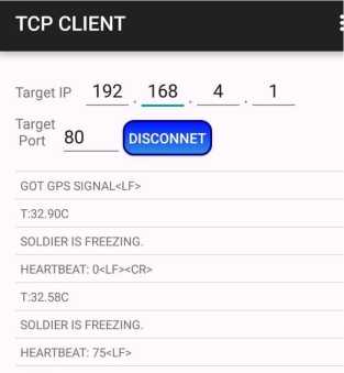
Figure 9.4 Output for heart rate.

Figure 9.5 Output for temperature sensor.
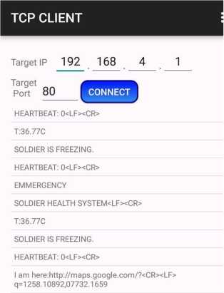
Figure 9.6 Output for panic button.

Figure 9.7 Output for GPS services.
9.6.2 Temperature Sensor
LM35 is a temperature sensor which is widely used to measure body temperature. This device is rated to operate over a –55°C to 150°C temperature range. The normal human temperature is around 370°C [5]. Hence, a threshold value in the range of 300 to 400 C is considered. The output of temperature sensor shown in Figure 9.5.
9.6.3 Panic Button
Panic button is one kind of switch which is provided to soldiers to help in panic situation. If soldier presses panic button, then system will generate an alert by which the base camp will come to know if soldiers are in difficult situation. The output of panic button shown in Figure 9.6.
9.6.4 GPS Receiver
The GPS unit is installed in addressing system so that base camp can track their movements and real-time information in all weather, at all times form anywhere on globe. The output of GPS services shown in Figure 9.7.
9.7 Conclusion
This chapter reports on an IoT-based system for the health monitoring and tracking of soldiers. Biomedical sensors provide heartbeat, body temperature, and environmental parameters of every soldier to control room. This technology can be helpful to provide the accurate location of missing soldier in critical condition and overcome the drawback of soldiers missing in action. The addressing system is also helpful to improve the communication between soldier to soldier in emergency situation and provide proper navigation to control room. Thus, we can conclude that this system will act as a lifeguard to the army personnel of all over the globe. In future, a portable handheld sensor device with more sensing options may be developed to aid the soldiers. In addition to that, Grove gas sensors can be placed which measures oxygen concentration in environment, medical instruction can be given to the soldiers to overcome the situation, and ZigBee technology can be used for extending the range of network for communication.
References
1. Kumar, P., Rasika, G., Patil, V., Bobade, S., Health Monitoring and Tracking of Soldier Using GPS. Int. J. Res. Advent Technol., 2, 4, 291–294, Apr. 2014.
2. Sharma, S., Kumar, S., Keshari, A., Ahmed, S., Gupta, S., Suri, A., A Real Time Autonomous Soldier Health Monitoring and Reporting System Using COTS Available Entities. Second International Conference on Advances in Computing and Communication Engineering (ICACCE), Deharadun-India, pp. 683–687, May 2015.
3. Kumarand, R. and Rajasekaran, M., An IoT based patient monitoring system using raspberry Pi. International Conference on Computing Technologies and Intelligent Data Engineering, Kovilpatti-India, pp. 1–4, Jan. 2016.
4. Jassas, M., Abdullah, A., Mahmoud, H., A Smart System Connecting e-Health Sensors and the Cloud. IEEE 28thCanadian Conference on Electrical and Computer Engineering Halifax, Canada, pp. 712–716, May 2015.
5. Shaikh, R., Real Time Health Monitoring System of Remote Patient Using Arm7. Int. J. Instrum. Control Autom. (IJICA), 1, 3–4, 102–105, 4, 2012.
6. Kumar, D. and Repal, S., Real Time Tracking and Health Monitoring of Soldiers using ZigBee Technology: a Survey. Int. J. Innov. Res. Sci. Eng. Technol., 4, 7, 5561–5574, Jul. 2015.
7. Raj, G. and Banu, S., GPS Based Soldier Tracking And Health Indication System With Environmental Analysis. Int. J. Enhanc. Res. Sci. Technol. Eng., 2, 12, 46–52, Dec. 2013.
- *Corresponding author: [email protected]