14
Communication and Control Systems Implementation in FPGAs and SoCs
In this chapter, you will continue learning about more advanced applications implemented in modern FPGAs and SoCs and what makes these devices suitable to host these types of processing- and bandwidth-demanding applications. You will gain clarity on how pipelined and parallel processing engines required by modern wired and wireless communications systems in general can be easily implemented in the FPGA logic. You will also examine how these parallel compute engines can be interfaced to wide memories and integrated with the powerful CPUs available in the SoCs. You will also gain an overview of modern control and industrial systems, which use a wide range of custom and industry-specific standards. This chapter is also purely informative and introduces high-level architectural details that may inspire you in designing and building these applications. This is the closing chapter of Part 3, which has covered most of the FPGA-based SoC advanced features and advanced applications. It is also the closing chapter of this book; hopefully, by now you have learned enough about the theoretical, architectural, and practical aspects of FPGA-based SoCs. I hope that you are now able to start architecting, designing, and implementing your next SoC-based product.
In this chapter, we’re going to cover the following main topics:
- Communication protocol layers
- Communication protocol layers mapping onto FPGA-based SoCs
- Control systems overview
- Control systems hardware and software mappings onto FPGA-based SoCs
Communication protocol layers
Communication protocols used in electronics systems and the telecommunication industry often follow the Open Systems Interconnection (OSI) model. The OSI model divides the communication protocols into seven layers. These layers are stacked on top of each other and have an abstracted interface through which the communication flows from one layer to the next.
OSI model layers overview
In real implementations, some communication protocols collapse some layers together when it doesn’t make sense to divide the segment of the protocol any lower than the chosen implementation. Also, a communication protocol is often a concatenation of many other protocols that collaborate to map to an OSI communication model. The OSI model layers are as follows:
- Layer 1: Physical layer
- Layer 2: Data Link layer
- Layer 3: Network layer
- Layer 4: Transport layer
- Layer 5: Session layer
- Layer 6: Presentation layer
- Layer 7: Application layer
The Physical layer is the communication medium interface. It is responsible for the packet data conversion into the medium signal format, and transferred over it in the supported format to reach and be understood by the link partner.
The Data Link layer is responsible for interfacing with the network interface. Its main role is to provide the logical links with the network.
The Network layer is a gateway via which the data flow transitions between layers by means of logical addressing and data packet routing.
The Transport layer provides the mechanisms of the data transmission. It controls the data exchange flow and manages errors in the transmission.
The Session layer maintains communication sessions between applications on the connected nodes.
The Presentation layer formats the data stream to transmit and extract data content from the received packets, encrypt and decrypt the data content when applicable, and manage other data formatting (compression and decompression) in use by the protocol.
The Application layer is the communication protocol entry point and provides connectivity options to the software applications for transferring data, control, and messages to another application running on a different node or the same one but behind the Operating System (OS). The following figure illustrates the concept of the layered approach in communication protocols conforming to the OSI model:

Figure 14.1 – Peer-to-peer communication using the OSI model
The Application layer receives the data to transfer to another node from a single source or multiple sources. It then encapsulates it in a format called Protocol Data Unit (PDU), which defines what header and trailer are added to the data. The PDU also defines how long the payload data should be. All these are protocol specific. The communication data is passed from the Application layer through all the intermediate layers to reach the Physical layer, and at each transition, a protocol encapsulation is used when the data crosses the boundary from layer L to layer L-1 in the transmit direction. For the receive direction, a symmetrical path is taken; this time, data is passed from layer L-1 to layer L, and each time the information added from the protocol layer is removed. As mentioned earlier, in certain communication protocols, some layers of the OSI model are merged to simplify the protocol implementation. The Physical layer is responsible for putting data outside of the node on the medium or the link, which will then transfer it to the next node in the communication topology used.
Communication protocols topology
In communication, we can distinguish between peer-to-peer and switched communication topologies. The peer-to-peer topology is the simplest of them all and, as its name implies, it consists of directly connecting two physical nodes. The switched topology connects many nodes in a network and has many nodes and protocols in between the communicating nodes at any given time performing the associated switching operations.
In peer-to-peer communication, the communicating devices are connected directly without any intermediary device, and they exchange data directly through their physical layers over a commonly supported link. The following diagram provides a conceptual view of an OSI model for peer-to-peer communication:

Figure 14.2 – Peer-to-peer communication using the OSI model
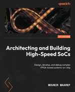
In a switched communication topology, the communicating devices connect to an intermediate device or devices called switching nodes, and they exchange data with the switching nodes. The following diagram provides a conceptual view of an OSI model for a switchable communication protocol:
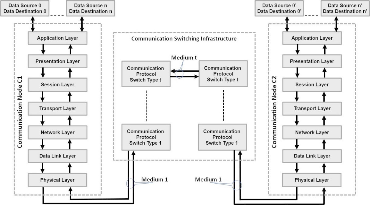
Figure 14.3 – Switchable communication between two nodes using the OSI model
The switching operation may by itself go through many mediums and protocols all abstracted underneath a given layer without the destination node noticing anything about the transformations during the lifetime of the data transfer. This is a huge advantage of following the OSI model recommendation, so whatever transformation the information (packets of data) goes through, the delivered end data to the destination node arrives exactly as it left the initial sending node. Many techniques are used, of course, to guarantee data integrity as it flows from layer to layer and from device to device in the data transit. It is worth noting that not all communication protocols are switchable. However, with the advances in technology, and specifically, the speed at which data can be transferred, protocols are sometimes transported over other protocols that are switchable.
Example communication protocols and mapping to the OSI model
It is probably hard to come up with a communication protocol that offers all the OSI layers in one stack. However, we find that if two or more protocols are grouped together, they can provide a complete mapping of the OSI model. An example is the Transmission Control Protocol and Internet Protocol (TCP/IP), which requires a few more lower layers to make it suitable for communication between two or more physical nodes. The following figure provides a possible mapping between the combination of the TCP/IP suite and the Ethernet protocols to form a full communication stack mapped to the OSI model:

Figure 14.4 – Association of the TCP/IP suite and Ethernet protocols mapping to the OSI model
In this union of protocols association of the TCP/IP suite and the Ethernet protocol, we can achieve a full communication stack capability with the possibility of exchanging data between two physical nodes. The physical nodes can be connected on a peer-to-peer topology or via a switched network that can by itself be of many types.
Communication protocol layers mapping onto FPGA-based SoCs
In the last example, where the TCP/IP protocol suite was associated with the Ethernet protocol to provide a full OSI model communication stack, another mapping can be performed, but this time to implement the model on a real solution. If we take the Zynq-7000 SoC FPGA, we can have the possible mappings illustrated in the following figure:
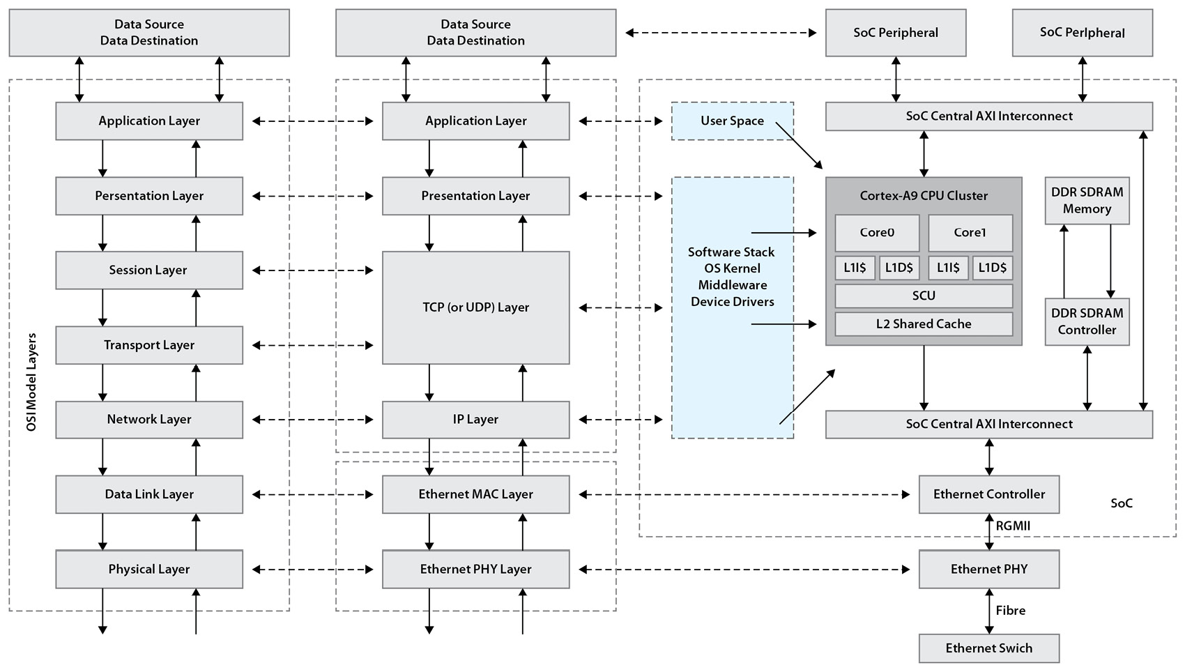
Figure 14.5 – Mapping of the full communication stack to the Zynq-7000 SoC
In this mapping, the source of the data to transmit from the SoC and the destination of the data received from the communication stack can be the SoC peripherals. In a Closed-Circuit Television (CCTV) application, data in the form of a video stream can be collected from a digital camera, processed, and then transmitted over TCP/IP. The SoC is connected to the Local Area Network (LAN) to which the security central command room is also connected with control computers and digital display units. The video stream collected by the security camera is fed to the SoC via a video interface. It is then digitally processed within the SoC and only data of interest is streamed over the network. The video data is passed from the camera to a user application where some algorithmic processing is performed on it. Once ready, the data is then packetized and passed to a kernel module performing encryption and compression on it either in software or using the Programmable Logic (PL) accelerators. The kernel module then calls the OS networking services over a TCP/IP connection when data packets are ready to transmit. When the OS schedules the data for connection, it calls the middleware stack to perform the data transfer on behalf of the initial user application. Data is processed serially by the TCP layer and then passed over to the IP layer, which adds the destination information and then puts it in a queue. It then sends the request to the OS to perform another call to the Ethernet drivers to pass the data in as an Ethernet frame to the Ethernet MAC. The Ethernet MAC serializes the data, performs all the required operations on it, and then streams it over the RGMII interface to the Ethernet PHY. The Ethernet PHY is just a medium translator that takes logical information and transforms it into lights to be transmitted over fiber to the Ethernet LAN switch. When data is received from the network and its destination is the SoC, a symmetrical mechanism is performed on it starting from the Ethernet PHY all the way to the destination user application that will consume it as programmed to do so. Data received by the Zynq-7000 SoC FPGA from the security central command via the Ethernet interface and the TCP/IP stack running on the Cortex-A9 can be a motor control command for camera tracking, image filters update information, and so on.
Control systems overview
Control systems in this context refer to the industrial control systems known as Programmable Logic Controllers (PLCs). PLCs classically performed a set of control operations by actioning certain responses because of a captured input stimulus. They are industrial computing engines packaged appropriately to operate in harsh environments. They are used to control assembly lines in manufacturing, robots, general machinery, and high-reliability operations. They have a relatively simple programming interface and a high capability of detecting and dealing with operational faults. PLCs have been around since the 1960s when they were first introduced in the automobile industry in the United States. From an architecture perspective, a PLC is simply a microprocessor-based controller for industrial applications with storage memory for hosting the executable application to run on it. A PLC includes the following:
- A Central Processing Unit (CPU)
- A Power Supply Unit (PSU)
- A Memory Unit (MU)
- Input and Output (IO) Interfaces
- Communications Interfaces (CIs)
The CPU receives input from its operating environment via a set of interfaces. It performs on the input the necessary computational operations as indicated by the control program stored in the PLC memory and generates the corresponding results. These results are sent through its output interfaces.
The Power Supply Unit (PSU) converts the Alternate Current (AC) to a Direct Current (DC) power source for the PLC unit.
The MU stores data to operate on from the input interfaces and the program to be executed by the CPU.
The IOs are the interfaces via which the controller communicates with its direct environment, and via which it receives the stimulus and provides the data to the neighboring devices within the operating environment.
The CIs are the remote communication interfaces via which the PLC transmits and receives data, usually through industrial networks such as industrial Ethernet.
Information
For more information about the history of PLCs, please check out the following white paper: https://www.c3controls.com/white-paper/history-of-programmable-logic-controllers/
PLC programming devices are used to develop and download the PLC executable program into the MU of the controller. In general, there is a Real-Time Operating System (RTOS) running on the PLC CPU and managing the different software threads implementing the PLC control program. The following figure provides an architectural overview of modern PLCs:
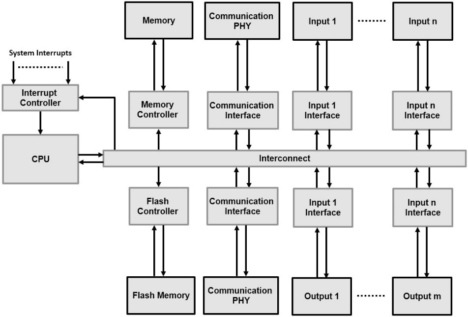
Figure 14.6 – PLC industrial controller architecture overview
With the advance in technology and industry standards, PLCs have also seen an evolution in their role and an expansion into other domains and applications, as we will cover in the next section.
Control system hardware and software mappings onto FPGA-based SoCs
Modern PLCs are intelligent nodes deployed in the Edge and can have versatile and customizable added functionality. PLCs run software that conforms to the IEC 61131 standard, but expanding their functionality into parallel operations, such as image processing, network filtering, and other Digital Signal Processing (DSP) acceleration, is a desirable added value. The Zynq-7000 SoC provides all the features that are required to build a base PLC industrial controller starting from its PS based on the Cortex-A9 CPU cluster, with its rich peripherals set and the necessary memories and memory interfaces. Its high-throughput interfaces to the associated PL make the functionality expansion an interesting solution in a single chip.
FPGA logic and DSP resources can be used to build computational engines to perform many expansion functions, as well as building custom IOs and communication interfaces that are specific to industrial applications and not available in the PS block. To enhance the PLC based on FPGA SoCs, we can list the following:
- Maintenance operations alerts
- Local DSP algorithm implementation, avoiding data transfers over the network to a central compute node
- Communication protocol acceleration, such as packet filtering and data encryption/decryption
- Fast and deterministic control loop implementation based on hardware state machines
- Image signal processing acceleration
- Software application isolation
It is also worth noting that the design tools used to build the hardware and software for safety-critical operations needs to be certified, which is the case for the Xilinx tools used now for many decades in industrial applications such as PLCs. The following diagram provides a simple mapping for the PLC architecture with the expansion capabilities in FPGA-based SoCs such as the Zynq-7000 SoC:

Figure 14.7 – Example extensible PLC controller architecture mapped to the Zynq-7000 SoC
As can be seen in the previous diagram, a PLC based on an FPGA SoC such as the Zynq-7000 SoC has all the required hardware elements, either as hard IPs within the PS or custom IPs to be added from within the PL. This single-chip solution is an attractive option for modern PLCs, which can be implemented with advanced intelligence and computation capabilities.
Summary
In this closing chapter of Part 3 and this book, we looked at some more advanced applications where FPGA-based SoCs are well suited as a single-chip architecture. They offer a fast time-to-market product development, a lower product cost, and a lower power solution in comparison to multi-chip-based architectures. These advanced applications include sophisticated communication applications that follow the OSI model, or part of it. They also span industrial control applications such as modern PLCs with advanced computation capabilities and feature extensibility using the FPGA PL and DSP computation engines. As we examined in detail in this book, SoCs built using PL have optimal integration and interoperability between the Cortex-A9 CPU cluster and the PL. This flexible architecture offers many capabilities for building communication applications that benefit from the acceleration and filtering extensions that can be hosted in the FPGA logic. PLCs also require more at the Edge processing and intelligence, which is customized to enhance the solution and adapt it to potentially evolving and changing operational environments and conditions.
Part 3 of this book covered some advanced and complex aspects of SoC architecture development and design, including advanced accelerator integration using the Cortex-A9 ACP port and software development using an RTOS. It also addressed the architectural design and system capabilities of video processing, communication protocol implementation, and control system design using FPGA-based SoCs such as the Zynq-7000 SoC devices.
This book covered topics related to SoC architecture design, provided detailed implementation examples targeting the Zynq-7000 SoC FPGA, and made good use of the Xilinx implementation tools. After reading it, if necessary many times, you should be ready to put the skills learned into practice in architecting and building your next SoC, having a high degree of confidence in your product’s success.
Good luck!
Questions
Answer the following questions to test your knowledge of this chapter:
- What is the OSI model? How useful is it if its recommendation is followed when defining a protocol specification?
- List the OSI model layers and provide a brief description of each layer.
- What are the main topologies of communication systems? What is the difference between them?
- To conform to the OSI model, should a communication protocol implement all the OSI model layers?
- Is TCP/IP a communication protocol that can map directly to the OSI model? Which layers are missing?
- Which other communication protocol can be appended to the TCP/IP protocol to form a protocol suite that fully implements the OSI model?
- Which layers of the preceding protocol association can be mapped to the Zynq-7000 SoC FPGA, and which layers need to be implemented using software?
- What are PLCs and where were they initially used?
- What are the main elements of a PLC architecture?
- What are some of the extra functionalities that modern PLCs require to become more attractive and add extra interesting features?
- How can the FPGA SoC provide the optimal platform to build a modern and intelligent PLC?