
So now we have developed our mood lamp, but it will turn on only when we connect a power supply to Arduino. It won't turn on or off depending on the darkness of the environment. Also, to turn it off, we have to disconnect our power supply from Arduino. In this section, we will learn how to use switches with Arduino.
Switches are one of the most elementary and easy-to-overlook components. Switches do only one thing: either they open a circuit or short circuit. Mainly, there are two types of switches:
Normally, all the switches are NO (normally opened) type switches. So, when the switch is actuated, it closes the path and acts as a perfect piece of conducting wire. Apart from this, based on their working, many switches are out there in the world, such as toggle, rotary, DIP, rocker, membrane, and so on.
Here, we will use a normal push button switch with four pins:
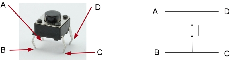
In our push button switch, contacts A-D and B-C are short. We will connect our circuit between A and C. So, whenever you press the switch, the circuit will be complete and current will flow through the circuit. We will read the input from the button using the digitalRead() function. We will connect one pin (pin A) to the 5 V, and the other pin (pin C) to Arduino's digital input pin (pin 2). So whenever the key is pressed, it will send a 5 V signal to pin 2.
We will add a few more things in the mood lamp we discussed to make it more robust and easy to use. Along with the switch, we will add some kind of light-sensing circuit to make it automatic. We will use a Light Dependent Resistor (LDR) for sensing the light and controlling the lamp.
Basically, LDR is a resistor whose resistance changes as the light intensity changes. Mostly, the resistance of LDRs drops as light increases. For getting the value changes as per the light levels, we need to connect our LDR as per the following circuit:
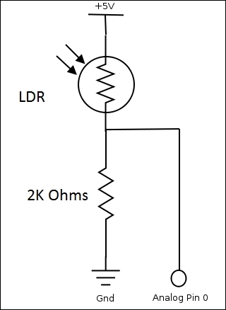
Here, we are using a voltage divider circuit for measuring the light intensity change. As light intensity changes, the resistance of the LDR changes, which in turn changes the voltage across the resistor. We can read the voltage from any analog pin using analogRead().
Once you have connected the circuit as shown, write the following code in the editor:
int LDR = 0; //will be getting input from pin A0
int LDRValue = 0;
int light_sensitivity = 400;    //This is the approx value of light surrounding your LDR
int LED = 13;

void setup()
{
  Serial.begin(9600);          //start the serial monitor with 9600 buad
  pinMode(LED, OUTPUT);

}

void loop()
{
  LDRValue = analogRead(LDR);     //Read the LDR's value through LDR pin A0
  Serial.println(LDRValue);       //Print the LDR values to serial monitor

  if (LDRValue < light_sensitivity)
  {
    digitalWrite(LED, HIGH);
  }
  else
  {
    digitalWrite(LED, LOW);
  }
  delay(50);        //Delay before LDR value is read again
}
In the preceding code, we are reading the value from our LDR at pin analog A0. Whenever the value read from pin A0 is below a certain threshold value, we are turning on the LED. So whenever the light (lux value) around the LDR drops, then the set value, it will turn on the LED, or in our case, the mood lamp.
Similarly, we will add a switch in our mood lamp to make it fully functional as a pixar lamp.
Connect one pin of the push button at 5 V and the other pin to digital pin 2. We will turn on the lamp only, and only when the room is dark and the switch is on. So we will make the following changes in the previous code.
In the setup function, initialize pin 2 as input, and in the loop add the following code:
buttonState = digitalRead(pushSwitch); //pushSwitch is initialized as 2.
If (buttonState == HIGH){

//Turn on the lamp
}
Else {
//Turn off the lamp.
//Turn off all LEDs one by one for smoothly turning off the lamp.
  for(redValue = 255; redValue > 0; redValue--){
    analogWrite(redLed,redValue);
    analogWrite(greenLed,greenValue);
    analogWrite(blueLed,blueValue);
    delay(10);
  }
  for(greenValue = 255; greenValue > 0; greenValue--){
    analogWrite(redLed,redValue);
    analogWrite(greenLed,greenValue);
    analogWrite(blueLed,blueValue);
    delay(10);
  }
  for(blueValue = 255; blueValue > 0; blueValue--){
    analogWrite(redLed,redValue);
    analogWrite(greenLed,greenValue);
    analogWrite(blueLed,blueValue);
    delay(10);
  }
}
So, now we have incorporated an LDR and switch in our lamp to use it as a normal lamp.