
LED strips are flexible circuit boards with full color LEDs soldered on them. There are two basic types of LED strip: the "analog" and "digital" kinds. Analog strips have all the LEDs connected in parallel. So, they act as one huge tri-color LED. In case of an analog LED strip, we can't set the color/brightness of each LED. So, they are easy to use and inexpensive. Digital LED strips work in a different way. To use the LED, we have to send digital code corresponding to each LED in the case of a digital LED strip. As they provide more modularity, they are quite expensive. Also, digital LED strips are difficult to use compared to analog LED strips:
Internally, RGB LEDs are connected to each other in parallel. One section of the strip contains all three LEDs, connected in parallel. A complete LED strip is made up of a number of parallel RGB LEDs connected in series. Connection in one block/section is as shown in the following figure:
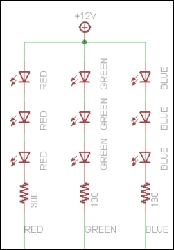
As one section contains multiple LEDs, it requires more current to run. It can't run on the current provided from Arduino. In case of full white, each segment will require approximately 60 mA of current per block/section. So to run the complete LED strip, we may require current of up to 1.2 A per meter. For running an LED strip, an external power supply of 12 V is required.
As we know, we can draw maximum current up to 300 mA if we put all the I/O pins together. But, as we require a higher current, we will have to use an external power supply. Now here comes the tricky part. We will use Arduino to control the LED strip, and for a power supply, we will use external power. For connecting the LED strip with Arduino, we will use MOSFET to limit the current drawn to and from Arduino.
Here, we will use N-channel MOSFET, which is very inexpensive and works with 3.3 V to 5 V logic. These FETs can switch over 60 A and 30 V.
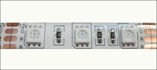
Connecting to the strip is relatively easy. We need to solder the wires to the four pins/copper pads of our LED strip. One can use heat shrink for providing insulation, abrasion resistance, and environmental protection.
To use our LED strip with Arduino, we will require some resistors as well, to limit the current:
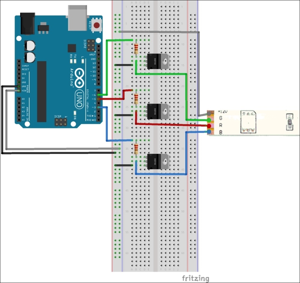
Connect the power transistor with the resistor in between the PWM output pin and the base. In case of NPN transistors, pin 1 is the base. Pin 2 is the collector and pin 3 is the emitter. Now, for power supply to Arduino and the LED strip, connect a 9 -12 V power supply to the Arduino, so that Vin supplies the high voltage to the LED.
At the end of the wiring connection, make sure to connect the ground of the supply to that of Arduino/MOSFETs. Connect the Arduino output pin to the base of the MOSFET (pin 1) with a 100-220 Ω resistor in between. Connect pin 2 of the MOSFET to the LED strip's input pin and connect pin 3 of the MOSFET to the ground.
Check all the connections and write the following code in the editor window of Arduino. Here, we are using pins 5, 6, and 3 of Arduino to control the LED strip's red, green, and blue LEDs respectively:
int redLed = 5;
int greenLed = 6;
int blueLed = 3;

int redValue   = 0;
int greenValue = 0;
int blueValue  = 0;

void setup(){
  randomSeed(analogRead(0));
}

void loop() {
  redValue = random(0,256); // Randomly generate 1 to 255
  greenValue = random(0,256); // Randomly generate 1 to 255
  blueValue = random(0,256); // Randomly generate 1 to 255

  analogWrite(redLed,redValue);
  analogWrite(greenLed,greenValue);
  analogWrite(blueLed,blueValue);

// Incrementing all the values one by one after setting the random values.
  for(redValue = 0; redValue < 255; redValue++){
    analogWrite(redLed,redValue);
    analogWrite(greenLed,greenValue);
    analogWrite(blueLed,blueValue);
    delay(10);
  }
  for(greenValue = 0; greenValue < 255; greenValue++){
    analogWrite(redLed,redValue);
    analogWrite(greenLed,greenValue);
    analogWrite(blueLed,blueValue);
    delay(10);
  }
  for(blueValue = 0; blueValue < 255; blueValue++){
    analogWrite(redLed,redValue);
    analogWrite(greenLed,greenValue);
    analogWrite(blueLed,blueValue);
    delay(10);
  }

  //Decrementing all the values one by one for turning off all the LEDs.
  for(redValue = 255; redValue > 0; redValue--){
    analogWrite(redLed,redValue);
    analogWrite(greenLed,greenValue);
    analogWrite(blueLed,blueValue);
    delay(10);
  }
  for(greenValue = 255; greenValue > 0; greenValue--){
    analogWrite(redLed,redValue);
    analogWrite(greenLed,greenValue);
    analogWrite(blueLed,blueValue);
    delay(10);
  }
  for(blueValue = 255; blueValue > 0; blueValue--){
    analogWrite(redLed,redValue);
    analogWrite(greenLed,greenValue);
    analogWrite(blueLed,blueValue);
    delay(10);
  }
}
If everything is in place, you should be able to see the LED strip getting on and changing its color.
Now we have learned about all the things required to control the TV backlight using IR remote, so we will integrate all the things that we learned in this chapter:
- How IR works
- How to read values from an IR remote
- How to control an LED strip
We want to control the brightness of the LED strip as well. We will use the power button to turn the backlight off and on. With volume plus and volume minus, we will increase and decrease the brightness of the backlight.
As we did earlier in the chapter, connect TSOP38238 to pin 11, 5 V, and ground pin of Arduino. Once you have done all the connections, upload the following code on Arduino:
#include <IRremote.h>
const int IR_RECEIVER = 11; // Connect output pin of TSOP38238 to pin 11
IRrecv receiver(IR_RECEIVER);
decode_results buttonPressed;
long int buttonValue = 0;

// Mention the codes, you get from previous exercise
const long int POWER_BUTTON = 54572; // Power button to turn on or off the backlight
const long int PLUS_BUTTON = 54536;  // Increase brightness of the LED Strip
const long int MINUS_BUTTON = 54608; // Decrease brightness of the LED strip
const long int CHANGE_COLOR = 54584; // Decrease brightness of the LED strip

const int FADE_AMOUNT = 5; // For fast increasing/decreasing brightness increase this value
boolean isOn = false;

int redLed = 5;
int greenLed = 6;
int blueLed = 3;

int redValue   = 0;
int greenValue = 0;
int blueValue  = 0;

int colors[3];

// Power up the LED strip with random color
void powerUp(int *colors)
{
  redValue = random(0, 256); // Randomly generate 1 to 255
  greenValue = random(0, 256); // Randomly generate 1 to 255
  blueValue = random(0, 256); // Randomly generate 1 to 255

  analogWrite(redLed, redValue);
  analogWrite(greenLed, greenValue);
  analogWrite(blueLed, blueValue);

  colors[0] = redValue;
  colors[1] = greenValue;
  colors[2] = blueValue;
}

// Turn off the LED
void powerDown(int *colors)
{
  redValue = colors[0];
  greenValue = colors[1];
  blueValue = colors[2];

  //Decrementing all the values one by one for turning off all the LEDs.
  for (; redValue > 0; redValue--) {
    analogWrite(redLed, redValue);
    delay(10);
  }
  for (; greenValue > 0; greenValue--) {
    analogWrite(greenLed, greenValue);
    delay(10);
  }
  for (; blueValue > 0; blueValue--) {
    analogWrite(blueLed, blueValue);
    delay(10);
  }
  colors[0] = redValue;
  colors[1] = greenValue;
  colors[2] = blueValue;
}

void increaseBrightness(int *colors)
{
  redValue = colors[0];
  greenValue = colors[1];
  blueValue = colors[2];

  redValue += FADE_AMOUNT;
  greenValue += FADE_AMOUNT;
  blueValue += FADE_AMOUNT;

  if (redValue >= 255) {
    redValue = 255;
  }

  if (greenValue >= 255) {
    greenValue = 255;
  }

  if (blueValue >= 255) {
    blueValue = 255;
  }
  analogWrite(redLed, redValue);
  analogWrite(greenLed, greenValue);
  analogWrite(blueLed, blueValue);

  colors[0] = redValue;
  colors[1] = greenValue;
  colors[2] = blueValue;
}

void decreaseBrightness(int *colors)
{
  redValue = colors[0];
  greenValue = colors[1];

  blueValue = colors[2];

  redValue -= FADE_AMOUNT;
  greenValue -= FADE_AMOUNT;
  blueValue -= FADE_AMOUNT;

  if (redValue <= 5) {
    redValue = 0;
  }

  if (greenValue <= 5) {
    greenValue = 0;
  }

  if (blueValue <= 5) {
    blueValue = 0;
  }
  analogWrite(redLed, redValue);
  analogWrite(greenLed, greenValue);
  analogWrite(blueLed, blueValue);

  colors[0] = redValue;
  colors[1] = greenValue;
  colors[2] = blueValue;
}

// Randomly generates a color and make a smooth transition to that color
void changeColor(int *colors)
{
  int newRedValue = random(0, 256); // Randomly generate 1 to 255
  int newGreenValue = random(0, 256); // Randomly generate 1 to 255
  int newBlueValue = random(0, 256); // Randomly generate 1 to 255

  redValue = colors[0];
  greenValue = colors[1];
  blueValue = colors[2];

  if (newRedValue > redValue) {
    for (; redValue >= newRedValue; redValue++) {
      analogWrite(redLed, redValue);
      delay(10);
    }
  }
  else {
    for (; redValue <= newRedValue; redValue--) {
      analogWrite(redLed, redValue);
      delay(10);
    }
  }

  if (newGreenValue > greenValue) {
    for (; greenValue >= newGreenValue; greenValue++) {
      analogWrite(greenLed, greenValue);
      delay(10);
    }
  }
  else {
    for (; greenValue <= newGreenValue; greenValue--) {
      analogWrite(greenLed, greenValue);
      delay(10);
    }
  }

  if (newBlueValue > blueValue) {
    for (; blueValue >= newBlueValue; blueValue++) {
      analogWrite(blueLed, blueValue);
      delay(10);
    }
  }
  else {
    for (; blueValue <= newBlueValue; blueValue--) {
      analogWrite(blueLed, blueValue);
      delay(10);
    }
  }

  colors[0] = redValue;
  colors[1] = greenValue;
  colors[2] = blueValue;
}

void setup() {
  Serial.begin(9600);
  receiver.enableIRIn(); // Start the receiver

  randomSeed(analogRead(0));

  pinMode(redLed, OUTPUT);
  pinMode(greenLed, OUTPUT);
  pinMode(blueLed, OUTPUT);
}

void loop() {

  if (receiver.decode(&buttonPressed))
  {
    buttonValue = buttonPressed.value;
    Serial.println(buttonValue);
    switch (buttonValue) {
      case POWER_BUTTON:
        if (!isOn) {
          powerUp(colors);
          isOn = true;
        }
        else {
          powerDown(colors);
          isOn = false;
        }
        break;
      case PLUS_BUTTON:
        decreaseBrightness(colors);
        break;
      case MINUS_BUTTON:
        increaseBrightness(colors);
        break;
      case CHANGE_COLOR:
        changeColor(colors);
        break;
      default:
        Serial.println("Waiting for input. ");
    }
    receiver.resume(); // Receive the next value
  }
  delay(100);
}
In the preceding code, we are using the power button to turn the backlight on and off, and the volume up and down buttons to increase and decrease the brightness respectively. I have used the up arrow button to change the color of the strip. You can add more features to this project by configuring it in the switch case block.