
An LED matrix is also known as a diode matrix, referring to the LED's one-directional polarity. An LED matrix is a two-dimensional grid with an LED connected to each intersection where a row crosses a column. The columns and rows are isolated from one another in order for the matrix to work. In electronics this is also known as multiplexing.
Figure 3.3 illustrates the entire schematic of all the connections. To the right, you will find the matrix layout. All the negative sides of the LEDs are connected in rows and all the positive sides of the LEDs are connected in columns. When power is applied to one of the columns, and a ground connection is opened up on the negative rows, only one LED will light up. As you might have noticed, we have connected part of the matrix to the analog pins. Since there are not enough digital pins, we will use some of the analog pins instead. The analog pins can be operated as digital pins and their numbering continues on from pin 13. In other words, analog pin A1 is the same as digital pin 14, and so on.
As I said before, the current can only pass through an LED in one direction, a fact we are using to our benefit while creating the LED matrix, giving us the possibility of controlling many LEDs with fewer pins. If we did not connect everything in a matrix, we would need 30 pins in order to control all the LEDs separately. The downside of using a matrix configuration is that we can only control one LED at a time.
However, we will take advantage of another phenomenon called POV (persistence of vision). POV is a term used to describe an optical illusion where multiple images blend into one image in the mind of the beholder. The brain can only interpret about 25 discreet images per second; any more than that and the images start to blend together.
The following Figure 3.3 illustrates the entire schematic of all the connections:

Figure 3.3: The matrix schematic
Arduino is fast, even faster than the human eye, so we will use this speed to our advantage in order to give the impression of lighting up many LEDs at the same time. As I said, we can't technically light up more than one LED at once in the matrix but we can switch between them so fast that the human eye will perceive it as more than one LED being on. But before we get to this part, we need to connect everything, and this means it is time to turn on the soldering iron.

Figure 3.4: Showing all the LEDs lined up for soldering
Before we start soldering, we need to place the LEDs in the right order. A good idea is to check that all your LEDs work before soldering them. By connecting the LEDs one by one to a 3.3V coin cell battery, or using the power that goes from your Arduino to a breadboard, you can easily do this. If you are using a breadboard, don't forget to add a 220Ω resistor.
If you cut 5 mm holes, the LEDs should fit nicely. If they are a bit loose don't worry, as once they are soldered together everything will be held in place. To create the matrix, we need to solder the LEDs into rows and columns. In Figure 3.4 you can see how I have prepared the LEDs for soldering by bending the legs of the LEDs into the desired rows and columns. All the negative legs (the shorter ones) will be soldered in horizontal lines, and then the positive legs (the longer ones) will be soldered in vertical lines. Make sure that you bend the positive lines over the negative lines so they do not come into contact with one another. If they do, the matrix will not work as it is supposed to. If you want, you can cover up your lines using some tape needed. This is done by placing a small piece of tape in between the legs of the LEDs so they do not touch one another.
Once you are done, we can move on and add the wiring and the resistors that will connect to our Arduino board. Figure 3.5 shows a close-up of the resistors connected straight to the positive column in the glasses, and the wires connected to the other side of the resistors. The idea is to place the Arduino board on the inside of either the left or right frame. Before you cut your wires, measure the distance between the row and the location of the Arduino board where it will be placed on the inside of the side frame. Make sure you add some extra length before you cut them because it is better to have wires that are too long than too short.
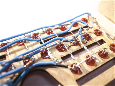
Figure 3.5: A close-up of the matrix
Now is also a good time to put the JST female connector in place as shown in Figure 3.6. JST connectors are fairly standard connector for batteries, and in this project we will be using a very small 3.7V battery with a male JST connector. You can place the JST connector anywhere you like, but I found a good spot where the front panel meets the frame just under the supporting piece of MDF. Make sure you leave enough space on the back side of the connector to fit the power cable that connects to the Arduino board. To keep the JST connector in place, use some glue:

Figure 3.6: The JST female connector in place
When you have added the wires to all the positive columns, you can add three cables for the negative rows, again ensuring you make them long enough to reach the Arduino board. You don't need resistors on these lines since these will act as our GND channels.
Once you have all the LEDs, resistors, and wires in place, it is time to connect everything to the Arduino board. In this chapter, we are using the Trinket board from Adafruit, but you could also use an Arduino micro board, which is very similar in size. These boards are some of the smallest Arduino boards that offer most of the functionality of a standard Arduino board.
Soldering all the wires in place might be tricky. I started by gluing the board to the inside of the frame and then soldering the wires one by one. I would suggest that you place them where they fit best. You can always switch the layout in the code later on. In Figure 3.7 you will see what it might look like once all the wires are connected:
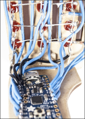
Figure 3.7: The Trinket board in place
Take your time soldering all the wires in place. I admit that even someone with good soldering skills might find this project a bit tricky since it requires some unconventional soldering. I call this type of solder action "soldering" since you usually end up with something that looks like it came from a movie. Usually, you solder components on a flat surface, but with wearable projects like this one you need to be a bit creative when it comes to soldering things together. Eventually you will end up with an inside that is as impressive as the outside.
Next, we will move on to the programming side, and this is where we get to see the glasses in action. For the programming part, we will power the glasses via the USB cable, and once we are done we will add a battery, then you will be ready to head out into the night to impress everyone.