With use cases, you can keep concerns separate during requirements time, but that is not enough. You also need to preserve that separation during design and implementation. In this chapter, we look at a particular kind of use case called a peer use case. Peer use cases have no relationship with one another, but their realizations involve the participation of some shared classes. You may find that some classes and some parts of classes are shared and reusable across use cases, while others are specific to each use-case realization. A use-case slice modularizes the specifics of a use case in a model. It utilizes aspects as a composition mechanism to extend use-case-specific features (attributes, relationships, and operations) onto these shared classes.
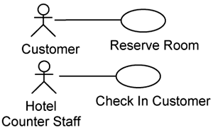
From a use-case modeling perspective, peer use cases have no relationships (i.e., inclusion, extension, or generalization) between them. When attempting to realize peer use cases, you find that they impact the same classes, which is why they are called peers. The Reserve Room and Check In Customer use cases, as shown in Figure 8-1, are examples of peer use cases for the Hotel Management System. These two use cases affect the Room class, as we shall see in a minute.
The fact that there are no relationships between peer use cases means that it is possible to get different persons to detail peer use cases separately and in parallel. Some coordination definitely is required, since their authors have to use the same vocabulary. When you start to realize peer use cases, you want to work on them separately and in parallel.
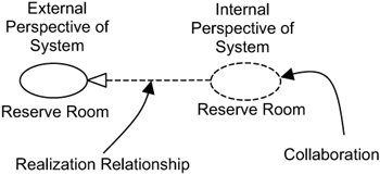
The realizations of use cases are modeled using collaborations. Use cases describe a system from the external perspective—how actors interact with the system. Use cases do not describe a system’s internals—how classes within the system collaborate to realize the use case. The internals are modeled by collaborations. A collaboration defines a set of class instances that cooperate to achieve a given task. The task can be the realization of a use case or the realization of an infrastructure mechanism, and so on. Thus, use cases and collaborations are two sides of a coin—the use case describes the system from the external perspective and the collaboration describes the system from an internal perspective. Figure 8-2 depicts the relationship between the Reserve Room use case and its realization modeled as a collaboration. UML denotes a collaboration as a dashed ellipse icon containing the name of the collaboration, and the dashed arrow with a triangle arrowhead in Figure 8-2 denotes the realization relationship in UML.
A collaboration identifies different roles classes play to realize a use case. The collaboration demands a number of features (i.e., attributes, operations, and relationships) on classes that play these roles. For example, the Reserve Room use-case realization (see Figure 8-3) requires a class to play the role of the resource being reserved. This role is fulfilled by the Room class. Assuming that the Room class at this moment has no such features, you have to extend (i.e., add onto) the Room class with the two required operations updateAvailability() and retrieve().
A class extension is a modular extension to an existing class to play the role identified by a collaboration (use-case realization). Sometimes, you do not need to add complete operations into the existing class. Instead, you might need only to extend an existing operation with some behaviors to play the role identified by the collaboration. This modular extension to an existing operation is known as an operation extension.
When you realize a use case, you identify classes that participate in the realization and the required roles thereafter expressed as features of these classes. You do this by walking through the use-case specifications, and at each step of a use-case flow, determining the classes you need. In the case of the Reserve Room use-case realization, we have identified two classes: the ReserveRoomHandler class and the Room class. Regarding the Reserve Room collaboration, the classes ReserveRoomHandler and Room play two different roles.
The
ReserveRoomHandlerclass plays the role of a controller. It coordinates other classes in the realization of the Reserve Room use case. In particular, it has amakeReservation()operation to coordinate the actions to make a reservation.The
Roomclass plays the role of a resource that can be reserved. It is responsible for retrieving and updating information about the room’s availability.
In reality, more classes are involved (e.g., a Reservation class), but for simplicity, we restrict our discussion to just these two classes. We deal with more complex examples in the next part of the book. In addition, the classes ReserveRoomHandler and Room may play other roles in other collaborations (i.e., use-case realizations).
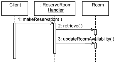
You identify the features required for each class by walking through each step of a use-case description and determining how a particular class instance invokes another class instance. This can be represented using interaction diagrams such as that depicted in Figure 8-4. An interaction diagram depicts the chronological ordering from one class instance to another class instance.
Figure 8-4 shows the sequence of actions that occur when some client invokes the makeReservation() operation on a ReserveRoomHandler instance. The ReserveRoomHandler instance retrieves details of rooms and updates their availability accordingly. This is achieved by calling two operations on a Room instance: retrieve() and updateAvailability().
Once you have identified the required features of each class, you present them in a collaboration, as shown in Figure 8-5. The roles played by the ReserveRoomHandler and Room classes are denoted by labels on the ends of the solid lines (known as associations in UML) joining the collaboration and the class extensions in Figure 8-5.
In Figure 8-5, each class extension identifies only a subset of a class’s features. Consider the Room class extension. It identifies only the operations updateAvailability() and retrieve(). The complete Room class will have other operations. The final Room class is a composition of all Room class extensions over all use-case realizations.
Figure 8-5 shows only operations in class extensions. In general, a collaboration identifies other kinds of features in a class extension, such as attributes and relationships. You identify these similarly to the way you identify operations. So, it suffices for us to limit our discussion to operations throughout this chapter. We want to keep the discussion simple.
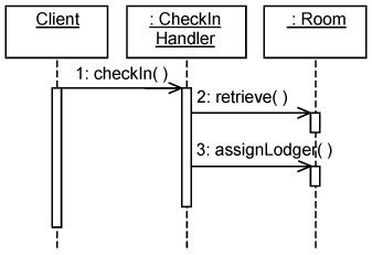
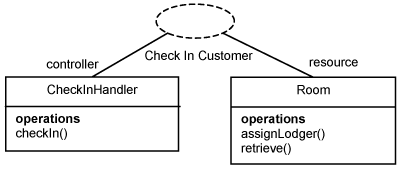
To illustrate how the realization of peer use cases overlaps, we need the help of another use-case realization—the realization of the Check In Customer use case. It involves a new CheckInHandler class, which plays the role of a controller and the same Room class we had earlier. The interaction between these classes when a client invokes the checkIn() operation on a CheckInHandler instance is illustrated in Figure 8-6.
When a client invokes the checkIn() operation on a CheckInHandler instance, the latter retrieves details of rooms and assigns a lodger to the room. This is achieved by invoking two operations on a Room instance: retrieve() and assignLodger().
The roles played by the classes and the operations required by the Check In Customer use-case realization are summarized in Figure 8-7.
Consider the realization of the two use cases above—Reserve Room and Check In Customer. You find that the roles in the Check In Customer collaboration and those in the Reserve Room collaboration are the same. This, however, does not constitute overlap, since these roles belong to different collaborations. This is analogous to two classes having some attributes with the same name. It is legal, and it does not constitute an overlap.
The two use-case realizations require classes that are specific to them, such as ReserveRoomHandler and CheckInHandler. They require classes that are shared—the Room class—which constitutes overlap (i.e., overlapping classes). In addition, the retrieve() operation needed in the Room class extension is used in both collaborations—this also constitutes overlap (i.e., overlapping operations).
In the absence of aspect orientation, a developer today would collate the extensions for each class before implementing the class itself. Some of these classes would be existing classes, and he or she would add the new features into them. Some of these would be new classes that have not been previously identified, and the developer would need to create them in the correct package in the design model. This, as we all know, leads to scattering of the use-case realization and tangling of classes. You need to keep the specifics of a use-case realization separate, which we demonstrate in the next section.
To preserve the modularity of use cases during their realization in a model, a new modularity unit is needed to contain the elements (and extensions of elements) that are specific to the use-case realization. We call this modularity unit a use-case slice because its contents are for a specific use case and it cuts, or slices, across a model (the design model in this case.)
A use-case slice contains the following:
For each use case, there will be a use-case slice in the design model. Thus, for the Reserve Room use case, there is a corresponding Reserve Room use-case slice. The Reserve Room use-case slice contains the following:
Collaboration. The collaboration contains a set of diagrams (interaction diagrams, class diagrams, etc.) that describe how the Reserve Room is realized.
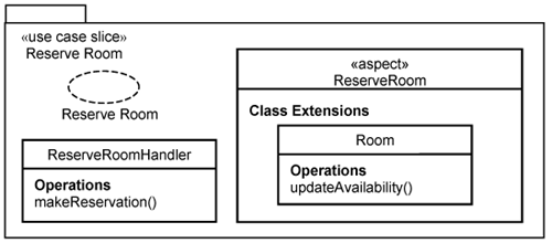
Specific Classes. The
ReserveRoomHandlerclass is specific to this use-case realization and is not needed in the Check In Customer use-case realization.Specific Extensions. The
Roomclass is needed by several use-case realizations. However, theupdateAvailability()is specific to the Reserve Room use-case realization. This is defined within a class extension in the use-case slice.
The retrieve() operation is required by different use-case realizations and is defined in some other lower use-case slice (such as that for included use case or a generalized use case) or a non-use-case-specific slice. We discuss them in subsequent sections.
Figure 8-8 depicts the Reserve Room use-case slice. It is a special kind of package and is stereotyped as «use case slice». You normally name a use-case slice with the same name as its corresponding use case. The collaboration it contains is named the same way.
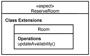
The Reserve Room use-case slice contains a class ReserveRoomHandler and a Room class extension. You need a mechanism to compose the Room class fragment into the existing Room class. This is achieved using aspects in AOP. We model aspects as an element stereotyped «aspect». It represents our proposed UML construct for modeling aspects. Aspects have a class extensions compartment to overlay class extensions onto existing classes. With AOP, this is achieved using intertype declarations and advices.
Each use-case slice keeps the specifics of a use-case realization in a model—in this case, the design model. Different use-case slices are then superimposed to form the design model. This concept is best explained through an overhead projector metaphor. Use-case slices are like slides (or transparencies) or overlays, and the design model is like the screen. We can put slides on top of each other and project the result on the screen. We can work on the slides independently, but some coordination is required so that we can project their contents coherently. For example, we can project the anatomy of the human body with one slide to show the bones, one slide to show the arteries and veins, and yet another slide to show the internal organs. We can draw each slide independently, but their positions must correspond across the respective slides.
With software design, the namespace in the design model ensures that use-case slices can be composed properly. In the remainder of this section, we discuss in detail how use-case slices are composed into the design model.
Let us look at how the classes specific to a use-case realization are composed into the design model by considering the ReserveRoomHandler class. Suppose you have organized your design model into layers and packages and you have an application layer, which contains a customer application package within it, and you want to add the ReserveRoomHandler class into it.
You can add this class directly into the designated package in the design model, but that will result in a problem. If you want to remove the use-case slice, you would have to remove all classes that the use-case slice has added as well.
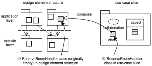
Instead, you want to keep the ReserveRoomHandler class within the Reserve Room use-case slice, as depicted in Figure 8-9. The left-hand side of Figure 8-9 depicts the design element structure. A structure is basically a containment hierarchy of elements of some kind—in this case, of the design element structure. It comprises layers and packages, and classes. The right-hand side depicts a use-case slice containing the specifics of the use-case realization.
We now discuss how to overlay the ReserveRoomHandler class in the Reserve Room use-case slice onto the design element structure (see Figure 8-9). First, you need to identify the class uniquely in the design element structure. This is achieved by giving a fully qualified name in the design element structure. Do note that at this moment, the ReserveRoomHandler in the design element structure is empty—you only have its name (see ![]() ). A composition mechanism (such as a compiler) would then compose the
). A composition mechanism (such as a compiler) would then compose the ReserveRoomHandler in the use-case slice (indicated by ![]() ) into the design element structure.
) into the design element structure.
Today, composing use-case-specific classes such as the one in Figure 8-9 is achievable in all compilers. Identifying a fully qualified name is achieved by specifying the namespace of the class in the design model. Namespaces are available in most conventional languages like C++, Java, and C#. In Java, this is achieved with the package keyword, as shown in Listing 8-1.
Example 8-1. Class Specific to Use-Case Realization: ReserveRoomHandler.java
1.  package app.customer ;
2.  public class ReserveRoomHandler {
3.    public void makeReservation() {
4.      // code
5.    }
6.  }
In line 1, we define the namespace for ReserveRoomHandler as residing in the customer package within the app (application) layer. After defining the namespace, we can start to define the ReserveRoomHandler class, as shown in line 2. Thereafter, we add the makeReservation() operation in lines 3, 4, and 5. Thus, we can keep classes specific to a use-case realization separate in a use-case slice.
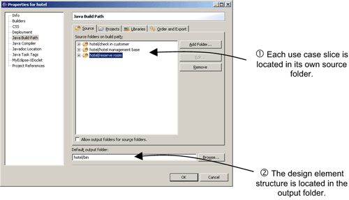
When you are working with source code, you are dealing with the implementation model. The implementation use-case structure represents your source files (i.e., *.java). The implementation element structure represents the binary files (i.e., *.class). Note that AspectJ can perform what is known as byte code—it can insert behavior into binaries even without source code.
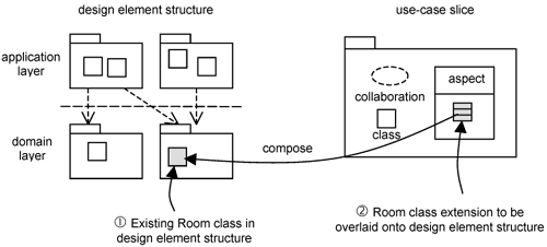
Let us now look at how to compose class extensions onto existing classes in the design element structure. This capability was not available in conventional languages until the advent of AOP. AOP provides you with intertype declarations to add features on top of existing classes. This is depicted in Figure 8-10 by the arrow labeled compose. The features to be overlaid onto an existing class are collated within a class extension.
In our example, the Room class is an existing class within the design element structure. It has been previously overlaid onto the design element structure, and now we want to overlay additional class extensions. Let’s assume that the Room class resides in the room package in a domain layer. Having identified the Room class, we can now overlay the Room class extension specific to the Reserve Room use-case slice onto the Room class in the design element structure.
This is achieved in AOP using aspects with intertype declarations. We call this aspect ReserveRoom, since it is used in the realization of the Reserve Room use case—we simply remove the space within string “Reserve Room.” Compilers today don’t like spaces. Listing 8-2 shows how you can add an operation to the existing Room class.
Example 8-2. Reserve Room Aspect in AspectJ: ReserveRoom.java
1.  package app.customer ;
2.  import domain.room.Room;
3.  public aspect ReserveRoom {
4.  public void Room.updateAvailability() {
5.  // code
6.  }
7.  }
Like the ReserveRoomHandler class, the ReserveRoom aspect resides in the application-layer customer package (see line 1 of Listing 8-2). This is the namespace for the aspect, not the class you are extending. Line 2 identifies the existing Room class that you want to extend. In lines 4, 5, and 6, we extend the Room class in the design element structure with a new operation, updateAvailability().
In this case, the aspect contains an intertype declaration for only one class. However, in general, you will compose multiple operations onto multiple classes. It will be natural for you to organize these intertype declarations that add features to the same class together, which is not required by AOP or AspectJ, in particular, but we find it a good practice to do so. That is why we have class extensions—they are modular extensions onto existing classes.
In addition, it is important to have a means to visualize and understand the overall effects aspects have on each individual class. Hence, it is extremely useful to explicitly model all advices and intertype declarations on each existing class. Moreover, this is how you work with collaborations today—you identify roles and then the attributes, operations, and so on, for that role. So, you see that class extensions are derived naturally when you identify roles in a collaboration. Thus, there is indeed methodological support for using class extensions.
Our proposed UML aspect contains class extensions, as depicted in Figure 8-11. This figure shows the ReserveRoom aspect containing a class extension called Room. The class extension is named this way so that you know which class its features must be composed into. In this case, the class extension has an updateAvailability() operation. During compilation, this will be composed into the existing Room class.
Recall that a use-case slice also has a collaboration describing the realization of the use case. The collaboration only describes a view of the model’s internal structure (comprising classes, subsystems, components, etc.) to show which of these elements are needed to realize the use case. The collaboration is not part of the internal structure itself. Consequently, you do not need an implementation construct for a collaboration.
As mentioned, a use-case slice contains elements that are specific to a particular use case. What about those elements that are required by more than one peer use-case slice? For example, the retrieve() operation in the Room class is used in both Reserve Room and Check In Customer use-case slices. You cannot put shared elements in any of the peer use-case slices because that will mean a dependency from one peer use-case slice to another, which violates the very idea of peers—there should not be relationships between them.
Recall that in use-case modeling, you can factor out common behaviors with use-case include and generalization. You can apply a similar technique with use-case slices and define corresponding semantics for include and generalization relationships between use-case slices. Another way is to put these common classes and features into what we call a non-use-case-specific slice.
An included use-case slice is used to factor out commonalities across use-case realizations. Figure 8-12 shows the Reserve Room use case, including the Check Room Details use case. The Check Room Details use case is a utility use case that contains a set of flows that are useful for making general queries on rooms, such as checking room availability, checking room rates, checking who is staying in the room at the moment, and checking the outstanding charges for the room. Such flows are included not only by the Reserve Room use case but also by many other use cases in the Hotel Management System, such as Check In Customer and Check Out Customer use cases.
The Check Room Details use case provides the ability to retrieve rooms. Let’s assume that this functionality is used often and there is some caching mechanism to make retrieval faster. The realization of the Check Room Details use case comprises two classes: CheckRoomHandler, which plays the role of a controller, and the Room class, which plays the role of a resource.
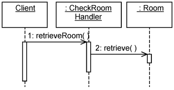
Figure 8-13 shows the interaction between instances of the two classes. Let’s assume that the CheckRoomHandler maintains a local cache containing data values of room details to minimize retrievals from the data-store. When some client invokes the retrieveRoom() operation on a CheckRoomHandler instance, the latter first tries to get data values from its cache. If the data values are not available, CheckRoomHandler instance invokes retrieve() on a Room instance to retrieve them from the datastore. If local data values are available, it is returned to the client.
Let us see how the include relationship between use cases gets propagated to their use-case realizations and, hence, how the including use-case slice can make use of the included use-case slice. This is modeled as a dependency between use-case slices. Figure 8-14 shows the Reserve Room (i.e., including) use-case slice, including the Check Room Details (i.e., included) use-case slice. We model the include relationship between use-case slices as a dependency stereotyped as «include».
Recall that a use-case slice comprises collaborations, classes, and features specific to a use case in a model. Thus, semantics of the include relationship between use cases gets translated to relationships between these elements.
A collaboration identifies the features required by classes to play the roles in the collaboration. It provides the means to view what is needed by a use-case realization through interaction diagrams. The interaction diagrams in the including use-case slice can reference the interaction diagrams in the included use-case slice. This translates to a dependency from the including collaboration to the included collaboration.
Classes in the including use-case slice can make use of classes in the included use-case slice. For example, the ReserveRoomHandler class can have an association or a dependency to the CheckRoomHandler class. This allows a ReserveRoomHandler instance to make a call such as retrieveRoom() on a CheckRoomHandler instance.
Features defined in the included use-case slice are made available to the including use-case slice. This is exemplified by the retrieve() operation defined in the Check Room Details. The CheckRoomDetail aspect extends the Room class with this operation to be used by the ReserveRoomHandler instance defined in the Reserve Room use-case slice.
In this case, there are no dependencies between the aspects in the two use-case slices. They do not make use of each other. Only classes make use of each other, so dependencies between classes suffice.
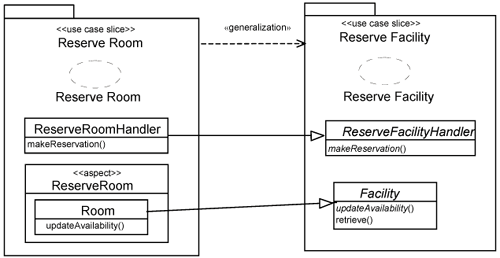
Recall that a parent use case has two purposes. First, it defines common behaviors that can be inherited by their children. Second, it acts like a template for their children. Figure 8-15 shows the Reserve Room use case inheriting from a Reserve Facility use case. The Reserve Facility use case is an abstract use case that describes in general terms the sequence of actions leading to the reservation of a facility. The Reserve Room use case specializes the Reserve Facility use case for making room reservations.
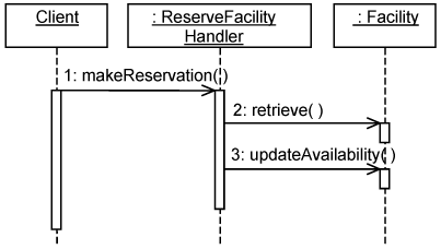
The realization of the parent use case is depicted through an interaction diagram in Figure 8-16. It shows the interaction between instances of the two classes. When some client invokes the makeReservation() operation on a ReserveFacilityHandler instance, the latter invokes retrieve() on a Facility and thereafter updates its availability.
Let us see how the generalization relationship between use cases is propagated to their use-case realizations and, hence, how the child use-case slice can utilize the parent use-case slice. Figure 8-17 shows the contents of the two use-case slices. We call the Reserve Room use-case slice the child use-case slice and the Reserve Facility use-case slice the parent use-case slice. For the purpose of discussion, let’s assume that both operations, makeReservation() and updateAvailability(), are abstract and that the retrieve() operation is concrete.
The collaborations in both use-case slices occur at different levels of abstraction. The Reserve Facility collaboration describes generic behaviors, and the Reserve Room use-case slice describes more specific behaviors. In general, they are separate (they describe things at different levels of abstraction), so there are no dependencies between them. But a child collaboration can make use of the parent collaboration, in which case there will be a dependency between collaborations.
A class such as the ReserveRoomHandler can have a generalization relationship to the ReserveFacilityHandler parent class and inherits the features of the parent class. Through the aspect, you can add a generalization relationship from the Room class to the Facility class through the aspect in the child use-case slice. These generalizations are depicted in Figure 8-11. Once the generalizations are added, a child can make use of its parent’s features.
If the features in the parent are abstract, the child has to make them concrete. In the example above, the makeReservation() operation in the ReserveFacilityHandler class is abstract. The ReserveRoomHandler class has to provide a concrete definition. The same goes for the updateAvailability() operation in the Facility class. If the features in the parent are concrete, the child can redefine them.
Let us consider what happens if the retrieve() operation in the Reserve Facility use-case slice is also abstract. Since, the Reserve Room use-case slice does not define it, it is incomplete. In this case, the Reserve Room use-case slice must include another use-case slice, such as the Check Room Details, or have a dependency to the non-use-case-specific slice to import the definition.
There can be generalization between aspects, but we discuss them in the next chapter.
Some classes are part of the problem domain, and they are used in many use-case realizations. The realization of the Reserve Room use case and the Check In Customer use case need the same Room class. In fact, this Room class us needed by many other use-case realizations, even included use-case slices like the Check Room Details discussed above.
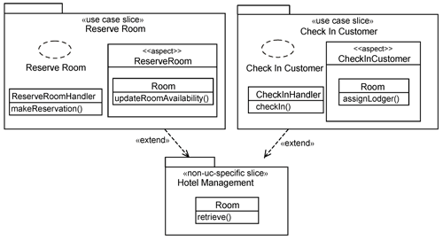
The Room class is part of the domain and is fundamental to the Hotel Management System. Without rooms, there wouldn’t be a hotel, let alone a Hotel Management System. Hence, the Room class is not use-case-specific and should not be defined in a use-case slice. Instead, it is part of what we call a non-use-case-specific slice. It is stereotyped as «non-uc specific slice». Other use-case slices will extend it, as depicted in Figure 8-18.
A non-use-case-specific slice is different from a use-case slice in that it contains no aspects. This is because it defines a base and does not need to add to any existing classes. Non-use-case-specific slices usually represent a domain of some kind. It can be a business domain, such as Hotel Management (see Figure 8-18), or it can be used to represent some technical or infrastructural domain, such as user interfaces or communications. These also normally need a set of common classes, which individual use-case slices will add on to. For example, different use-case slices might need to add their respective menu options to a common menu bar. We present many examples of non-use-case-specific slices in Part IV of the book when we discuss how to establish an architecture based on use cases and aspects.
In this chapter, we demonstrated how you can keep the realizations of peer use cases separate. This is achieved through a new modularity unit, which we call a use-case slice. A use-case slice contains the collaborations, classes, and features specific to a use-case realization. Table 8-1 summarizes the correspondence between elements of a use-case slice during design (with UML) and during implementation (with AOP).
Table 8.1. Mapping UML Constructs in to AOP Constructs
UML Constucts | AOP Constructs |
|---|---|
Use-case slice | Package |
Collaboration | None |
Aspect | Aspect |
Class extension | Grouping of intertype declarations for each class |
We have to emphasize that use-case slices are not the typical packages you find in a design model. The design model contains a hierarchical element structure in terms of layers, packages, and so on. Even though use-case slices are part of the design model, they are orthogonal to this element structure. Use-case slices are overlays on top of this element structure. Each time you add a use-case slice on top of this element structure, you superimpose the contents of the use-case slice into it. If you remove a use-case slice, all contents in the use-case slice (class and features) are removed from this element structure as well.
In this chapter, we also showed how the include and generalization relationships between use cases in the use-case model are translated to corresponding relationships between use-case slices in the design model. In the next chapter, we show how the extend relationship in the use-case model is propagated into the design model. In this way, we have preserved all use-case relationships existing in the use-case model in the design model.

