In Appendix A, we gave an overview of the notation used to model aspects. In this appendix, we give a quick guide to the UML representation of other elements used in this book. The purpose is to highlight how these elements are used. For a more detailed discussion on the notation, please refer to the UML specification itself.
A package is an element that is used to group other elements.
You normally assign work to developers in terms of packages rather than individual classes. We use different kinds of packages in the book.
Layers are used as the first-level partitioning in a model. Layers group software elements that are on the same level of abstraction. See Chapter 11, Section 11.4.1.
A tier package is a package representing a subset of a logical tier in the design package. See Chapter 15, Section 15.1.2.
A model contains a (hierarchical) set of elements that together describe the system being modeled. A model may contain more than one structure. In this book, the discussion is largely on the use-case model, the analysis model, and the design model. See Chapter 10.
An actor models a type of role played by an entity that interacts with the system. Actors may represent roles played by human users, external hardware, or other external systems.
A use case is the sequence of actions performed by a system, which yields an observable result that is typically of value for one or more actors or other stakeholders of the system. A use case models the behavior of the system, including possible variants when the actor uses the system.
An actor is denoted using a stick figure; a use case is denoted using an ellipse.

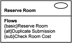
The rectangular classifier notation provides another means to represent a use case, but it now shows the details of the use case. See Chapter 5.

Using the rectangular classifier notation for use cases, you can highlight the different flow of events within a use case: basic flows, alternate flows, and subflows.
In this book, we apply use cases to model both application and infrastructure. Broadly speaking, application use cases capture concerns arising from functional requirements, whereas infrastructure use cases capture concerns arising from nonfunctional requirements. See Chapter 7.
A class models a set of objects that share the same specifications of features (attributes, operations, and relationships), constraints, and semantics. An instance is one such object.
In essence, a class represents a type, and an instance is a concrete manifestation of the type.
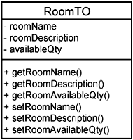
A class is represented as a rectangle with three compartments. The top compartment shows the name, the second compartment shows its attributes, and the third shows its operations. In this book, we frequently hide the second compartment and thus show only class names and operations.

An instance is also denoted as a rectangle, and the name of the instance is underlined. We use instances in interaction and communication diagrams.

The name of an instance is of the form X:Y, where X is the name of the instance and Y is the name of the class. In this book, we frequently leave the instance anonymous—that is, X is not defined.
There are many different kinds of classes used in this book. In the analysis model, are three stereotyped classes: boundary, control, and entity. See Chapter 10, Section 10.3.1.

In the design model, the analysis classes are mapped to their design counterparts. To distinguish them, the boundary, control, and entity classes in design are depicted with rectangles; those in analysis are circles. See Chapter 10, Section 10.4.1.

The design boundary, control, and entity classes are also known as POJOs (Plain Old Java Objects) in this book. They represent minimum design classes that make little use of platform specifics.
There are a number of class stereotypes in design, such as transfer objects, data access objects, and business delegates. These are discussed extensively in Chapter 15.
Between a class and an interface is a realization relationship. This relationship indicates that a class conforms to the behaviors specified in the interface.
Classes in different models can be related with a trace relationship, which indicates that one element in a model is mapped from one element in another model.
A component is a modular part of a system that encapsulates its contents and the manifestation of which is replaceable within its environment. A component defines its behavior in terms of provided and required interfaces. As such, a component serves as a type, and its conformance is defined by these provided and required interfaces.
An interface is a named set of operations that characterize the behavior of an element (e.g., class, component).
A component is represented using a rectangle with a component stereotype. Provided interfaces are denoted as balls, and required interfaces are denoted as sockets.

Components appear only during design. They do not appear in analysis. In other words, components are design elements.
In this book, we often discuss components in the context of incorporating extensibility into the system. Use-case slices are used to extend existing components with required interfaces through which other components can be plugged into the system. See Chapter 13, Section 13.3.
A process is a unit of concurrency and execution in an operating system.
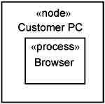
A node represents a runtime computational resource, which generally has at least memory and often processing capability.
A node is represented in this book by a rectangular stereotyped «node». A process is represented as a rectangular stereotyped «process».


