
Chapter 1
Quick Start for New AutoLISP Programmers
The AutoLISP® language and programming in general are two subjects that I have enjoyed for over 15 years now, but the same subjects make some people cringe and want to run in the opposite direction. I am not going to claim AutoLISP is easy to learn, but it can be learned by anyone, whether or not they have a programming background. When I first set out to learn AutoLISP, I didn't have any programming experience, but I wanted the benefits that AutoLISP could offer.
I understand if you have some hesitation at the thought of learning AutoLISP, but you don't need to feel that way—I will help you. This chapter will ease you into some core programming concepts and the AutoLISP programming language by exposing you to a variety of functions that are available.
To complete the exercises in this chapter and be able to create and edit LSP files, you must have the following:
- For Windows users: Autodesk® AutoCAD® 2006 or later and the Notepad program
- For Mac OS users: Autodesk® AutoCAD® 2011 or later and the TextEdit program
Working with AutoLISP Expressions
AutoLISP is a natural extension of AutoCAD, as it can be used seamlessly from the AutoCAD Command prompt. You can enter AutoLISP when no commands are active or when AutoCAD prompts you for a value. The programming statements used in AutoLISP are known as expressions. You can type expressions at the Command prompt as long as they start with an opening parenthesis [(] or an exclamation point (!). Follow those symbols with the functions you wish to execute and the arguments that provide data or further instruction.
Each AutoLISP expression that starts with an opening parenthesis must also end with a closing parenthesis. AutoLISP expressions must contain the same number of opening and closing parentheses—this is sometimes referred to as balancing parentheses. You can enter the opening and closing parentheses on separate lines, though.
Use these steps to gain a basic understanding of entering AutoLISP expressions at the AutoCAD Command prompt:
- Launch AutoCAD, if it is not already running.
- At the AutoCAD Command prompt, type
(and press Enter.AutoCAD responds with the prompt
(_>, which is the program's way of letting you know that AutoLISP has taken control. - Press Esc to return to the standard AutoCAD Command prompt.
- At the AutoCAD Command prompt, type
(+ 3 2)and press Enter.The AutoLISP expression is evaluated and returns a value of 5, which is the result of adding 3 and 2 together. The
+(plus sign) is the function of the AutoLISP expression;3and2are the arguments (in this case, data) that are passed to the function. The AutoLISP function you want to use must be the first item after the opening parenthesis. - Type
(* 3.5 2)and press Enter.The value 7.0 is returned as a result of multiplying 3.5 by 2.
- Type
(setq rad (/ 0.375 2))and press Enter.The value 0.1875 is returned as a result of dividing 0.375 by 2, but the same value is also assigned to the user-defined variable named rad with the
setqfunction. AutoLISP expressions can be nested one inside of another, and they are evaluated from the innermost to the outermost expression. In this example, the expression(/ 0.375 2)is evaluated first and returns 0.1875. The next expression,(setq rad 0.1875), is evaluated and it also returns 0.1875. - Type
circleand press Enter.The AutoCAD
circlecommand is started. - At the
Specify center point for circle or [3P/2P/Ttr (tan tan radius)]:prompt, type(list 0 5)and press Enter.The
(list 0 5)expression returns a value of (0 5), which is a list of two values that presents the 2D coordinate of 0,5. The center of the circle is started at 0,5,0. - At the
Specify radius of circle or [Diameter]:prompt, type!radand press Enter.AutoLISP evaluates the rad user-defined variable and returns its value to be used for the circle's radius. The radius of the circle should be set to 0.1875.
- In the drawing area, select the new circle.
- On Windows, right-click in the drawing area and choose Properties. If you are using AutoCAD on Mac OS, secondary-click (two-finger tap or right-click) in the drawing area and choose Properties.
- In the Properties palette (Windows) or Properties Inspector (Mac OS)—see Figure 1.1—you should notice that the Center properties are set to 0,5,0 (X=0.0, Y=5.0, and Z=0.0) and the Radius property is set to 0.1875.
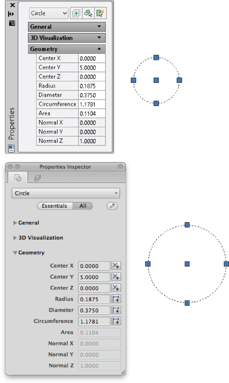
Figure 1.1 Result of using AutoLISP expressions with the
circlecommand
 In this exercise, you did the following:
- Entered AutoLISP expressions at the AutoCAD Command prompt and stored values in a user-defined variable (see Chapter 2, “Understanding AutoLISP,” for more information)
- Used functions to perform basic math calculations (see Chapter 3, “Calculating and Working with Values,” for more information)
- Created a list that represented a 2D coordinate (see Chapter 4, “Working with Lists,” for more information)
Working with Commands and Input
In addition to calculating values with AutoLISP and passing those values to a command, you can execute a command as part of an AutoLISP expression using the command function. Input can also be requested and passed to a command or saved to a user-defined variable.
The following steps demonstrate how to create a layer named Circles with an AutoCAD Color Index (ACI) of 30 using the -layer command. You'll then draw a circle on the new layer with a user-specified center point and radius.
- At the AutoCAD Command prompt, type
(command "-layer" "m" "Circles" "c" "30" " " " ")and press Enter.The
-layercommand is started. The Make (m) option of the command is used to create the layer named Circles. After the Circles layer is created (or if it already exists), the Make option makes that layer current. The Color (c) option is then used to set the color of the Circles layer to ACI 30. - Type
(command "circle" PAUSE PAUSE)and press Enter.The
circlecommand is started and theSpecify center point for circle or [3P/2P/Ttr (tan tan radius)]:prompt is displayed. AutoCAD displays this prompt because the predefinedPAUSEvariable is used as the response to the command's prompt for a value. - At the
Specify center point for circle or [3P/2P/Ttr (tan tan radius)]:prompt, pick a point in the drawing area. - At the
Specify radius of circle or [Diameter]:prompt, type0.1875and press Enter.This command draws a circle with a radius of 0.1875 and places it on the Circles layer.
- At the Command prompt, type the following and press Enter:
(setq cenPt (getpoint " Specify a center point: ")).The
getpointfunction requests a point in the drawing area and can display an optional custom prompt to the user. - At the
Specify a center point:prompt, specify a point in the drawing area.The point you specified is assigned to the cenPt user-defined variable.
- At the Command prompt, type
(setq rad (getreal "
Enter radius: "))
and press Enter.The
getrealfunction requests a numeric value. - At the
Enter radius:prompt, type0.25and press Enter.The value of 0.25 is assigned to the rad user-defined variable.
- Type
(command "circle" cenPt rad)and press Enter.AutoCAD starts the
circlecommand and draws a new circle based on the values assigned to the cenPt (center point) and rad (radius) user-defined variables.
Now that you've entered some short expressions, let's look at creating long expressions—expressions that can span multiple lines. Using the following steps, you will also see how to give feedback to the user based on values they provided in the form of the center point and radius of the circle.
- Type
(prompt (strcat "
New circle: "
and press Enter.The
promptfunction allows you to return messages and values to the user, and thestrcatfunction is used to combine multiple string values into a single string. This AutoLISP expression starts on this line and spans to the next line because no closing parentheses were provided. When an AutoLISP expression is not completed, the AutoCAD prompt displays the number of closing parentheses required to complete the current AutoLISP expression. For example,((_>indicates you need to enter two closing parentheses to get back to the standard AutoCAD Command prompt. - Type
"
Center Point " (vl-princ-to-string cenpt)
and press Enter.The
vl-princ-to-stringfunction allows you to display the current value assigned to a user-defined variable as a string. Here thevl-princ-to-stringfunction converts the list that represents the center point of the circle to a string. - Type
"
Radius: " (rtos rad)
and press Enter.The
rtosfunction converts a numeric value of the radius to a string. - Type
)and press Enter.This closing parenthesis ends the
strcatexpression that we started in Step 1. - Type
)and press Enter.This closing parenthesis ends the
promptexpression that we started in Step 1. The message returned by thepromptfunction should look similar to the following:New circle: Center Point: (21.9627 6.18679 0.0) Radius: 0.2500nil
In these exercises, you did the following:
- Used standard AutoCAD commands to create a layer and draw a circle (see Chapter 2 for more information)
- Requested input from the user and displayed information back to the user (see Chapter 5, “Requesting Input and Using Conditional and Looping Expressions,” for more information)
- Converted values from one type of data to another (see Chapters 3 and 4 for more information)
Conditionalizing and Repeating Expressions
Complex programs often contain branches (different sets of expressions that are used to handle different conditions or choices by the user), and they might loop (execute a set of expressions multiple times). Conditional expressions allow your programs to use a programming concept known as branching. Branching gives your programs the ability to execute different expressions based on the input a user provides or the current value of a system variable. When modifying large sets of data or even prompting a user for input, you can use looping expressions to repeat a set of expressions while a condition is met.
This exercise demonstrates some of the conditional and looping expressions that are available in AutoLISP:
- At the AutoCAD Command prompt, type
(if (= (tblsearch "layer" "Circles") nil)and press Enter.The
iffunction is used to test whether a condition is true or false. If the=comparison operator returnsT, then the first expression is evaluated; otherwise, the second expression is. Thetblsearchfunction is used to check to see if a layer, linetype, or some othernongraphicalobject already exists in a drawing. - Type
(command "-layer" "m" "Circles" "c" "30" " " " ")and press Enter.This command creates the new Circles layer if it doesn't exist in the drawing.
- Type
(prompt "
Layer already exists.")
and press Enter. - Type
)and press Enter.The closing parenthesis ends the
iffunction. Either the Circles layer is created or the messageLayer already exists.is displayed. Entering the four expressions again results in the displaying of the message. - Type
(setq cnt 0)and press Enter.The
setqfunction defines a user-defined variable namedcntand assigns it the value of 0. - Type
(command "circle" (list 0 0) 1)and press Enter.This command draws a circle at 0,0 with a radius of 1 on the “Circles” layer.
- Type
(repeat 7and press Enter.The
repeatfunction is used to repeat a set of AutoLISP expressions a specific number of times. - Type
(setq cnt (1+ cnt))and press Enter.The
1+function increments the current value ofcntby 1 each time the expression is evaluated. - Type
(command "circle" (list 0 0) (* (getvar "circlerad") 1.5))and press Enter.Once you enter the expressions within the
repeatloop and add the final closing parenthesis to complete the expression, AutoCAD draws a new circle at 0,0 with a radius that is 1.5 times larger than the previous circle that was drawn. The previous radius used to create a circle with thecirclecommand is stored in thecircleradsystem variable. Thegetvarfunction returns the current value of a system variable. - Type
(command "change" (entlast) " " "p" "c" cnt " ")and press Enter.The
changecommand modifies the color of the recently drawn circle, or more specifically the last object in the drawing. Theentlastfunction returns the last object added to the drawing. - Type
)and press Enter.The closing parenthesis ends the
repeatfunction. Seven concentric circles, as shown in Figure 1.2, are drawn around the circle that was drawn outside of the repeat loop. Each circle drawn inside the repeat loop is assigned a different color, and the radius of each circle is 1.5 times larger than the next inner circle.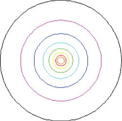
Figure 1.2 Drawing concentric circles with AutoLISP
In the previous exercise, you did the following:
- Used comparison operators and conditional functions to evaluate different expressions based on the results of a test condition (see Chapter 5 for more information)
- Used math-based functions to calculate the radius of a circle and to increment a counter used in a looping expression (see Chapter 3 for more information)
- Checked to see if a layer existed in the drawing (see Chapter 7, “Creating and Modifying Nongraphical Objects,” for more information)
- Repeated a set of AutoLISP expressions until a condition was met (see Chapter 5 for more information)
Grouping Expressions
Entering individual expressions can be helpful when you are first learning AutoLISP or when you are developing a new program, but it isn't ideal for you to do each time you want to execute a set of AutoLISP expressions. The AutoLISP programming language allows you to define a custom function that can be executed at the Command prompt or from a command macro assigned to a user-interface element, such as a ribbon or toolbar button.
The following steps demonstrate how to define a custom function named RectangularRevCloud that can be entered at the AutoCAD Command prompt:
- At the AutoCAD Command prompt, type the following and press Enter:
(defun c:RectangularRevCloud ( / arclength)The
defunfunction is used to define a function. The function defined is namedRectangularRevCloudand contains one local variable namedarclength. Local variables are accessible only to the function in which they are defined. - Type the following and press Enter:
(if (= (tblsearch "layer" "RevCloud") nil)
  (command "-layer" "m" "RevCloud" "c" "1" "" "")
)
The expressions test to see if a layer named RevCloud exists, and if it doesn't, the layer is created and assigned the color red (1).
- Type the following and press Enter:
(command "rectang" PAUSE PAUSE)The
rectangcommand is used to draw a rectangle based on the two points the user provides. - Type the following and press Enter:
(if (> (setq arclength (abs (getvar "dimscale"))) 1)
  (setq arclength (* arclength 2))
  (setq arclength 1.0)
)
The
>operator and theiffunction determine whether the value of thedimscalesystem variable is greater than 1. If so, the value is used to set the arc length for the revision cloud that will be created from the rectangle. If the value ofdimscaleis less than 1, then the value of 1 is used. The calculated maximum arc length value is assigned to the user-defined variable named arclength. - Type the following and press Enter:
  (command "revcloud" "a" (/ arclength 2) arclength "o" (entlast) "")
 (princ)
)
The
revcloudcommand converts the rectangle that was drawn with therectangcommand to a revision cloud. Theprincfunction keeps the last expression in the function definition from returning a value and allowing the function to “exit quietly.” The final closing parenthesis closes thedefunfunction. - Type the following and press Enter:
(defun c:RRC ( / )(c:RectangularRevCloud)) - The
RRCcustom function acts as an alias to theRectangulatRevCloudfunction and makes it easier to start the function from the Command prompt. - Type
RectangularRevCloudand press Enter. - At the
Specify first corner point or [Chamfer/Elevation/Fillet/Thickness/Width]:prompt, specify the first corner of the rectangle. - At the
Specify other corner point or [Area/Dimensions/Rotation]:prompt, specify the opposite corner of the rectangle.The rectangle is drawn on the layer “RevCloud” and converted to a revision cloud using the Object (
o) option of therevcloudcommand; see Figure 1.3.
Figure 1.3 Converting a rectangle to a revision cloud
- Type
RRCand press Enter. Specify the two corners of the rectangle.RRCis simply a shortcut to the newRectangularRevCloudfunction.
In the previous exercise, you did the following:
- Grouped a set of AutoLISP expressions into a custom function to make it easier to execute the expressions (see Chapter 2 for more information)
- Accessed the value of a system variable (see Chapter 2 for more information)
Storing and Loading AutoLISP Expressions
AutoLISP expressions entered at the AutoCAD Command prompt are accessible from that drawing and only while that drawing remains open. You can store AutoLISP expressions in an LSP file that, once saved, can then be loaded into and executed from any drawing file that is opened in AutoCAD. The following exercise explains how to create and load an LSP file named acp_qs.lsp.
If you are on Windows:
- Do one of the following:
- On Windows XP or Windows 7, click Start
 [All] Programs Accessories Notepad.
 - On Windows 8, on the Start Screen, type note and then select Notepad from the Search bar.
- On Windows XP or Windows 7, click Start
- In Notepad, click File Save As.
- In the Save As dialog box, browse to the
Documents(orMy Documents) folder or theMyCustomFilesfolder that you created for the exercises and examples in this book. - In the File Name text box, type
acp_qs.lsp. - Click the Save As Type drop-down list and select All Files (*.*).
- Click the Encoding drop-down list and select ANSI. Click Save.
- In the text editor area, type the following expressions. Replace the square brackets and the text inside them with the current date and your name.
; Created [Today's date] by [Your name] – Quick Start Examples ; Zoom shortcuts (defun c:ZE ( / ) (command "._zoom" "e")) (defun c:ZW ( / ) (command "._zoom" "w")) ; Repeat Purge command 3 times to remove nested objects ; and remove zero lines and empty objects (defun c:P3 ( / ) (repeat 3 (command "._-purge" "_all" "*" "_n") ) (command "._-purge" "_z") (command "._-purge" "_e") ) ; List which objects are in a selection set (defun c:ListObjects ( / selectedObjects count ent) (prompt " Select objects to list: ") (setq selectedObjects (ssget) count 0 ) (if (/= selectedObjects nil) (progn (while (> (sslength selectedObjects) count) (setq ent (ssname selectedObjects count)) (terpri) (prompt (cdr (assoc 0 (entget ent)))) (setq count (1+ count)) ) (prompt (strcat " Total objects processed: " (itoa count))) ) ) (princ) ) - Click File Save.
If you are running AutoCAD on Mac OS, use the following steps to create an LSP file named acp_qs.lsp:
- In the Mac OS Finder, click Go Applications. In the Finder window, double-click TextEdit.
- In TextEdit, click TextEdit Preferences. In the Preferences dialog box, on the New Document tab click Plain Text and deselect Smart Quotes. Close the dialog box.
- Click File New to create a plain ASCII text file.
- Click File Save and type
acp_qs.lspin the Save As text box. On the sidebar at the left, clickDocumentsor theMyCustomFilesfolder that you created for the exercises and examples in this book. Click Save. - If prompted to use the
.lspextension, click Use .Lsp. - In the text editor area, type the following expressions. Replace the square brackets and the text inside them with the current date and your name.
; Created [Today's date] by [Your name] – Quick Start Examples ; Zoom shortcuts (defun c:ZE ( / ) (command "._zoom" "e")) (defun c:ZW ( / ) (command "._zoom" "w")) ; Repeat Purge command 3 times to remove nested objects ; and remove zero lines and empty objects (defun c:P3 ( / ) (repeat 3 (command "._-purge" "_all" "*" "_n") ) (command "._-purge" "_z") (command "._-purge" "_e") ) ; List which objects are in a selection set (defun c:ListObjects ( / selectedObjects count ent) (prompt " Select objects to list: ") (setq selectedObjects (ssget) count 0 ) (if (/= selectedObjects nil) (progn (while (> (sslength selectedObjects) count) (setq ent (ssname selectedObjects count)) (terpri) (prompt (cdr (assoc 0 (entget ent)))) (setq count (1+ count)) ) (prompt (strcat " Total objects processed: " (itoa count))) ) ) (princ) ) - Click File menu Save.
The next exercise explains how to load the acp_qs.lsp file you created in the previous steps:
- Launch AutoCAD, or switch to AutoCAD if it is already running, and do one of the following:
- On the ribbon, click Manage tab Customization panel Load Application (Windows).
- On the menu bar, click Tools Load Application (Mac OS).
- At the Command prompt, type
apploadand press Enter (Windows and Mac OS).
- On the ribbon, click Manage tab
- When the Load/Unload Applications dialog box (see Figure 1.4) opens, browse to the
Documents(orMy Documents) folder or theMyCustomFilesfolder, and select theacp_qs.lspfile. Click Load. - If the File Loading - Security Concerns message box is displayed, click Load.
- Click Close to return to the drawing area.
- Draw some objects and create about three layers in your drawing.
- At the Command prompt, type
zeand press Enter.The drawing is zoomed to its extents.
- Type
zwand press Enter. Specify the two corners of the window.The drawing is zoomed in based on the defined window.
- Type
listobjectsand press Enter. Select the objects to list and press Enter. Press F2 on Windows or Fn-F2 on Mac OS to expand the command-line window (or open the AutoCAD Text Window on Windows).The object names of the selected objects are output to the command-line window. The following is sample output:
LINE LWPOLYLINE CIRCLE CIRCLE Total objects processed: 4 - Type
p3and press Enter. The layers that you created in step 5, which are not being used in the drawing, should now have been removed.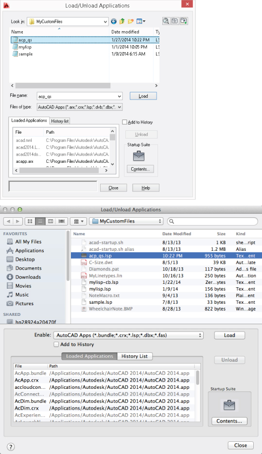
Figure 1.4 Loading the
acp_qs.lspfile
In the previous exercise, you did the following:
- Created an LSP file to store AutoLISP expressions (see Chapter 10, “Authoring, Managing, and Loading AutoLISP Programs,” for more information)
- Loaded an LSP file into AutoCAD (see Chapter 10 for more information)