
Chapter 6
Creating and Modifying Graphical Objects
The AutoLISP® programming language is great for creating and modifying objects. There are two types of objects that you can create or modify: graphical and nongraphical. Graphical objects are those that you can see and interact with in the drawing area, whether in model or paper space. Nongraphical objects are those that you don't create in the drawing area but that can affect the appearance of graphical objects. I discuss working with nongraphical objects in Chapter 7, “Creating and Modifying Nongraphical Objects.”
The command function is the most common method that AutoLISP programmers use to create and modify objects, but it isn't the most efficient when you are trying to modify individual properties of an object. Even creating lots of objects in the Autodesk® AutoCAD® program can be slower with the command function. Along with the command function, objects can be created and modified directly by setting property values as part of an entity data list. Extended data (XData) can also be attached to an object as a way to differentiate one object from another or, in some cases, to affect the way an object might look in the drawing area.
Working with Entity Names and Dotted Pairs
Creating and modifying objects with AutoLISP requires the understanding of two concepts: entity names and entity data. Entity names, also known as enames, are numeric values that are assigned to graphical and nongraphical objects stored in a drawing. An ename is expressed as the ENAME data type in AutoLISP. When you want to access an object, you use an ename. After an ename has been obtained, you can then access the object's properties through its entity data list. An entity data list is a list that contains information about an object. In addition to modifying an object using an entity data list, you can create objects with entity data lists. I discuss how to create an object with an entity data list in the “Adding Objects to a Drawing” section, and how to get an ename for an object and the entity data list in the “Modifying Objects” section.
Each entity data list is made up of many smaller lists that describe the properties of an object. The smaller lists are value pairings commonly known as dotted pairs. They are called dotted pairs because a dot usually separates the key element from the value of the list. The key element is commonly a DXF group code (which is of the integer data type) and used to let AutoCAD know the type of data for the value in the dotted pair. Some DXF group codes have common uses, whereas others have a more general meaning. I discuss some DXF group codes during this chapter, but you will need to refer to the AutoCAD Help system for a listing of all supported DXF group codes by object.
The value of a dotted pair can be made up of more than one item. When a value contains more than one item, no dot is provided, as is the case with coordinate values. Here is an example of an entity data list for a circle:
((-1 . <Entity name: 7ff79b005dc0>) (0 . "CIRCLE")
 (330 . <Entity name: 7ff79b0039f0>) (5 . "1D4") (100 . "AcDbEntity")
 (67 . 0) (410 . "Model") (8 . "0") (100 . "AcDbCircle")
 (10 0.0 0.0 0.0) (40 . 0.875) (210 0.0 0.0 1.0))
The DXF group codes 10 and 40 are used to describe the circle. The DXF group code 10 represents the center point of the circle (10 0.0 0.0 0.0), whereas the DXF group code 40 represents the radius of the circle, which is set to a value of 0.875. Even though you can use the circle command to create a circle based on a diameter value, AutoCAD stores only the circle's radius as part of the drawing.
DXF group codes don't always have the same meaning. For example, the DXF group code 10 is used by both lines and circles, but for line objects the code represents the line's starting point, as shown in the following entity data list:
((-1 . <Entity name: 7ff79b005e00>) (0 . "LINE")
 (330 . <Entity name: 7ff79b0039f0>) (5 . "1D8") (100 . "AcDbEntity")
 (67 . 0) (410 . "Model") (8 . "0") (100 . "AcDbLine")
 (10 0.0 5.0 0.0) (11 5.0 5.0 0.0) (210 0.0 0.0 1.0))
Table 6.1 lists some of the most common DXF group codes that are used by objects in a drawing. For additional information on DXF group codes, search on “DXF entities section” in the AutoCAD Help system.
Table 6.1 Common DXF group codes
| DXF group c0de | Description |
| 0 | Specifies the object's type |
| 6 | Specifies the linetype that an object is assigned; not used if the linetype is assigned by layer |
| 8 | Specifies the layer on which an object is placed |
| 10 | Specifies the start, center, elevation, or insertion point for many different objects |
| 11 | Specifies the endpoint or direction vector for many different objects |
| 40 | Specifies the radius for circles, height for text, and ratio between the major and minor axis of an ellipse |
| 62 | Specifies the color that an object is assigned; not used if the color is assigned by layer |
Creating a Dotted Pair
A dotted pair is a list that is created using the AutoLISP cons or quote (') function. When creating a dotted pair, you need to know two things: the key element and the value to be associated with the key element. Although the key element can be of any data type with the exception of a list, it is commonly either a string or integer. In entity data lists, the key element is an integer value that represents a DXF group code.
The following shows the syntax of the cons function:
(cons key atom)The arguments are as follows:
keyThekeyargument represents the index or unique identifier for the dotted pair.atomTheatomargument represents the value that you want to associate with the index or unique identifier specified by thekeyargument.
The following examples show how to create dotted pairs with the cons function, and the values that are returned:
; Dotted pair with a system variable name as the key and its value
(cons "cmdecho" 0)
("cmdecho" . 0)
; DXF group code 10 with a coordinate value of 0.5,5.5,0
(cons 10 (list 0.5 5.5 0.0))
(10 0.5 5.5 0.0)
; DXF group code 40 with a value of 0.875
(cons 40 0.875)
(40 . 0.875)
You can also use the quote function to create a dotted pair. The following examples show how to create dotted pairs with the quote function, and the values that are returned:
; Dotted pair with a system variable name as the key and its value
'("cmdecho" . 0)
("cmdecho" . 0)
; DXF group code 10 with a coordinate value of 0.5,5.5,0
'(10 0.5 5.5 0.0)
(10 0.5 5.5 0.0)
; DXF group code 40 with a value of 0.875
'(40 . 0.875)
(40 . 0.875)
Accessing the Elements of an Entity Data List and Dotted Pair
Accessing the elements of an entity data list and a dotted pair is like accessing the elements of a regular list. Although you can use many of the list-related functions that I discussed in Chapter 4, “Working with Lists,” the AutoLISP assoc function is one of the functions that is frequently used when working with an entity data list. The assoc function is used to return a dotted pair with a specific key element in an entity data list.
The following shows the syntax of the assoc function:
(assoc key edlist)The arguments are as follows:
keyThekeyargument represents the key (left) element of a dotted pair and is used as a way to locate a dotted pair within the list specified by theedlistargument. This argument can be a string or integer value.EdlistTheedlistargument represents the list in which you want to look for a dotted pair that contains thekeyargument as the key element. The first matching dotted pair is returned.
Here is an example that shows how to return the first dotted pair in the entity data list that has a key (left) element of 40:
; Returns the entity data list of the last object
; added to the drawing, which is a circle in this example
(setq ed (entget (entlast)))
((-1 . <Entity name: 7ff773005dc0>) (0 . "CIRCLE")
 (330 . <Entity name: 7ff7730039f0>) (5 . "1D4") (100 . "AcDbEntity")
 (67 . 0) (410 . "Model") (8 . "0") (100 . "AcDbCircle")
 (10 5.0 6.5 0.0) (40 . 2.0) (210 0.0 0.0 1.0))
; Returns the dotted pair with the key element of 40 in the entity data list
(assoc 40 ed)
(40 . 2.0)
I explain the entlast and entget functions in the “Selecting an Individual Object” and “Updating an Object's Properties with an Entity Data List” sections later in this chapter.
The AutoLISP car and cdr functions can also be helpful when working with dotted pairs. The car function returns the key element of a dotted pair and the cdr function returns the value.
; Returns the key element of the dotted pair
(car (assoc 40 ed))
40
; Returns the value of the dotted pair
(cdr (assoc 40 ed))
2.0
Adding Objects to a Drawing
Adding objects to a drawing can be done using standard AutoCAD commands with the command or entmake function. The entmake function accepts an entity data list that defines an object to be added to the drawing. All of the properties required to create an object must be contained in the entity data list; otherwise, the object won't be created. The properties required by the object are documented as part of the DXF Reference documentation in the AutoCAD Help system, but you might need to perform some trial and error to develop the proper entity data list that creates a new object.
For some objects it's easier to determine which properties are required; for example, a circle requires a center point and radius whereas a line requires a start and endpoint. The best way to figure out which properties are required when creating an object is to create a new object in a drawing of the type you want to create with the entmake function. Once the object is created, enter the following code at the AutoCAD Command prompt to see the entity data list associated with the object:
(entget (entlast))For example, if you drew a circle with a center point of 5,6.5,0 and a radius of 2.0, the entity data list that is returned might look like this:
((-1 . <Entity name: 7ff773005dc0>) (0 . "CIRCLE")
 (330 . <Entity name: 7ff7730039f0>) (5 . "1D4") (100 . "AcDbEntity")
 (67 . 0) (410 . "Model") (8 . "0") (100 . "AcDbCircle")
 (10 5.0 6.5 0.0) (40 . 2.0) (210 0.0 0.0 1.0))
In the previous example, the DXF group codes −1, 5, and 330 were automatically generated and assigned to the object. Those DXF group codes shouldn't be part of the entity data list when you create a new object with the entmake function. Table 6.2 describes the DXF group codes −1, 5, and 330.
Table 6.2 Automatically generated DXF group code values
| DXF group code | Description |
| −1 | Ename assigned to the object while the drawing is open in memory; the value changes each time the drawing is opened. |
| 5 | Unique handle that is assigned to the object; it's a string value. |
| 330 | Pointer to the owner of the object. |
After removing the DXF group codes that are automatically generated, the entity data list looks a bit less cluttered and easier to understand:
((0 . "CIRCLE") (100 . "AcDbEntity") (67 . 0) (410 . "Model") (8 . "0")
 (100 . "AcDbCircle") (10 5.0 6.5 0.0) (40 . 2.0) (210 0.0 0.0 1.0))
The DXF group codes 67, 410, 8, and 210 are optional; if they aren't provided as part of the entity data list, AutoCAD uses the current settings and context of the drawing to populate the values of the properties they represent. Table 6.3 describes the DXF group codes 67, 410, 8, and 210.
Table 6.3 Optional DXF group code values
| DXF group code | Description |
| 67 | Indicates that the object is in model space (0) or paper space (1) |
| 410 | Named layout tab that the object exists on |
| 8 | Layer in which the object is placed |
| 210 | Extrusion direction of the object |
After removing the DXF group codes that are optional, the entity data list becomes even easier to understand:
((0 . "CIRCLE") (100 . "AcDbEntity") (100 . "AcDbCircle")
 (10 5.0 6.5 0.0) (40 . 2.0))
The entity data list that now remains with the DXF group codes 0, 100, 10, and 40 represents the entity data needed to create a new circle with the entmake function. For additional information on DXF group code values, search on “DXF entities section” in the AutoCAD Help system. Table 6.4 describes the DXF group codes 0, 100, 10, and 40.
Table 6.4 Required DXF group code values
| DXF group code | Description |
| 0 | Entity type. |
| 100 | Sub/entity class that the object is based on. Not all objects require these values. If the object doesn't get created without them, add them to the entity data list and the object should be created. |
| 10 | Center point of the circle. |
| 40 | Radius of the circle. |
Once you have the entity data list that describes the object you want to create, it can then be passed to the entmake function. If the entmake function is able to successfully create the new object, an entity data list is returned. If not, nil is returned.
The following shows the syntax of the entmake function:
(entmake [entlist])The entlist argument represents the entity data list of the object to be created, and it is an optional argument. The list must contain all required dotted pairs to define the object and its properties.
The following examples show how to create an entity data list with the list and cons functions, and then use the resulting list to create an object with the enmake function:
; Creates a new circle at 2.5,3.5 with a radius of 0.75
(setq cenPt (list 2.5 3.5 0.0)
      rad 0.75)
(entmake (list (cons 0 "CIRCLE") (cons 10 cenPt) (cons 40 rad)))
; creates a new line from 0,0,0 to 2.5,3.5
(setq startPt (list 0.0 0.0 0.0)
      endPt (list 2.5 3.5 0.0))
(entmake (list (cons 0 "LINE") (cons 10 startPt) (cons 11 endPt)))
Figure 6.1 shows the result of the two previous examples.
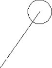
Figure 6.1 Circle and line objects created with the entmake function
Remember that the quote (') function can't evaluate an atom, so you can't use variables in a list that is defined with the quote function. The following examples show how to create an entity data list with the quote function, and then use the resulting list to create an object with the entmake function:
; Creates a new circle at 2.5,3.5 with a radius of 0.75
(entmake '((0 . "CIRCLE") (10 2.5 3.5 0.0) (40 . 0.75)))
; creates a new line from 0,0,0 to 2.5,3.5
(entmake '((0 . "LINE") (10 0.0 0.0 0.0) (11 2.5 3.5 0.0)))
In addition to using the entmake function, you can create objects with the entmakex function. The difference between the entmake and entmakex function is that an owner isn't assigned to the object created with the entmakex function. Owner assignment primarily affects the creation of nongraphical objects, as all graphical objects are assigned to the current space or named layout.
This exercise shows how to create a plan view of a machine screw with a slotted round head (see Figure 6.2):
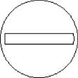
Figure 6.2 Plan view of a #12-24 machine screw, slotted round head
- Create a new drawing.
- At the AutoCAD Command prompt, type the following and press Enter to create a new circle that has a center point of 0,0 and radius of 0.4075.
(entmake '((0 . "CIRCLE") (10 0 0) (40 . 0.4075)))The dotted pair with the DXF group code 10 sets the center point of the circle, and the dotted pair with the DXF group code 40 sets the radius of the circle.
- Type the following and press Enter to create the two lines that define the top and bottom of the slot in the head of the screw:
(entmake '((0 . "LINE") (10 -0.18 0.0275) (11 0.18 0.0275)))
(entmake '((0 . "LINE") (10 -0.18 -0.0275) (11 0.18 -0.0275)))
The dotted pair with the DXF group code 10 sets the start point of the line, and the dotted pair with the DXF group code 11 sets the endpoint of the line.
- Type the following and press Enter to create the two arcs that define the left and right edges of the slot in the head of the screw:
(entmake '((0 . "ARC") (10 0.0032 0) (40 . 0.1853)
           (50 . 2.99261) (51 . 3.29058)))
(entmake '((0 . "ARC") (10 -0.0032 0) (40 . 0.1853)
           (50 . 6.13431) (51 . 0.148875)))
The dotted pair with the DXF group code 10 sets the center point, DXF group code 40 sets the radius, DXF group code 50 sets the start angle (in radians), and DXF group code 51 sets the end angle (in radians) for each arc.
Selecting Objects
AutoLISP enables you to step through the objects in a drawing or allow the user to interactively select one or more objects in the drawing area. Based on the selection technique used, an ename is returned; otherwise, a selection set (ssname) is returned that can contain one or more objects.
Selecting an Individual Object
AutoLISP provides two different techniques that can be used to select an individual object within a drawing—through code or via user interaction. When you want to work with the most recent object or step through all of the objects in a drawing, you don't need any input from the user. The AutoLISP functions entlast and entnext can be used to get an individual object without any input from the user. If you do want to allow the user to interactively select an individual object, you can use the entsel and nentsel functions.
Selecting an Object through Code
The entlast function returns the entity name of the last graphical object added to a drawing and doesn't require any arguments. This function can be helpful in getting the entity name for a new object created with the entmake function.
; Create an arc with a center point of -1,1, radius of 1.5,
; a start angle of 315, and end angle of 135
(entmake '((0 . "ARC")(10 -1.0 1.0 0.0)(40 . 1.5)(50 . 5.49779)(51 . 2.35619)))
((0 . "ARC") (10 -1.0 1.0 0.0) (40 . 1.41421) (50 . 5.49779) (51 . 2.35619))
(setq entityName (entlast))
<Entity name: 7ff72292cc10>
The entnext function allows you to traverse a drawing from the first drawn to most recently added graphical object. When entnext is called without an argument, it returns the ename of the oldest graphical object in the drawing. If the function is passed a valid ename, the ename of the object drawn after the one passed to the function is returned. The following shows the syntax of the entnext function:
(entnext [ename])The ename argument is optional and represents the entity name of an object. The function returns the name of the next object in the drawing. When no ename argument is provided, the entity name of the first graphical object in the drawing is returned.
The following example code uses the entnext function to step through and list the type of each object in the current drawing:
; Lists the DXF group code 0 value for each object in the drawing
(defun c:listobjects ( / )
  (prompt "
Objects in this drawing:")
  (setq entityName (entnext))
  (while entityName
    (prompt (strcat "
" (cdr (assoc 0 (entget entityName)))))
    (setq entityName (entnext entityName))
  )
 (princ)
)
Objects in this drawing:
CIRCLE
DIMENSION
DIMENSION
INSERT
ATTRIB
SEQEND
CIRCLE
VIEWPORT
VIEWPORT
CIRCLE
DIMENSION
ARC
The previous example used the entget function to return an entity data list of an object. I explain how to use this function later, in the “Updating an Object's Properties with an Entity Data List” section.
Selecting an Object Interactively
The user can select a single object in the drawing area using the entsel and nentsel functions. The entsel function returns a list of two values: the entity name of the object selected and the center point of the pick box when the object was selected. nil is returned by the entsel function if an object isn't selected as the result of either the user picking in an empty area of the drawing or pressing Enter.
The nentsel function is similar to entsel except that nentsel allows you to select a subentity within an object, such as an old-style polyline, dimension, or block. When a subentity in an object is selected with the nentsel function, a list of four elements is returned (in this order):
- The entity name of the subentity
- The point picked in the drawing
- A transformation matrix for the subentity
- The entity name of the parent object of the subentity
The following shows the syntax of the entsel and nentsel functions:
(entsel [prompt])
(nentsel [prompt])
The prompt argument is optional and represents the message (a string) that should be displayed to the user when they are asked to select an object. If a prompt is not provided, the default prompt message of Select object: is displayed.
The following examples show how to select an object with the entsel function:
; Prompts the user to select an individual object
(setq entlist (entsel "
Select an object: "))
(<Entity name: 7ff72292cc10> (-0.75599 2.48144 0.0))
; Uses the car function to get the entity name returned by entsel
(setq entityName (car entlist))
<Entity name: 7ff72292cc10>
; Uses the cadr function to get the coordinate value returned by entsel
(setq pickPoint (cadr entlist))
(-0.75599 2.48144 0.0)
Working with Selection Sets
A selection set, sometimes known as a selection set name or ssname for short, is a temporary container that holds a reference to objects in a drawing. AutoLISP represents a selection set with the PICKFIRST data type. You get a selection set, commonly based on the objects in a drawing that the user wants to modify or interact with. For example, when you see the Select objects: prompt AutoCAD is asking you to select the objects in the drawing you want to work with and it gets a selection set containing the objects you selected in return.
In addition to getting a selection set based on user input, you can create a selection set manually and add objects to it. You might want to create a function that steps through a drawing and locates all the objects on a specific layer, and then returns a selection set that the next function can work with. Once a selection set is created, you can add additional objects or remove objects that don't meet the requirements you want to work with. A selection set makes it efficient to query and modify a large number of objects.
Creating a Selection Set
The most common way to create a selection set is to simply prompt the user to select objects in the drawing. The entsel and nentsel functions allow you to select a single object, but typically you will want to allow the user to select more than one object at a time. The ssget function allows the user to interactively select objects in a drawing using the selection methods that are commonly available at the Select objects: prompt. The ssget function can also be used to create a selection set without any user input. The ssget function returns a PICKSET value if at least one object was selected or returns nil if no objects were selected.
The following shows the syntax of the ssget function:
(ssget [method] [point1 [point2]] [points] [filter])Here are the arguments:
methodThemethodargument is optional and represents the selection method that should be used to create the selection set. Many of the selection methods available are similar to those found at theSelect objects:prompt, but additional ones are available from AutoLISP. Table 6.5 lists some of the common selection methods available; for a full list of options search on “ssget” in the AutoCAD Help system.Table 6.5
ssgetselection methodsSelection method Description C Crossing window selection CP Crossing polygon selection L Last object selection P Previous selection set W Window selection WP Window polygon selection X All entities in the database; locked and frozen also :S Single object selection point1Thepoint1argument is an optional point list that is used to select the topmost object in the draw order at the specified point. This argument is also used to specify the first corner of a crossing window or window selection.point2Thepoint2argument is an optional point list that is used to specify the second point for the crossing window or window selection.PointsThepointsargument is an optional list that contains several point lists; it is used to specify the points of a fence, crossing polygon, or window polygon selection.FilterThefilterargument is an optional association list that is similar to an entity data list, but it can also include comparison and grouping operators. Later in this chapter I explain how to create and use selection-set filters; see the sections “Filtering Selected Objects” and “Selecting Objects Based on XData.”
The following examples show how to select objects with the ssget function; the returned values will vary based on the drawing you have open. Open a drawing with some objects in it before trying these examples:
; Freely lets the user to select objects
(setq ss (ssget))
Select objects: Specify the first corner of the selection window
Specify opposite corner: Specify a second point to define the selection window
7 found
Select objects: Press Enter to end object selection
<Selection set: 4d>
; Freely lets the user to select a single object
(setq ssPt (ssget "_:S"))
<Selection set: 1cd>
; Selects the last object drawn at 0,0,0
(setq ssPt (ssget '(0 0 0)))
<Selection set: a9>
1 found
Select objects:
; Selects all objects that intersect 0,0,0 and not just the topmost object
(setq ssC (ssget "_C" '(0 0 0) '(0 0 0)))
<Selection set: be>
3 found
Select objects:
; Selects objects with fence selection crossing (0,0), (0,6), (12,9), and (12,0)
(setq ssF (ssget "_F" '((0 0)(0 6)(12 9)(12 0))))
<Selection set: 190>The ssget function also supports implied selection with the I selection method. Just like many AutoCAD commands, such as move and copy, implied selection allows a user to select objects before starting your custom program. If no objects are selected when you use the statement (ssget "_I"), the ssget function returns nil. You can then test for the nil return value, and if nil is returned, you can prompt the user to select objects.
In addition to using the ssget function to get the objects selected with implied selection, you can use the ssgetfirst function to select objects that have their grips displayed. Grips are displayed only when no custom program or command is active and the user selects objects in the drawing area. The ssgetfirst function returns a list of two elements. The first element always returns nil in recent releases, but in earlier releases it returned a pickfirst value that represented the objects that displayed grips and weren't selected. The second element returns a pickfirst value that represents any objects that are currently selected and have their grips displayed. The ssgetfirst function doesn't accept any arguments.
While the ssgetfirst function is used to get objects that are currently selected and have their grips displayed, you can use the sssetfirst function to select and display the grips for specific objects. The following shows the syntax of the sssetfirst function:
(sssetfirst gripset [pickset])Here are the arguments:
gripsetThegripsetargument no longer affects the outcome of thesssetfirstfunction. In earlier releases, this argument required apicksetvalue that would be used to display the grips of objects but not select them. In recent releases,nilshould always pass this argument.PicksetThepicksetargument is optional and must be apickfirstvalue that contains the objects that should be selected and have their grips displayed.
The following examples show how to select and display the grips for the last object in a drawing with the sssetfirst function:
; Creates a line object that is drawn from 0,0 to -5,5 with a color of red
(entmake '((0 . "line")(10 0.0 0.0)(11 -5.0 5.0)(62 . 1)))
((0 . "line") (10 0.0 0.0) (11 -5.0 5.0) (62 . 1))
; Displays grips for and selects the line that was added
(sssetfirst nil (ssget "L"))
(nil <Selection set: 353>)
; Erases the object with grips displayed
(command "._erase" (cadr (ssgetfirst)) "")
NilManaging Objects in a Selection Set
After the user has been prompted to select objects, the resulting selection set can be revised by adding or removing objects. Objects that aren't in the selection set but are in the drawing can be added to the selection set using the ssadd function. If the user selected an object that shouldn't be in the selection set, it can be removed using the ssdel function. The ssadd and ssdel functions return the selection set that they are passed if the function was successful; otherwise, the function returns nil.
Normally when an object is selected in the drawing, it is added to a selection set once, as duplicate entries aren't allowed. Before adding an object to a selection set with the ssadd function, you can determine if an object is already present in a selection set with the ssmemb function. Duplicate objects in a selection set isn't a problem, but it could cause an issue if your program is extracting information from a drawing or could result in your program taking longer to complete. The ssmemb function returns the ename of the object if it is present in the selection set; otherwise, the function returns nil.
The following shows the syntax of the ssadd, ssdel, and ssmemb functions:
(ssadd ename [ss])
(ssdel ename ss)
(ssmemb ename ss)
The arguments are as follows:
enameWhen used with thessaddorssdelfunction, theenameargument represents the entity name that should be added to or removed from the selection set. When used with thessmembfunction, theenameargument specifies a particular ename to check for in the selection set.SsWhen you want to add, remove, or check for the existence of an entity name in a selection set, thessargument specifies the selection set for the operation. Thessargument is optional for thessaddfunction.
The following examples show how to add and remove objects in a selection set using the ssadd, ssdel, and ssmemb functions:
; Create a line object
(entmake '((0 . "line")(10 0.0 0.0)(11 -5.0 5.0)(62 . 1)))
((0 . "line") (10 0.0 0.0) (11 -5.0 5.0) (62 . 1))
; Add the line to the selection set
(setq ss1 (ssadd (entlast) ss1))
<Selection set: a1>
; Determine if the last graphical entity is in the selection set
(ssmemb (entlast) ss1)
<Entity name: 7ff6a1704f00>
; Remove the last entity from the selection set
(ssdel (entlast) ss1)
<Selection set: a1>
; Determine if the last graphical entity is in the selection set
(ssmemb (entlast) ss1)
nil
Stepping through a Selection Set
Selection sets contain the objects the user selected in the drawing for query or modification and might include one to several thousand objects. You can use the repeat or while looping functions in combination with the sslength and ssname functions to step through and access each object in a selection set. The sslength function returns the number of objects in a selection set as an integer, whereas the ssname function is used to return the entity name of an object located at a specific index within a selection set. The index of the first object in a selection set is 0. As part of a looping statement, you increment an integer value by 1 to get the next object until you reach the last object in the selection set. If an object isn't at the specified index in a selection set when using the ssname function, nil is returned.
The following shows the syntax of the sslength function:
(sslength ss)The ss argument represents the selection set from which you want to get the number of objects.
The following shows the syntax of the ssname function:
(ssname ss index)Its arguments are as follows:
ssThessargument represents the selection set from which you want to get an entity name at a specific index.IndexTheindexargument represents the location within the selection set specified by thessargument that has the object you want to get. 0 is the index of the first object in the selection set.
The following examples show how to get the number of objects in a selection set and get an object from a selection set with the sslength and ssname functions:
; Get a selection set
(setq ssNew (ssget))
Select objects: Specify the first corner of the object-selection window
Specify opposite corner: Specify the other corner of the object-selection window
9 found
Select objects: Press Enter to end object selection
<Selection set: 13>
; Output the number of objects in a selection set
(prompt (strcat "
Selection set length: " (itoa (sslength ssNew))))(princ)
Selection set length: 9
; Get the entity name of the first object in the selection set
(ssname ssNew 0)
<Entity name: 7ff63f005d90>
This exercise shows how to create and step through a selection set:
- Open a drawing with some objects, or create a new drawing and then add some objects to the drawing.
- At the AutoCAD Command prompt, type the following and press Enter to create a selection set and assign it to the
ssetvariable:(prompt " Select objects to list: ") (setq sset (ssget)) - Type the following and press Enter to create a new circle and then add the new circle to the selection set:
(entmake '((0 . "circle")(10 0.0 0.0)(40 . 2)))
(if (= (ssmemb (entlast) sset) nil)
  (setq sset (ssadd (entlast) sset))
)
While the circle shouldn't be part of the objects you selected, the code shows how to use a comparison to test the results of the
ssmembfunction. The new object is added only if it isn't already part of the selection set. - Type the following and press Enter to display the number of objects in the selection set:
(prompt (strcat " Objects in selection set: " (itoa (sslength sset))))(princ) - Type the following and press Enter to change the color of each object in the selection set:
(setq cnt 0 clr 1)
(while (> (sslength sset) cnt)
  (command "._change" (ssname sset cnt) "" "_p" "_c" clr "")
  (setq cnt (1+ cnt))
  (setq clr (1+ clr))
  (if (> clr 9)(setq clr 1))
)(princ)
The colors assigned to the objects range from ACI 1 through 9, and reset back to 1 when the counter reaches 10.
Filtering Selected Objects
When selecting objects with the ssget function, you can control which objects are added to the selection set. A selection filter allows you to select objects of a specific type or even objects with certain property values. Selection filters are made up of dotted pairs and are similar to an entity data list. For example, the following selection filter will select all circles on the layer holes:
'((0 . "circle")(8 . "holes"))As I mentioned earlier, the DXF group code 0 represents an object's name and the DXF group code 8 represents the name of the layer an object is placed on.
In addition to object names and properties, a selection filter can include logical grouping and comparison operators to create complex filters. Complex filters can be used to allow for the selection of several object types, such as both text and mtext objects, or allow for the selection of circles with a radius in a given range. Logical grouping and comparison operators are specified by string values with the DXF group code -4. For example, the following selection filter allows for the selection of circles with a radius in the range of 1 to 5:
'((0 . "circle")
  (-4 . "<and")(-4 . "<=")(40 . 5.0)(-4 . ">=")(40 . 1.0)(-4 . "and>"))
Selection filters support four logical grouping operators: and, or, not, and xor. Each logical grouping operator used in a selection filter must have a beginning and an ending operator. Beginning operators start with the character < and ending operators end with the character >. In addition to logical operators, you can use seven different comparison operators in a selection filter to evaluate the value of a property: = (equal to), != (not equal to), < (less than), > (greater than), <= (less than or equal to), >= (greater than or equal to), and * (wildcard for string comparisons).
After defining a selection filter, you then pass it to the filter argument of the ssget function.
This exercise shows how to use selection filters with the ssget function:
- Create a new drawing. Add some circles, arcs, and lines to the drawing.
- At the AutoCAD Command prompt, type
(setq ssCircles (ssget '((0 . "circle"))))and press Enter. - At the
Select objects:prompt, select all the objects in the drawing. Notice only the circles are highlighted. Press Enter to end object selection. - Type
(command "._change" ssCircles "" "_p" "_c" 1 "")and press Enter to change the color of all circles to red. - At the AutoCAD Command prompt, type
(setq ssArcsLines (ssget '((-4 . "<or")(0 . "arc")(0 . "line")(-4 . "or>"))))and press Enter. Select some of the lines and arcs in the drawing. - Type
(command "._change" ssArcsLines "" "_p" "_c" 3 "")and press Enter to change the color of the selected objects to green.
Modifying Objects
The majority of time spent on a design isn't related to creating new objects, but rather to modifying the objects that are already in a drawing. When you need to modify an object, you can use an AutoCAD command with the command function or directly with AutoLISP functions. Directly modifying an object provides you with more choices in the properties you can change and gives you more flexibility than using commands.
Modifying objects with AutoCAD commands is similar to creating new objects, with the exception of the way you pass objects to the command. Based on the command, you will need to pass one of the following to the Select object: or Select objects: prompt to select objects:
- Entity Name (ename) An ename can be used when a command expects or you want to modify a single object.
- Selection Set (ssname) An ssname can be used to pass several objects to a command that can modify one or more objects.
I explained how to select objects and work with selection sets in the “Selecting Objects” section earlier in this chapter.
The following are examples that demonstrate how to modify objects with AutoCAD commands:
; Changes the selected objects to the color red
(prompt "
Select objects to change to red: ")
(setq ss (ssget))
(command "._change" ss "" "_p" "_c" 1 "")
; Scale the last graphical object by a user-defined base point and a factor of 2
(command "._scale" (entlast) "" PAUSE 2)
In this section, I explain how to work with entity names and directly modify an object without using the command function. The properties of an object can be queried or edited one at a time, or you can manipulate several properties of an object by changing the entity data list that represents the object.
Listing and Changing the Properties of an Object Directly
AutoLISP offers two different methods for modifying the properties of an object directly. The easier of the two methods is to use the object property functions that were introduced with AutoCAD 2012. These functions require less code than the legacy approach of getting and manipulating the entity data list of an object. The property-related functions are less cryptic than entity data list manipulation as well, because you don't need to understand the various DXF group codes associated with a specific object. The downside to these functions is that they work only with AutoCAD 2012 and later, so if you need to support an earlier release you will need to manipulate entity data lists (which I cover in the next section).
Table 6.6 lists the AutoLISP functions available in AutoCAD 2012 and later that can be used to list, get, and set the properties of an object.
Table 6.6 AutoLISP object property functions
| Function | Description |
dumpallproperties |
Returns all of the properties for the specified object |
getpropertyvalue |
Returns the current value of an object's property |
setpropertyvalue |
Assigns a value to an object's property |
ispropertyreadonly |
Returns T or nil based on whether an object property is read-only |
Listing Object Properties
The dumpallproperties function outputs the properties and their current values for an object to the command-line window. Some property values, such as StartPoint for a line or Position of a block reference, can be output as a single value or as three individual values.
The following shows the syntax of the dumpallproperties function:
(dumpallproperties ename [mode])Its arguments are as follows:
enameTheenameargument represents the entity name of the object for which you want to list properties.ModeThemodeargument is optional and represents how data types such asAcGePoint3dandAcGeVector3dare output. Whenmodeis 0, a property such as Center is displayed as a single entry and not separate entries for the X, Y, and Z values of a property. For example, the following output is of the center point for a circle that has X, Y, and Z components to the value. The output shows all three components as part of a single property named Center.Center (type: AcGePoint3d) (LocalName: Center X;Center Y;Center Z) = 0.000000 5.000000 0.000000
A value of 1 for mode displays each element of a value as separate entries. This is the default behavior when mode isn't provided. The following output is of the same center point as before, but notice all three components of the point are expressed as separate properties with unique names: Center/X, Center/Y, and Center/Z.
Center/X (type: double)  (LocalName: Center X) = 0.000000
Center/Y (type: double)  (LocalName: Center Y) = 5.000000
Center/Z (type: double)  (LocalName: Center Z) = 0.000000
The following examples show how to output the properties of an object with the dumpallproperties function:
; Properties are output as a single entry
(dumpallproperties (entlast) 1)
; Properties are output as separate entries
(dumpallproperties (entlast))
Here is an example of the output created by the dumpallproperties function for a circle object. The output was generated with the expression (dumpallproperties (entlast)):
Begin dumping object (class: AcDbCircle)
Annotative (type: bool)  (LocalName: Annotative) = Failed to get value
AnnotativeScale (type: AcString)  (RO)
     (LocalName: Annotative scale) = Failed to get value
Area (type: double)  (RO)  (LocalName: Area) = 12.566371
BlockId (type: AcDbObjectId)  (RO) = 7ff618a039f0
CastShadows (type: bool) = 0
Center/X (type: double)  (LocalName: Center X) = 0.000000
Center/Y (type: double)  (LocalName: Center Y) = 5.000000
Center/Z (type: double)  (LocalName: Center Z) = 0.000000
Circumference (type: double)  (LocalName: Circumference) = 12.566371
ClassName (type: AcString)  (RO) =
Closed (type: bool)  (RO)  (LocalName: Closed) = Failed to get value
CollisionType (type: AcDb::CollisionType)  (RO) = 1
Color (type: AcCmColor)  (LocalName: Color) = BYLAYER
Diameter (type: double)  (LocalName: Diameter) = 4.000000
EndParam (type: double)  (RO) = 6.283185
EndPoint/X (type: double)  (RO)  (LocalName: End X) = Failed to get value
EndPoint/Y (type: double)  (RO)  (LocalName: End Y) = Failed to get value
EndPoint/Z (type: double)  (RO)  (LocalName: End Z) = Failed to get value
ExtensionDictionary (type: AcDbObjectId)  (RO) = 0
Handle (type: AcDbHandle)  (RO) = 1f9
HasFields (type: bool)  (RO) = 0
HasSaveVersionOverride (type: bool) = 0
Hyperlinks (type: AcDbHyperlink*)
IsA (type: AcRxClass*)  (RO) = AcDbCircle
IsAProxy (type: bool)  (RO) = 0
IsCancelling (type: bool)  (RO) = 0
IsEraseStatusToggled (type: bool)  (RO) = 0
IsErased (type: bool)  (RO) = 0
IsModified (type: bool)  (RO) = 0
IsModifiedGraphics (type: bool)  (RO) = 0
IsModifiedXData (type: bool)  (RO) = 0
IsNewObject (type: bool)  (RO) = 0
IsNotifyEnabled (type: bool)  (RO) = 0
IsNotifying (type: bool)  (RO) = 0
IsObjectIdsInFlux (type: bool)  (RO) = 0
IsPeriodic (type: bool)  (RO) = 1
IsPersistent (type: bool)  (RO) = 1
IsPlanar (type: bool)  (RO) = 1
IsReadEnabled (type: bool)  (RO) = 1
IsReallyClosing (type: bool)  (RO) = 1
IsTransactionResident (type: bool)  (RO) = 0
IsUndoing (type: bool)  (RO) = 0
IsWriteEnabled (type: bool)  (RO) = 0
LayerId (type: AcDbObjectId)  (LocalName: Layer) = 7ff618a03900
LineWeight (type: AcDb::LineWeight)  (LocalName: Lineweight) = -1
LinetypeId (type: AcDbObjectId)  (LocalName: Linetype) = 7ff618a03950
LinetypeScale (type: double)  (LocalName: Linetype scale) = 1.000000
LocalizedName (type: AcString)  (RO) = Circle
MaterialId (type: AcDbObjectId)  (LocalName: Material) = 7ff618a03de0
MergeStyle (type: AcDb::DuplicateRecordCloning)  (RO) = 1
Normal/X (type: double)  (RO)  (LocalName: Normal X) = 0.000000
Normal/Y (type: double)  (RO)  (LocalName: Normal Y) = 0.000000
Normal/Z (type: double)  (RO)  (LocalName: Normal Z) = 1.000000
ObjectId (type: AcDbObjectId)  (RO) = 7ff618a0c090
OwnerId (type: AcDbObjectId)  (RO) = 7ff618a039f0
PlotStyleName (type: AcString)  (LocalName: Plot style) = ByLayer
Radius (type: double)  (LocalName: Radius) = 2.000000
ReceiveShadows (type: bool) = 0
ShadowDisplay (type: AcDb::ShadowFlags)  (RO)
     (LocalName: Shadow Display) = Failed to get value
StartParam (type: double)  (RO) = 0.000000
StartPoint/X (type: double)  (RO)  (LocalName: Start X) = Failed to get value
StartPoint/Y (type: double)  (RO)  (LocalName: Start Y) = Failed to get value
StartPoint/Z (type: double)  (RO)  (LocalName: Start Z) = Failed to get value
Thickness (type: double)  (LocalName: Thickness) = 0.000000
Transparency (type: AcCmTransparency)  (LocalName: Transparency) = 0
Visible (type: AcDb::Visibility) = 0
End object dump
Now that you have seen an example output of an object with the dumpallproperties function, it is time to take a closer look at an individual property. The following line shows the Area property from the previous output. Table 6.7 explains the elements.
Area (type: double) (RO) (LocalName: Area) = 12.566371Table 6.7 dumpallproperties Area property description
| Item | Description |
Area |
The global name of the object's property. |
(type: double) |
The data type for the value for the property. |
(RO) |
The property is read-only. |
(LocalName: Area) |
The local name of the object property. |
= 12.566371 |
The value of the property. |
Getting and Setting the Value of an Object Property
The getpropertyvalue and setpropertyvalue functions allow you to set an object's property. Use the dumpallproperties function on an ename to see the properties available for an object and the type of data that is expected.
The following shows the syntax of the getpropertyvalue and setpropertyvalue functions:
(getpropertyvalue ename property)
(getpropertyvalue ename collection index subproperty)
(setpropertyvalue ename property value)
(setpropertyvalue ename collection index subproperty value)
Here are the arguments:
enameTheenameargument represents the entity name of the object for which you want to get or set a property value.PropertyUse thepropertyargument to specify a single-value property.CollectionUse thecollectionargument to specify a property that contains more than one value, such as vertices of a polyline.IndexUse theindexargument to specify an item within a property collection.SubpropertyUse thesubpropertyargument to specify a subproperty within a property collection.ValueThevalueargument represents the value you want to assign the property.
The following examples show how to get and set the property values of a circle and a polyline with the getpropertyvalue and setpropertyvalue functions:
; Creates a circle and polyline
(command "._circle" "0,0" 1)
(setq circ (entlast))
(command "._pline" "2,3" "1,4" "-3,-2" "")
(setq pline (entlast))
; Outputs the radius of the circle
(prompt (strcat "
Radius: " (rtos (getpropertyvalue circ "radius"))))
Radius: 1.0000nil
; Outputs the last vertex of the polyline
(prompt (strcat "
Vertex 3: "
  (vl-princ-to-string (getpropertyvalue pline "vertices" 2 "position"))
))
Vertex 3: (-3.0 -2.0 0.0)nil
; Changes the radius of the circle
(setpropertyvalue circ "radius" 0.5)
nil
; Changes the position of the polyline's last vertex to the center of the circle
(setq cenPt (getpropertyvalue circ "center"))
(setpropertyvalue pline "vertices" 2 "position" cenPt)
nil
Before you try to change a property value with setpropertyvalue, use the ispropertyreadonly function to determine if the property is read-only. ispropertyreadonly returns 1 if a property is read-only; 0 is returned when a property can be changed. The following shows the syntax of the ispropertyreadonly function:
(ispropertyreadonly ename property)
(ispropertyreadonly ename collection index subproperty)
The following examples show how to determine if a property for a line object is read-only with the ispropertyreadonly:
; Creates a line
(command "._line" "2,2" "5,6" "")
(setq line (entlast))
; Tests to see if the Angle property is read-only
(ispropertyreadonly line "angle")
1
; Tests to see if the StartPoint property is read-only
(ispropertyreadonly line "startpoint")
0
This exercise shows how to modify the properties of a circle, line, and text object:
- Create a new drawing.
- Draw a circle (center at 4,5 and a radius of 3), a line (starts at -1,2 and ends at 8,15), and a single-line text object (insertion point of 0,0, a justification of middle center, a height of 4, and a value of A). The left side of Figure. 6.3 shows what the objects look like before they are modified.
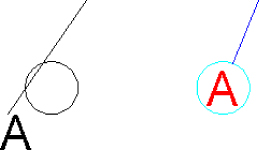
Figure 6.3 Basics of a callout balloon
- At the AutoCAD Command prompt, type the following, pressing Enter after each line and selecting the object mentioned in the prompt:
(setq circ (car (entsel " Select circle: "))) (setq line (car (entsel " Select line: "))) (setq text (car (entsel " Select text: "))) - Type
(dumpallproperties circ 1)and press Enter to display the properties of the circle. Do the same with thelineandtextvariables. - Press F2 on Windows or Fn-F2 on Mac OS to expand the command-line window (or display the Text History window on Windows if the command-line window is docked). Review the properties and values of the objects.
- Type the following and press Enter to change the circle's color to cyan, the line's color to blue, and the text's color to red:
(setpropertyvalue circ "color" 4) (setpropertyvalue line "color" 5) (setpropertyvalue text "color" 1) - Type the following and press Enter to change the line's start point and the text's alignment point to the circle's center point:
(setpropertyvalue line "startpoint" (getpropertyvalue circ "center")) (setpropertyvalue text "alignmentpoint" (getpropertyvalue circ "center")) - Type the following and press Enter to shorten the line so it intersects with the circle's radius:
(setq ang (angle (getpropertyvalue line "startpoint")
                 (getpropertyvalue line "endpoint")
))
(setq newPt (polar (getpropertyvalue circ "center")
                   ang
                   (getpropertyvalue circ "radius")
))
(setpropertyvalue line "startpoint" newPt)
The three modified objects should now look like those on the right side of Figure 6.3.
Updating an Object's Properties with an Entity Data List
Although the functions I mentioned in the previous section make working with object properties easier in recent releases, you should also understand how to modify the properties of an object with an entity data list. There are three main reasons why I recommend this:
- Older programs modify objects using entity data lists; understanding how to update entity data lists will make it easier for you to update an existing program.
- AutoCAD releases earlier than AutoCAD 2012 only support editing the properties of objects through entity data lists.
- Entity data lists are used to create and define selection filters.
The entget function is used to return the entity data list of an object. Once you have an entity data list, you can then use the assoc function to locate the dotted pair that has the DXF group code as the key element you are interested in querying or modifying. After a dotted pair is retuned, you can then use the car function to get the key element of the list and the cdr function to get the value element of the dotted pair.
If you want to replace a dotted pair in an entity data list to change the value of a property, use the subst function. Then, after you update an entity data list, the changed entity data list must be committed to the object with the entmod function. After calling entmod, you should call the entupd function with the same object that was passed to the entget function to update the object's graphics onscreen.
The following shows the syntax of the entget, entmod, and entupd functions:
(entget ename [apps])
(entmod ename)
(entupd ename)
Here are the arguments:
enameTheenameargument specifies the entity name of the object you want update or to get an entity data list for.AppsTheappsargument is optional; it is a string value that specifies the application name of an extended data (XData) list that you want to retrieve. XData is custom information that can be attached to an object, such as a link to an external data source or date when an object was revised, and is similar to an entity data list associated with an ename. If an XData list with the application name is attached to the object, a list with both the entity data and XData is returned. Otherwise, just the entity data list for the object is returned. For more information on XData, see the “Extending the Information of an Object” section later in this chapter.
The following examples show how to get an entity data list with entget, modify an entity data list with entmod, and update an object in the drawing area with entupd:
; Creates a new ellipse and gets the new object's entity name
(entmake '((0 . "ELLIPSE") (100 . "AcDbEntity") (100 . "AcDbEllipse")
           (10 6.0 2.0 0.0) (11 -4.0 0.0 0.0)
           (40 . 0.5) (41 . 0.0) (42 . 6.28319)))
(setq entityName (entlast))
<Entity name: 7ff6bc905dc0>
; Gets the entity data list for the last object, which is the ellipse
(setq entityData (entget entityName))
((-1 . <Entity name: 7ff6bc905dc0>) (0 . "ELLIPSE")
 (330 . <Entity name: 7ff6bc9039f0>) (5 . "1D4") (100 . "AcDbEntity")
 (67 . 0) (410 . "Model") (8 . "0") (100 . "AcDbEllipse")
 (10 6.0 2.0 0.0) (11 -4.0 0.0 0.0) (210 0.0 0.0 1.0) (40 . 0.5)
 (41 . 0.0) (42 . 6.28319))
; Gets the object's insertion/center point, center of the ellipse
(setq dxfGroupCode10 (assoc 10 entityData))
(10 6.0 2.0 0.0)
; Gets the object's color; in this case nil is returned as a color isn't assigned
(setq dxfGroupCode62 (assoc 62 entityData))
nil
; Changes the object's center point to 0,0
(setq entityData (subst '(10 0.0 0.0 0.0) dxfGroupCode10 entityData))
(10 6.0 2.0 0.0)
; Appends a dotted pair to change the object's color
(setq entityData (append entityData '((62 . 3))))
; Modifies the object with the revised entity data list
(entmod entityData)
(entupd entityName)
Listing 6.1 is a set of two custom functions that simplify the process of updating an object using entity data lists and DXF group codes.
The custom functions in Listing 6.1 are used in the next exercise.
This exercise shows how to modify the properties of a circle, line, and text object:
- Create a new drawing.
- Use the
apploadcommand to load thech06_listings.lspfile once it is downloaded from www.sybex.com/go/autocadcustomization. - Draw a circle (center at 4,5 and a radius of 3), a line (starts at -1,2 and ends at 8,15), and a single-line text object (insertion point of 0,0, a justification of middle center, a height of 4, and a value of A). Refer back to Figure 6.3; the left side shows what the objects look like before they are modified.
- At the AutoCAD Command prompt, type the code in Listing 6.1. This will allow you to use the custom functions to make it easier to modify the properties of an object with an entity data list.
- Type the following, pressing Enter after each line, and select the object mentioned in the prompt.
(setq circ (car (entsel " Select circle: "))) (setq line (car (entsel " Select line: "))) (setq text (car (entsel " Select text: "))) - Type
(dumpallproperties circ 1)and press Enter to display the properties of the circle. Do the same with thelineandtextvariables. - Press F2 on Windows or Fn-F2 on Mac OS to expand the command-line window (or display the Text History window on Windows if the command-line window is docked). Review the properties and values of the objects.
- Type the following and press Enter to change the circle's color to cyan, the line's color to blue, and the text's color to red:
(Set-DXF-Value circ 62 4) (Set-DXF-Value line 62 5) (Set-DXF-Value text 62 1) - Type the following and press Enter to change the line's start point and the text's alignment point to the circle's center point:
(Set-DXF-Value line 10 (Get-DXF-Value circ 10)) (Set-DXF-Value text 11 (Get-DXF-Value circ 10)) - Type the following and press Enter to shorten the line so it intersects with the circle's radius:
(setq ang (angle (Get-DXF-Value line 10)
                 (Get-DXF-Value line 11)
))
(setq newPt (polar (Get-DXF-Value circ 10)
                   ang
                   (Get-DXF-Value circ 40)
))
(Set-DXF-Value line 10 newPt)
The three modified objects should now look like those on the right side of Figure 6.3.
Deleting an Object
An object that is no longer needed can be deleted from a drawing with the AutoLISP entdel function. Deleting an object from a drawing with the entdel function removes it from the display but doesn't remove the object from the drawing immediately. It flags an object for removal; the object is removed when the drawing is saved and then closed. You can use the entdel function a second time to restore the object while the drawing remains open. Using the AutoCAD u or undo command will also restore an object that was flagged for removal with the entdel function. Objects removed with the erase command can also be restored with the entdel function.
The following shows the syntax of the entdel function:
(entdel ename)The ename argument represents the entity name of the object to flag for deletion or restore.
The following examples show how to remove an object with the entdel function:
; Gets the last object added to the drawing
(setq en (entlast))
<Entity name: 7ff618a0be20>
; Deletes the object assigned to the en variable
(entdel en)
<Entity name: 7ff618a0be20>
; Restores the object assigned to the en variable
(entdel en)
<Entity name: 7ff618a0be20>
Highlighting Objects
Object highlighting is the feedback technique that AutoCAD uses to indicate which objects have been selected in the drawing area and are ready to be interacted with or modified. While highlighting is a great way to let a user know which objects will be modified, it can also impact the performance of a program when a large number of objects are selected. You can turn off general object-selection highlighting with the highlight system variable.
The AutoLISP redraw function, not the same as the redraw command, can be used to highlight individual objects. Highlighting generated by the redraw function can be undone, either with the redraw function or the AutoCAD regen command. In addition to highlighting an object, the redraw function can be used to temporarily hide and then redisplay an object.
The following shows the syntax of the redraw function:
(redraw [ename [mode]])Here are the arguments:
enameTheenameargument represents the entity name of the object to highlight or display.ModeThemodeargument is an integer that specifies the highlight or display state of the object. Use the values1(show) and2(hide) to control the display of an object. The values3(on) and4(off) control the highlighting of the object.
The following examples show how to highlight and display an object with the redraw function:
; Highlights the last graphical object in the drawing
(redraw (entlast) 3)
; Unighlights the object
(redraw (entlast) 4)
; Hides the object
(redraw (entlast) 2)
; Shows the object
(redraw (entlast) 1)
Working with Complex Objects
Some objects in AutoCAD represent basic geometry such as circles and lines, whereas other objects are complex and made up of several objects. Complex objects require a bit more work to create and modify with AutoLISP. The two most common complex objects that you will find yourself working with are polylines and block references.
Creating and Modifying Polylines
AutoCAD drawings can contain two different types of polylines; old-style (legacy) and lightweight. Old-style polylines were the first type of polylines that were introduced in an early release of AutoCAD. An old-style polyline is composed of several objects: a main polyline object, vertex objects that define each vertex of the polyline, and a seqend object that defines the end of the polyline. Old-style polylines can be 2D or 3D and contain straight or curved segments.
Lightweight polylines, introduced with AutoCAD Release 14, take up less memory than old-style polylines but are 2D only. All 3D polylines are created using old-style polylines. Unlike old-style polylines, multiple objects aren't used to define a lightweight polyline. Most polylines created since AutoCAD Release 14 are most likely of the lightweight type. The plinetype system variable controls the type of polyline that is created with the pline command.
The following example creates an old-style polyline that has the coordinate values (0 0), (5 5), (10 5), and (10 0) with the entmake function:
; Creates the base polyline object
(entmake '((0 . "POLYLINE") (100 . "AcDbEntity") (100 . "AcDb2dPolyline")
           (10 0.0 0.0 0.0) (70 . 1)))
((0 . "POLYLINE") (100 . "AcDbEntity") (100 . "AcDb2dPolyline") (10 0.0 0.0 0.0)
 (70 . 1))
; Adds the first vertex to the polyline at 0,0
(entmake '((0 . "VERTEX") (100 . "AcDbEntity") (100 . "AcDbVertex")
           (100 . "AcDb2dVertex") (10 0.0 0.0 0.0) (91 . 0) (70 . 0)
           (50 . 0.0)))
((0 . "VERTEX") (100 . "AcDbEntity") (100 . "AcDbVertex") (100 . "AcDb2dVertex")
 (10 0.0 0.0 0.0) (91 . 0) (70 . 0) (50 . 0.0))
; Adds the next vertex to the polyline at 5,5
(entmake '((0 . "VERTEX") (100 . "AcDbEntity") (100 . "AcDbVertex")
           (100 . "AcDb2dVertex") (10 5.0 5.0 0.0) (91 . 0) (70 . 0)
           (50 . 0.0)))
((0 . "VERTEX") (100 . "AcDbEntity") (100 . "AcDbVertex") (100 . "AcDb2dVertex")
 (10 5.0 5.0 0.0) (91 . 0) (70 . 0) (50 . 0.0))
; Adds the next vertex to the polyline at 10,5
(entmake '((0 . "VERTEX") (100 . "AcDbEntity") (100 . "AcDbVertex")
           (100 . "AcDb2dVertex") (10 10.0 5.0 0.0) (91 . 0) (70 . 0)
           (50 . 0.0)))
((0 . "VERTEX") (100 . "AcDbEntity") (100 . "AcDbVertex") (100 . "AcDb2dVertex")
 (10 10.0 5.0 0.0) (91 . 0) (70 . 0) (50 . 0.0))
; Adds the next vertex to the polyline at 10,0
(entmake '((0 . "VERTEX") (100 . "AcDbEntity") (100 . "AcDbVertex")
           (100 . "AcDb2dVertex") (10 10.0 0.0 0.0) (91 . 0) (70 . 0)
           (50 . 0.0)))
((0 . "VERTEX") (100 . "AcDbEntity") (100 . "AcDbVertex") (100 . "AcDb2dVertex")
 (10 10.0 0.0 0.0) (91 . 0) (70 . 0) (50 . 0.0))
; Adds the next vertex to the polyline at 10,0
(entmake '((0 . "SEQEND") (100 . "AcDbEntity")))
((0 . "SEQEND") (100 . "AcDbEntity"))
When you want to modify an old-style polyline, get the polyline object and then use the entnext function to step to the first vertex until you get to the seqend object. Using a while looping statement is the best way to step through the drawing looking for each vertex of the polyline. Continue looping until you encounter a dotted pair with a DXF group code 0 and a value of "SEQEND".
Listing 6.2 is a custom function that demonstrates how to get each of the subobjects of an old-style polyline with the while function.
The output generated by the custom ListOSPolyline function from Listing 6.2 will be similar to the following:
POLYLINE
VERTEX
(10 0.0 0.0 0.0)
VERTEX
(10 5.0 5.0 0.0)
VERTEX
(10 10.0 5.0 0.0)
VERTEX
(10 10.0 0.0 0.0)
SEQEND
For more information on the DXF entities polyline, vertex, and seqend, use the AutoCAD Help system. Search on the type of object you want to learn more about and be sure to include “DXF” as a keyword in the search. For example, the keyword search on the polyline object would be “polyline DXF.”
The following example creates a lightweight polyline that has the coordinate values (0 0), (5 5), (10 5), and (10 0) with the entmake function:
; Create a polyline object drawn along the path (0 0), (5 5), (10 5), and (10 0)
(entmake '((0 . "LWPOLYLINE") (100 . "AcDbEntity") (100 . "AcDbPolyline")
           (90 . 4) (70 . 1) (43 . 0) (10 0 0) (10 5 5) (10 10 5) (10 10 0)))
((0 . "LWPOLYLINE") (100 . "AcDbEntity") (100 . "AcDbPolyline") (90 . 4) (70 . 1)
 (43 . 0) (10 0 0) (10 5 5) (10 10 5) (10 10 0))
The DXF group code 10 in the previous example appears multiple times in the entity data list. Each dotted pair with a DXF group code 10 represents a vertex in the polyline, and they appear in the order in which the polyline should be drawn. For more information on the lwpolyline DXF entity, search on “lwpolyline DXF” in the AutoCAD Help system.
The approaches to updating and querying an old-style and lightweight polyline vary, so you will need to handle each type using conditional statements in your programs. You can use the getpropertyvalue and setpropertyvalue functions to work with the Vertices property of both types of polylines to simplify the code you might need to write.
Creating and Modifying with Block References
Block references are often misunderstood by new (and even experienced) AutoLISP developers. Blocks are implemented as two separate objects: block definitions and block references. Block definitions are nongraphical objects that are stored in a drawing and contain the geometry and attribute definitions that make up how the block should appear and behave in the drawing area. A block definition can also contain custom properties and dynamic properties.
A block reference displays an instance, not a copy, of the geometry from a block definition; the geometry exists only as part of the block definition, with the exception of attributes. Attribute definitions that are part of a block definition are added to a block reference as attributes unless the attribute definition is defined as a constant attribute. Constant attributes are parts of the geometry inherited from a block definition and aren't part of the block reference.
When creating a block reference with AutoLISP, as opposed to inserting it with the insert command, you are responsible for adding any attributes to the block reference that aren't designated as constant within the block definition. Like the old-style polyline, block references use the seqend object to designate the end of an insert object. Between the insert and seqend objects of a block reference are attrib objects that represent the attribute references that aren't set as constant and must be added to a block reference.
Since attributes must be added to a block reference, it is possible to have a block definition that contains attribute definitions and a block reference that points to that block definition without any attributes. It is also possible to have a block reference that has attributes attached to it and a block reference that doesn't have any attribute definitions.
The following code adds a block definition named RoomNum (see Figure 6.4) to a drawing that has a single attribute with the tag ROOM#:
; Creates the block definition RoomNum
(entmake (list (cons 0 "BLOCK") (cons 2 "roomnum")
               (cons 10 (list 18.0 9.0 0.0)) (cons 70 2)))
; Creates the rectangle for around the block attribute
(entmake (list (cons 0 "LWPOLYLINE") (cons 100 "AcDbEntity")
               (cons 100 "AcDbPolyline") (cons 90 4) (cons 70 1)
               (cons 43 0) (cons 10 (list 0.0 0.0 0.0))
               (cons 10 (list 36.0 0.0 0.0)) (cons 10 (list 36.0 18.0 0.0))
               (cons 10 (list 0.0 18.0 0.0))))
; Adds the attribute definition
(entmake (list (cons 0 "ATTDEF") (cons 100 "AcDbEntity")
               (cons 100 "AcDbText") (cons 10 (list 18.0 9.0 0.0))
               (cons 40 9.0) (cons 1 "L000") (cons 7 "Standard")
               (cons 72 1) (cons 11 (list 18.0 9.0 0.0))
               (cons 100 "AcDbAttributeDefinition") (cons 280 0)
               (cons 3 "ROOM#") (cons 2 "ROOM#") (cons 70 0)
               (cons 74 2) (cons 280 1)))
; Ends block definition
(entmake (list (cons 0 "ENDBLK")))
Once the block definition is created, you can then use the following code to add a block reference to a drawing based on a block named RoomNum:
; Creates a block reference based on the block definition BlockNumber at 1.0,-0.5
(entmake '((0 . "INSERT")(100 . "AcDbEntity")(100 . "AcDbBlockReference")
           (66 . 1) (2 . "roomnum") (10 1.0 -0.5 0.0)))
((0 . "INSERT")(100 . "AcDbEntity")(100 . "AcDbBlockReference") (66 . 1)
 (2 . "RoomNum") (10 1.0 -0.5 0.0))
; Creates an attribute reference with the tag ROOM# and adds it to the block
(entmake '((0 . "ATTRIB") (100 . "AcDbEntity") (100 . "AcDbText")
          (10 0.533834 -0.7 0.0) (40 . 9.0) (1 . "101") (7 . "Standard")
          (71 . 0) (72 . 1) (11 1.0 -0.5 0.0) (100 . "AcDbAttribute")
          (280 . 0) (2 . "ROOM#") (70 . 0) (74 . 2) (280 . 1)))
(entmake '((0 . "ATTRIB") (100 . "AcDbEntity") (100 . "AcDbText")
           (10 0.533834 -0.7 0.0) (40 . 0.4) (1 . "101") (7 . "Standard")
           (71 . 0) (72 . 1) (11 1.0 -0.5 0.0) (100 . "AcDbAttribute")
           (280 . 0) (2 . "ROOM#") (70 . 0) (74 . 2) (280 . 1)))
; Adds the end marker for the block reference
(entmake ' ((0 . "SEQEND") (100 . "AcDbEntity")))
((0 . "SEQEND") (100 . "AcDbEntity"))
Figure 6.4 RoomNum block reference inserted with AutoLISP
If you want to extract the values of the attributes attached to a block, you must get the constant attribute values from the block definition and the nonconstant attribute values that are attached as part of the block reference. You use the entnext function to step through each object in a block definition and block reference, collecting information from the reference objects. All attribute definitions (attdef) or attribute reference (attrib) objects must be read until the last or seqend object is encountered.
Listing 6.3 shows a custom function that demonstrates how to step through a block reference and its block definition with the while function. You must load the custom functions in Listing 6.2 before executing the code in Listing 6.3. The code in Listing 6.2 and Listing 6.3 can be found in the ch06_code_listings.lsp file that is available for download from this book's website.
Here is an example of the output generated by the custom ListBlockAtts function:
*Block Reference*
INSERT
Block name: RoomNumber
ATTRIB
Tag: ROOM#
Value: 101
SEQEND
*Block Definition*In addition to using entity data lists to query and modify block references, you can use the getpropertyvalue and setpropertyvalue functions. You learned about those functions in the “Listing and Changing the Properties of an Object Directly” section earlier in this chapter.
Extending an Object's Information
Each object in a drawing has a pre-established set of properties that define how that object should appear or behave. These properties are used to define the size of a circle or the location of a line within a drawing. Although you can't add a new property to an object with AutoLISP, you can append custom information to an object. The custom information that you can append to an object is known as extended data, or XData.
XData is structured similar to an entity data list except the values must be within a specific range of DXF group codes. Each XData list must contain an application name to identify one XData list from another since several XData lists can be attached to an object. After the application name, an XData list can contain any valid values and be of any type of data that AutoLISP supports.
The values in an XData list and what they represent is up to you, the creator of the data. Data in an XData list can be used to identify where an object should be placed or which layer it should be on, to store information about an external database record that is related to an object, or to build relationships between objects in a drawing. The way data is used or enforced is up to you as the programmer.
In addition to XData, graphical and nongraphical objects support what are known as extension dictionaries. Extension dictionaries are kind of like record tables that can be attached to an object. For example, you could store revision history of a drawing in an extension dictionary that is attached to model space, and then populate that information in the drawing's title block. I discuss creating custom dictionaries in Chapter 7.
Working with XData
Attaching XData to an object requires you to do some initial planning and perform several steps. The following outlines the steps that you must perform in order to attach an XData list to an object:
- Define and register the application name to use.
- Define the values that will make up the XData list.
- Format the XData list; include a DXF group code -3, application name, and data values.
- Get the entity name and entity data list of an object.
- Append the XData list and update the object.
Prior to appending an XData list, you should check to see if the object already has one with the same application name attached to it. If that's the case, you should replace the current XData list with the new list. The following outlines the steps that you must perform in order to modify an XData list previously attached to an object:
- Define the values that will make up the XData list.
- Format the XData list; include a DXF group code -3, application name, and data values.
- Get the entity name and entity data list of an object.
- Check for an existing occurrence of an XData list for an object.
- Substitute the current XData list attached to an object with the new XData list.
- Update the object.
Defining and Registering an Application Name
Before you can attach an XData list to an object, you must decide on an application name and then register that name with AutoCAD. The application name you choose should be unique to avoid conflicts with other XData lists. After an application name has been chosen, you register the name with the regapp function. The regapp function adds a new entry to the APPID symbol table and returns the name of the application if it is successfully registered. nil is returned if the application could not be registered or was already registered in the current drawing. You'll learn about symbol tables in Chapter 7.
The following shows the syntax of the regapp function:
(regapp appname)The appname argument specifies a name for an application you want to register.
The following example demonstrates how to register an application:
; Registers the application named MyApp
(setq appName "MyApp")
(regapp appName)
Attaching XData to an Object
Once you have defined an application name and registered it in a drawing, you can attach an XData list to an object within that drawing. An XData list is made up of two lists and has a total size limit of 16 KB per object (see the “Managing the Memory Used by XData for an Object” sidebar for information). The outer list contains a DXF group code -3 and an inner list that contains the application name and dotted pairs that represent the data values to store with the object. Each dotted pair contains a DXF group code that defines the type of data the pair represents and then the actual value of the pair.
DXF group codes used for dotted pairs in an XData list must be within the range of 1000 to 1071. Each DXF group code value in that range represents a different type of data, and you can use each DXF group code more than once in an XData list. Table 6.8 lists some of the commonly used DXF group codes for XData.
Table 6.8 XData-related DXF group codes
| DXF group code | Description |
1000 |
String value |
1001 |
Application name |
1010 |
3D point |
1040 |
Real numeric value |
1070 |
16-bit (unsigned or signed) integer value |
1071 |
32-bit signed integer value |
The following example is an XData list that contains the application name MyApp and two dotted pairs. The first dotted pair is a string (DXF group code 1000) with the value “My custom application,” and the second dotted pair is an integer (DXF group code 1070) with a value that represents the current date:
(-3 ("MyApp" (1000 . "My custom application")
             (1070 . (fix (getvar "cdate")))))
The following AutoLISP statements were used to create the previous XData list:
(setq appName "MyApp")
(regapp "MyApp")
(setq xdataList (list -3
                      (list appName
                            (cons 1000 "My custom application")
                            (cons 1070 (fix (getvar "cdate")))
)))
Once an XData list has been defined, it can be appended to an entity data list returned by the AutoLISP entget function with the append function. I explained how to append lists together in Chapter 4. After an XData list is appended to an entity data list, you use the entmod function to commit changes to the object and entupd to update the object in the drawing area. I explained the entmod and entupd functions earlier in this chapter.
This exercise shows how to attach an XData list to a circle:
- At the AutoCAD Command prompt, type the following and press Enter to register the MyApp application:
(setq appName "MyApp") (regapp appName) - Type the following and press Enter to assign the XData list to the
xdataListvariable:(setq xdataList (list -3 (list appName (cons 1000 "My custom application") (cons 1070 (fix (getvar "cdate"))) )))The XData list assigned to the
xdataListvariable is as follows:(-3 ("MyApp" (1000 . "My custom application") (1070 . 20140302))) - Type the following and press Enter to create a new circle:
(entmake (list (cons 0 "CIRCLE") (cons 10 (list 2 2 0)) (cons 40 1)))
(setq circ (entlast))
A circle with the center point of 2,2 is created with a radius of 1, and the entity name of the new circle is assigned to the
circvariable. - Type the following and press Enter to get the entity data list of the circle and assign it to the
entDatavariable:(setq entityData (entget circ))The entity data list of the circle should be similar to the following:
((-1 . <Entity name: 7ff722905e90>) (0 . "CIRCLE") (330 . <Entity name: 7ff7229039f0>) (5 . "1E1") (100 . "AcDbEntity") (67 . 0) (410 . "Model") (8 . "0") (100 . "AcDbCircle") (10 2.0 2.0 0.0) (40 . 1.0) (210 0.0 0.0 1.0)) - Type the following and press Enter to append the lists in the
entityDataandxdataListvariables:(setq entityData (append entityData (list xdataList)))The resulting list is assigned to the
entityDatavariable and should look similar to the following:((-1 . <Entity name: 7ff722905e50>) (0 . "CIRCLE") (330 . <Entity name: 7ff7229039f0>) (5 . "1DD")(100 . "AcDbEntity") (67 . 0) (410 . "Model") (8 . "0")(100 . "AcDbCircle") (10 2.0 2.0 0.0) (40 . 1.0) (210 0.0 0.0 1.0)(-3 ("MyApp" (1000 . "Drill_Hole") (1070 . 20140302)))) - Type the following and press Enter to commit the changes to the circle and update the circle's display:
(entmod entityData)
(entupd circ)
The circle object won't look any different after the changes have been committed because the XData doesn't affect the appearance of the object. However, you can now differentiate this circle from those that might be created with the
circlecommand. This makes it much easier to locate and update the radius of the circles that represent a drill hole in your drawing.
Querying and Modifying the XData Attached to an Object
XData that has been previously attached to an object can be queried and modified by following a process that is similar to the one used to attach XData to an object. The entget function, which I discussed earlier, is used to get the entity data list and any XData lists attached to an object. By default, the entget function only returns the entity data list for the entity name that it is passed. You use the optional appname argument of the entget function to return all of the XData lists attached to an object or the one associated with a specific application name.
For example, the following code returns the entity data list and XData list attached to an object with the application name of MyApp. If there is no XData list associated with the application name MyApp, only the entity data list for the object is returned.
; Return the entity data list and xdata list
(entget (entlast) '("MyApp"))
Using an asterisk instead of an actual application name returns the XData lists for all applications attached to an object, as shown here:
; Return the entity data list and xdata list
(entget (entlast) '("*"))
This exercise shows how to list the XData attached to a dimension with a dimension override:
- At the AutoCAD Command prompt, type
dlipress Enter. - At the
Specify first extension line origin or <select object>:prompt, specify a point in the drawing. - At the
Specify second extension line origin:prompt, specify a second point in the drawing. - At the
Specify dimension line location or [Mtext/Text/Angle/Horizontal/Vertical/Rotated]:prompt, specify a point in the drawing to place the linear dimension. - Select the linear dimension that you created, right-click, and then click Properties.
- In the Properties palette (Windows) or Properties Inspector (Mac OS), click the Arrow 1 field under the Lines & Arrows section. Select None from the drop-down list.
The first arrowhead of the linear dimension is suppressed as a result of a dimension override being created.
- At the AutoCAD Command prompt, type
(assoc -3 (entget (car (entsel "
Select object with attached xdata: ")) '("*")))
and press Enter.Attaching an XData list to the linear dimension is how AutoCAD handles dimension overrides for individual dimensions. Here is what the XData list that was attached to the linear dimension as a result of changing the Arrow 1 property in step 6 looks like:
(-3 ("ACAD" (1000 . "DSTYLE") (1002 . "{") (1070 . 343) (1005 . "2BE")
    (1070 . 173) (1070 . 1) (1070 . 344) (1005 . "0") (1002 . "}")))
The entget function can be used to determine whether an XData list for a specific application is already attached to an object. If an XData list already exists for an object, you can then modify that list. Use the subst function to update or replace one XData list with another.
This exercise shows how to override the color assigned to dimension and extension lines, and restore the arrowhead for the dimension you created in the previous exercise:
- At the AutoCAD Command prompt, type the following and press Enter:
(setq entityName (car (entsel " Select dimension: "))) - At the
Select dimension:prompt, select the linear dimension created in the previous exercise. - At the AutoCAD Command prompt, type the following and press Enter to get the entity data list and XData list associated with an application named ACAD:
(setq entityData (entget entityName '("ACAD"))) - Type the following and press Enter to assign the
xdataListvariable with the new XData list to change the color of the dimension line to ACI 40 and the color of the extension line to ACI 200:(setq xdataList '(-3 ("ACAD" (1000 . "DSTYLE") (1002 . "{") (1070 . 177) (1070 . 200) (1070 . 176) (1070 . 40) (1002 . "}")))) - Type the following and press Enter to check whether there is an XData list already attached to the object, and if so replace it with the new XData list:
(if (/= (assoc -3 entityData) nil) (setq entityData (subst xdataList (assoc -3 entityData) entityData)) ) - Type the following and press Enter to update the linear dimension and commit the changes to the drawing:
(entmod entityData)
(entupd entityName)
The colors of the lines in the dimension that are inherited from the dimension style are now overridden. This is similar to what happens when you select a dimension, right-click, and choose Precision.
Removing XData from an Object
XData can be removed from an object when it is no longer needed. You do so by replacing an existing XData list with an XData list that contains only an application name. When AutoCAD evaluates an XData list with only an application name and no values, it removes the XData list from the object. Here is an example of an XData list that can be used to remove the XData associated with the MyApp application:
(-3 ("MyApp"))The following example removes the XData list associated with an application named ACAD from a dimension, which removes all overrides assigned to the dimension:
(defun c:RemoveDimOverride ( / entityName entityData)
  (setq entityName (car (entsel "
Select dimension to remove overrides: ")))
  (setq entityData (entget entityName '("ACAD")))
  (if (/= (assoc -3 entityData) nil)
    (setq entityData (subst '(-3 ("ACAD")) (assoc -3 entityData) entityData))
  )
  (entmod entityData)
  (entupd entityName)
 (princ)
)
Selecting Objects Based on XData
You can use the XData attached to an object as a way to select or filter out specific objects with the ssget function. (I explained how to use the filter argument of the ssget function in the “Filtering Selected Objects” section earlier in this chapter.) If you want to filter on the XData attached to an object, you use the DXF group code -3 along with the application name from the XData list.
Here are two examples of the ssget function that use a selection filter to allow for the selection of objects that only have XData attached to them with a specific application name:
; Selects objects containing xdata and with the application name MyApp.
(ssget '((-3 ("MyApp"))))
; Uses implied selection and selects objects with the application name ACAD.
(ssget "_I" '((-3 ("ACAD"))))
Exercise: Creating, Querying, and Modifying Objects
In this section, you will continue to work with the drawplate function that was originally introduced in Chapter 2, “Understanding AutoLISP.” Along with working with the drawplate function, you will define a new function that will be used to create a bill of materials (BOM) for a furniture layout. The key concepts I cover in this exercise are as follows:
- Creating and Modifying Objects without Commands AutoCAD commands make getting started with AutoLISP easier, but not all objects can be created from the Command prompt, nor can all the properties of an object be modified from the Command prompt. The
entmake,entget,entmod, andentupdfunctions give you much greater control over the objects you are creating or modifying. - Creating Selection Sets Requesting objects from the user allows you to create custom functions that can modify select objects instead of all objects in a drawing.
- Stepping Through Objects in a Selection Set Selection sets can contain one or several thousand objects. You must use a looping function, such as
repeatorwhile, to step through and get each object in the selection set.
Revising the Functions in utility.lsp
The changes to the utility.lsp file replace the use of AutoCAD commands to create objects with the entmake function and entity data lists. With these changes, you don't need to worry about the current setting of the osmode and other drafting-related system variables. Creating objects with the entmake function also doesn't display Command prompt strings at the command-line window; such strings would need to be suppressed with the cmdecho system variable otherwise. Remember, if something happens to go wrong, the fewer system variables you have changed, the better off you and your end users are.
As you revise the functions, notice how easy it can be to change the underlying functionality of your programs when they are divided into several smaller functions. Smaller functions are easier not only to change, but to retest if a problem is encountered.
The following steps explain how to update the various functions in the utility.lsp file:
- Open the
utility.lspfile in Notepad on Windows or TextEdit on Mac OS. - In the text editor area, update the
createrectangle,createtext, andcreatecirclefunctions to match the following:; CreateRectangle function draws a four-sided closed object. (defun createrectangle (pt1 pt2 pt3 pt4 /) (entmake (list (cons 0 "LWPOLYLINE") (cons 100 "AcDbEntity") (cons 100 "AcDbPolyline") (cons 90 4) (cons 70 1) (cons 43 0) (cons 10 pt1) (cons 10 pt2) (cons 10 pt3) (cons 10 pt4))) ) ; CreateText function creates a single-line text object. (defun createtext (insertionPoint alignment height rotation textString / ) (entmake (list (cons 0 "TEXT") (cons 100 "AcDbEntity") (cons 100 "AcDbText") (cons 10 insertionPoint) (cons 40 height) (cons 1 textString) (cons 50 0.0) (cons 7 "Standard") (cons 72 1) (cons 11 insertionPoint) (cons 100 "AcDbText") (cons 73 0))) ) ; CreateCircle function draws a circle object. (defun createcircle (cenpt rad / ) (entmake (list (cons 0 "circle") (cons 10 cenpt) (cons 40 rad))) ) - Click File
 Save.
Save.
Testing the Changes to the drawplate Function
Although the changes you made to the utility.lsp file weren't made directly to the drawplate function, drawplate uses the createrectangle, createtext, and createcircle functions to simplify its code. If the changes were made correctly to the utility.lsp file, you should see no differences in the objects created by the drawplate function when compared the one created in Chapter 5.
The following steps explain how to load the LSP files into AutoCAD and then start the drawplate function:
- Start the
apploadcommand. Load the LSP filesdrawplate.lspandutility.lsp. If the File Loading - Security Concerns message box is displayed, click Load. - At the Command prompt, type
drawplateand press Enter. - Press F2 on Windows or Fn-F2 on Mac OS to expand the command-line window. The current width and height values for the plate are displayed in the command-line history.
Current width: 5.0000 Current height: 2.7500 - At the
Specify base point for the plate or [Width/Height]:prompt, typewand press Enter. - At the
Specify the width of the plate <5.0000>:prompt, type3and press Enter. - At the
Specify base point for the plate or [Width/Height]:prompt, typehand press Enter. - At the
Specify the height of the plate <2.7500>:prompt, type4and press Enter. - At the
Specify base point for the plate or [Width/Height]:prompt, pick a point in the drawing area to draw the plate and holes based on the width and height values specified. - At the
Specify label insertion point:prompt, pick a point in the drawing area below the plate to place the text label. - Zoom to the extents of the drawing.
Figure 6.5 shows the completed plate.
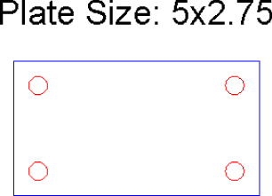
Figure 6.5 The completed plate created using the updated utility functions
Defining the New Get-DXF-Value and Set-DXF-Value Utility Functions
Modifying objects using entity data lists might seem confusing to you—and you aren't alone if you feel that way. Entity data lists can even be confusing to some of the most veteran programmers at times, as they are not used all the time. Most veteran programmers create utility functions that simplify the work.
In my personal utility library, I have two functions named Get-DXF-Value and Set-DXF-Values that can be used to manipulate entity data lists. The Get-DXF-Value function gets the value of a dotted pair based on a DXF group code in an entity data list, whereas Set-DXF-Values replaces a dotted pair or appends a new dotted pair in an entity data list. Set-DXF-Values can be used to construct an entity data list as well. The following steps explain how to define the Get-DXF-Value and Set-DXF-Values custom functions:
- Open the
utility.lspfile in Notepad on Windows or TextEdit on Mac OS, if it is not already open from the previous steps. - In the text editor area, position the cursor after the last expression in the file and press Enter twice. Then type the following:
; Returns the value of the specified DXF group code (defun Get-DXF-Value (entityName DXFcode / ) (cdr (assoc DXFcode (entget entityName))) ) ; Sets the value of the specified DXF group code for the supplied entity name (defun Set-DXF-Value (entityName DXFcode newValue / entityData newPropList oldPropList) ; Get the entity data list for the object (setq entityData (entget entityName)) ; Create the dotted pair for the new property value (setq newPropList (cons DXFcode newValue)) (if (setq oldPropList (assoc DXFcode entityData)) (setq entityData (subst newPropList oldPropList entityData)) (setq entityData (append entityData (list newPropList))) ) ; Update the object's entity data list (entmod entityData) ; Refresh the object onscreen (entupd entityName) ; Return the new entity data list entityData ) - Click File Save.
Moving Objects to Correct Layers
Not everyone will agree on the naming conventions, plot styles, and other various aspects of layers, but there are a few things drafters can agree on when it comes to layers—that objects should do the following:
- Inherit their properties, for the most part, from the layers in which they are placed
- Only be placed on layer 0 when creating blocks
While I would like to think all the drawings I've created are perfect, I know that rush deadlines or other distractions may have affected quality. Maybe the objects were placed on the wrong layer or maybe it wasn't my fault and standards simply changed during the course of a project. With AutoLISP, you can identify potential problems in a drawing to let the user know about them so they can be fixed, or you can make the changes using AutoLISP.
In these steps, you create a custom function named furnlayers that is used to identify objects by type and value to ensure they are placed on the correct layer. This is achieved using selection sets and entity data lists, along with looping and conditional statements.
- Create a new LSP file named
furntools.lspwith Notepad on Windows or TextEdit on Mac OS. - In the text editor area of the
furntools.lspfile, type the following:; Moves objects to the correct layers based on a set of established rules (defun c:FurnLayers ( / ssFurn cnt entityName entityData entityType) ; Request the user to select objects (setq ssFurn (ssget)) ; Proceed if ssFurn is not nil (if ssFurn (progn ; Set up the default counter (setq cnt 0) ; Step through each block in the selection set (while (> (sslength ssFurn) cnt) ; Get the entity name and entity data of the object (setq entityName (ssname ssFurn cnt) entityData (entget entityName) entityType (strcase (Get-DXF-Value entityName 0))) ; Conditional statement used to branch based on object type (cond ; If object is a block, continue ((= entityType "INSERT") (cond ; If the block name starts with RD or CD, ; then place it on the surfaces layer ((wcmatch (strcase (Get-DXF-Value entityName 2)) "RD*,CD*") (Set-DXF-Value entityName 8 "surfaces") ) ; If the block name starts with PNL, PE, and PX, ; then place it on the panels layer ((wcmatch (strcase (Get-DXF-Value entityName 2)) "PNL*,PE*,PX*") (Set-DXF-Value entityName 8 "panels") ) ; If the block name starts with SF, ; then place it on the panels layer ((wcmatch (strcase (Get-DXF-Value entityName 2)) "SF*") (Set-DXF-Value entityName 8 "storage") ) ) ) ; If object is a dimension, continue ((= entityType "DIMENSION") ; Place the dimension on the dimensions layer (Set-DXF-Value entityName 8 "dimensions") ) ) ; Increment the counter by 1 (setq cnt (1+ cnt)) ) ) ) (princ) )
Creating a Basic Block Attribute Extraction Program
The designs you create take time and, based on the industry you are in, are often what is used to earn income for your company or even save money. Based on the types of objects in a drawing, you can step through a drawing and get attribute information from blocks or even geometric values such as lengths and radii of circles. You can use the objects in a drawing to estimate the potential cost of a project or even provide information to manufacturing.
In these steps, you create a custom function named furnbom that is used to get the values of two attributes (part and label) attached to a block. The attribute values are added to a list and then sorted using the acad_strlsort function. Once sorted, the list is then parsed and quantified into a new list, which is used to create the a BOM table made up of lines and text.
- Open the
furntools.lspfile with Notepad on Windows or TextEdit on Mac OS, if it is not already open. - In the text editor area of the
furntools.lspfile, type the following:; extAttsFurnBOM - Extracts, sorts, and quanitifies the attribute information (defun extAttsFurnBOM (ssFurn / cnt preVal part label furnList) ; Set up the default counter (setq cnt 0) ; Step through each block in the selection set (while (> (sslength ssFurn) cnt) ; Get the entity name and entity data of the block (setq entityName (entnext (ssname ssFurn cnt))) (setq entityData (entget entityName)) ; Step through the objects that appear after ; the block reference, looking for attributes (while (/= (cdr (assoc 0 entityData)) "SEQEND") ; Check to see which if the attribute tag is PART or TAG (cond ((= (strcase (Get-DXF-Value entityName 2)) "PART") (setq part (Get-DXF-Value entityName 1)) ) ((= (strcase (Get-DXF-Value entityName 2)) "LABEL") (setq label (Get-DXF-Value entityName 1)) ) ) ; Get the next entity (attribute or sequence end) (setq entityName (entnext entityName)) (setq entityData (entget entityName)) ) ; Add the part and label values to the list (setq furnList (append furnList (list (strcat label " " part)) )) ; Increment the counter by 1 (setq cnt (1+ cnt)) ) ; Sort the list of parts and labels (setq furnListSorted (acad_strlsort furnList)) ; Reset and set variables that will be used in the looping statement (setq cnt 0 furnList nil preVal nil) ; Quantify the list of parts and labels ; Step through each value in the sorted list (foreach val furnListSorted ; Check to see if the previous value is the same as the current value (if (or (= preVal val)(= preVal nil)) (progn ; Increment the counter by 1 (setq cnt (1+ cnt)) ) ; Values weren't the same, so record the quanity (progn ; Add the quanity and the value (part/label) to the final list (setq furnList (append furnList (list (list (itoa cnt) (substr preVal 1 (vl-string-search " " preVal)) (substr preVal (+ (vl-string-search " " preVal) 2))) ))) ; Reset the counter (setq cnt 1) ) ) ; keep the previous value for comparison (setq preVal val) ) ; Add the quanity and the value (part/label) to the final list (setq furnList (append furnList (list (list (itoa cnt) (substr preVal 1 (vl-string-search " " preVal)) (substr preVal (+ (vl-string-search " " preVal) 2))) ))) ; Return the quantified and control character-delimited " " furnList ) ; Create the bill of materials table/grid (defun tableFurnBOM (qtyList insPt / colWidths tableWidth rowHeight tableHeight headers textHeight col insText item insTextCol bottomRow) ; Define the sizes of the table and grid (setq colWidths (list 0 15 45 50) tableWidth 0 row 1 rowHeight 4 tableHeight 0 textHeight (- rowHeight 1)) ; Get the table width by adding all column widths (foreach colWidth colWidths (setq tableWidth (+ colWidth tableWidth)) ) ; Define the standard table headers (setq headers (list "QTY" "LABELS" "PARTS")) ; Create the top of the table (entmake (list (cons 0 "LINE") (cons 10 insPt) (cons 11 (polar insPt 0 tableWidth)))) ; Get the bottom of the header row (setq bottomRow (polar insPt (* -1 (/ PI 2)) rowHeight)) ; Add headers to the table (rowValuesFurnBOM headers bottomRow colWidths) ;; (setq tableHeight (+ tableHeight rowHeight)) ; Step through each item in the list (foreach item qtyList (setq row (1+ row)) (setq bottomRow (polar insPt (* -1 (/ PI 2)) (* row rowHeight))) (rowValuesFurnBOM item bottomRow colWidths) ) ; Create the vertical lines for each column (setq colWidthTotal 0) (foreach colWidth colWidths ; Calculate the placement of each vertical line (left to right) (setq colWidthTotal (+ colWidth colWidthTotal)) (setq colBasePt (polar insPt 0 colWidthTotal)) ; Draw the vertical line (entmake (list (cons 0 "LINE") (cons 10 colBasePt) (cons 11 (polar colBasePt (* -1 (/ PI 2)) (distance insPt bottomRow))))) ) ) (defun rowValuesFurnBOM (itemsList bottomRow colWidths / tableWidth) ; Calculate the insertion point for the header text (setq rowText (list (+ 0.5 (nth 0 bottomRow)) (+ 0.5 (nth 1 bottomRow)) (nth 2 bottomRow)) tableWidth 0 ) ; Get the table width by adding all column widths (foreach colWidth colWidths (setq tableWidth (+ colWidth tableWidth)) ) ; Lay out the text in each row (setq col 0 colWidthTotal 0) (foreach item itemsList ; Calculate the placement of each text object (left to right) (setq colWidthTotal (+ (nth col colWidths) colWidthTotal)) (setq insTextCol (polar rowText 0 colWidthTotal)) ; Draw the single-line text object (entmake (list (cons 0 "TEXT") (cons 100 "AcDbEntity") (cons 100 "AcDbText") (cons 10 insTextCol) (cons 40 textHeight) (cons 1 item) (cons 50 0.0) (cons 7 "Standard") (cons 11 insTextCol) (cons 100 "AcDbText"))) ; Create the top of the table (entmake (list (cons 0 "LINE") (cons 10 bottomRow) (cons 11 (polar bottomRow 0 tableWidth)))) ; Increment the counter (setq col (1+ col)) ) ) ; Extracts, aggregates, and counts attributes from the furniture blocks (defun c:FurnBOM ( / ssFurn eaList) ; Get the blocks to extract (setq ssFurn (ssget '((0 . "INSERT")))) ; Use the extAttsFurnBOM to extract and quantify the attributes in the blocks ; If ssFurn is not nil proceed (if ssFurn (progn ; Extract and quantify the parts in the drawing (setq eaList (extAttsFurnBOM ssFurn)) ; Create the layer named BOM or set it as current (createlayer "BOM" 8) ; Prompt the user for the point to create the BOM (setq insPt (getpoint " Specify upper-left corner of BOM: ")) ; Start the function that creates the table grid (tableFurnBOM eaList insPt) ) ) (princ) ) - Click File Save.
Using the Functions in the furntools.lsp File
The functions you added to furntools.lsp leverage some of those defined in utility.lsp. These functions allow you to change the layers of objects in a drawing and extract information from the objects in a drawing as well. More specifically, they let you work with blocks that represent an office furniture layout.
Although you might be working in a civil engineering– or mechanical design–related field, these concepts can and do apply to the work you do—just in different ways. Instead of extracting information from a furniture block, you could get and set information in a title block, a callout, or even an elevation marker. Making sure a hatch is placed on the correct layers, along with dimensions, can improve the quality of output for the designs your company creates.
The following steps explain how to use the furnlayers function that is in the furntools.lsp file:
- Open
Ch06_Office_Layout.dwg. Figure 6.6 shows the office layout that is in the drawing.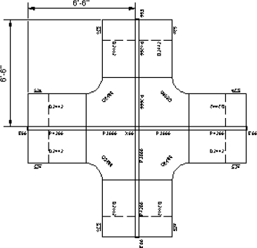
Figure 6.6 Office furniture layout
- Start the
apploadcommand. Load the LSP filesfurntools.lspandutility.lsp. If the File Loading - Security Concerns message box is displayed, click Load. - At the Command prompt, type
furnlayersand press Enter. - At the
Select objects:prompt, select all the objects in the drawing and press Enter.The objects in the drawing are placed on the correct layers. Earlier the objects were placed on layer 0 and had a color of white (or black) based on the background color of the drawing area.
The following steps explain how to use the furnbom function that is in the furntools.lsp file:
- Open the
Ch06_Office_Layout.dwgif it is not open from the previous steps. - Load the
furntools.lspandutility.lspfiles if you opened the drawing in step 1. - At the Command prompt, type
furnbomand press Enter. - At the
Select objects:prompt, select all the objects in the drawing. Don't press Enter yet.Notice that the dimension objects aren't highlighted. This is because the
ssgetfunction is only allowing block references (insertobject types) to be selected as a result of the filter being applied. - Press Enter to end the object selection.
- At the
Specify upper-left corner of BOM:prompt, specify a point to the right of the furniture layout in the drawing.The BOM that represents the furniture blocks is placed in a table grid, as shown in Figure 6.7.
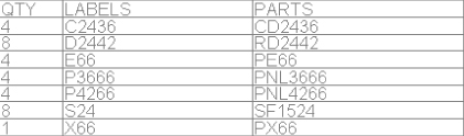
Figure 6.7 Bill of materials generated from the office furniture layout