
Chapter 13
Implementing Dialog Boxes (Windows only)
The goal of any program should be to make end users be productive and feel empowered without getting in their way. Your decisions about the number of options and how they are presented can make or break a custom function. Include too many, and the user becomes frustrated while responding to prompts about options that aren't used frequently; too few, and the usefulness of the custom function suffers. Dialog boxes allow users to see values that might normally be hidden behind a set of prompts and provide input for only those options they are interested in changing. A dialog box can also be used to combine multiple functions into a single, easy-to-use interface.
For example, consider the difference between the insert command, which displays the Insert dialog box, and the -insert command, which displays a series of options at the Command prompt. The insert command allows you to explode a block upon insert and use geographical data without affecting the prompt sequence or functionality of the -insert command. In this chapter, you will learn to implement dialog boxes for use with AutoLISP® programs.
What Is Dialog Control Language?
Dialog Control Language (DCL) is the technology used to lay out and design dialog boxes that can be used with AutoLISP programs. Support for DCL was originally added to Autodesk® AutoCAD® R11 and has remained essentially unchanged through AutoCAD 2015. Dialog boxes are defined and stored in ASCII text files with a .dcl extension. Once a DCL file has been created, AutoLISP can then load and display the dialog contained in the DCL file. After the dialog is displayed, AutoLISP is used to control what happens when the user clicks or otherwise manipulates the controls in the dialog box.
A DCL file can contain multiple dialog-box definitions. Each dialog box and control is defined through the use of a tile. The appearance of a tile is affected by what are known as attributes—think of attributes as the properties of a drawing object.
With the exception of the tile that defines the dialog box (the dialog tile), tiles typically start with a colon followed by the name of the tile type you want to place on the dialog box. The dialog tile must start with a user-defined name that is unique in the DCL file; this name is used to display the dialog box in the AutoCAD drawing environment. A pair of curly brackets that contain the attributes of the tile typically follows the name or type of a tile. Each attribute must end with a semicolon.
In addition to attributes, some tiles contain nested tiles, which are placed within a tile's curly brackets. Some tile names aren't followed by a pair of curly brackets because they don't support attributes; these tiles are known as subassemblies. Subassemblies help you implement standardized tile groupings. The OK and Cancel button tiles used in most dialogs created with DCL are examples of subassemblies.
Listing 13.1 shows an example of a dialog box definition that could be used as part of an alternative to the message box that is automatically displayed with the alert function. Remember, the alert function displays a message box with an OK button only.
Figure 13.1 shows what the alternative message box looks like when loaded into the AutoCAD drawing environment. A DCL file can also contain comments, which are prefixed with // or located between the character groupings /* and */. Both comment styles are shown in Listing 13.1.
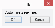
Figure 13.1 Alternative message box defined with DCL
Defining and Laying Out a Dialog Box
DCL files can be created and edited using Notepad, the Visual LISP® Editor, or whichever editor you are using for LSP files. Although you can use Notepad, the Visual LISP Editor offers a few advantages over Notepad for working with DCL files. It supports color syntax as it does with LSP files, but it also has a built-in DCL preview feature. Without the Visual LISP Editor's DCL preview feature, you must write an AutoLISP program that will at least load a DCL file and display a dialog box in the AutoCAD drawing environment to see the final appearance of a dialog box.
Defining a Dialog
Each dialog box you define must contain a dialog tile. The attributes of a dialog tile are used to define the dialog's label (more commonly referred to as the title or caption), add a programmatic name known as a key, and set the tile that should have initial focus. The following shows the basic syntax of the dialog tile:
dialog_name : dialog {
   [attributes]
   [tiles]
}
Here are its arguments:
dialog_nameThedialog_nameargument represents the name used to reference a dialog box within a DCL file. A DCL file can contain more than onedialogtile, but each must have a unique name. The same name can be used in different DCL files without any problems.AttributesTheattributesargument is a list of optional attributes that describe thedialogtile. An attribute consists of a name and value, separated by an equals sign, and ends with a semicolon. For example,label = "Title";specifies the use of the attribute namedlabeland that it should be assigned the value ofTitle. See Table 13.1 for a list of the attributes that thedialogtile supports.TilesThetilesargument is a list of optional tiles that define the controls that you want to display in the dialog box. For information on the tiles that are available, see the “Adding Tiles” and “Grouping, Aligning, and Laying Out Tiles” sections later in this chapter.
Table 13.1 lists and describes the attributes that can be applied to the dialog tile.
Table 13.1 Common attributes used with the dialog tile
| Attribute | Description |
label |
The title that is assigned to the dialog box. |
value |
Alternative to the title attribute. This attribute can be set only with the set_tile function. I discuss the set_tile function later in this chapter, in the “Setting the Default Value of an Interactive Tile” section. |
initial_focus |
The key assigned to the tile in the dialog tile that should have focus by default when the dialog box is displayed. |
An example of a dialog tile was shown earlier in this chapter; see Listing 13.1 and Figure 13.1.
Adding Tiles
A dialog box can contain a variety of tiles—commonly referred to as controls—that can be used to get input from the user. The tiles that are available for placement in a dialog box are common to many Windows dialog boxes. The following shows the basic syntax of a tile:
: tile_name {
   [attributes]
}
Here are its arguments:
tile_nameThetile_nameargument represents the name of the tile type to place in the dialog box. See Table 13.2 for the tile names that are supported.AttributesTheattributesargument is a list of optional attributes that describe the tile. An attribute consists of a name and value, separated by an equals sign, and ends with a semicolon. For example,label = "Control1";specifies the use of the attribute namedlabeland that it should be assigned the value ofControl1. See Table 13.3 for a list of the common attributes that tiles support.
Table 13.2 lists and describes the interactive tiles that can be added to a dialog tile for getting input from the user when a dialog box is displayed.
Table 13.2 Interactive tiles available with the dialog tile
| Tile name | Description |
button |
Push or command button that, when clicked, executes a function. |
edit_box |
Free-form text box in which the user can enter an alphanumeric value. |
image |
Container that displays a slide image. The slide image can be a stand-alone SLB file or one from a compiled slide library SLD file. |
image_button |
Graphical button that displays a slide image that, when clicked, executes a function. |
list_box |
List box that contains a set of predefined items from which the user can select one or more items. |
popup_list |
Drop-down list that contains a set of predefined items from which the user can choose a single item. |
radio_button |
Option button that allows for a single choice among multiple option buttons. |
slider |
Scroll bar–like control that allows the user to specify a value within a specific range. |
text |
Label that displays information to the user or identifies the intention of a control. |
toggle |
Check-box button that allows for multiple choices. |
Table 13.3 lists and describes some of the most commonly used attributes to control the behavior of tiles other than a dialog tile.
Table 13.3 Common attributes used with control tiles
| Attribute | Supported Tile(s) | Description |
action |
All interactive tiles | Function to be executed when the tile is clicked. |
allow_accept |
edit_box, image_button, and list_box |
Activates the button that is specified with the is_default attribute. |
edit_limit |
edit_box |
Maximum number of characters that can be entered into the text box. |
is_cancel |
button |
Indicates that the function associated with the button tile's action attribute should be executed when Esc is pressed. |
is _default |
button |
Indicates that the function associated with the button tile's action attribute should be executed when Enter is pressed. |
is_enabled |
All interactive control tiles | Indicates that the tile is enabled or disabled. |
key |
All interactive control tiles | Unique name used to programmatically reference the tile. |
label |
button, edit_box, list_box, popup_list, radio_button, text, and toggle |
Label that describes the intention of the tile and is displayed adjacent to the tile. |
list |
list_box and popup_list |
Items that are displayed and selectable by the user in the list. The character sequence
is used to separate each item in the list. |
multiple_select |
list_box |
Indicates that the list supports multiple selections. |
value |
text_box and interactive tiles except button and image_button tiles |
Current value of a tile. |
To see what values an attribute supports, search on the keywords “programmable dialog box reference” in the AutoCAD Help system. Search on the keywords “synopsis predefined attributes” in the AutoCAD Help system to see the other attributes that are available.
Listing 13.2 shows an example of a dialog box that contains a popup_list, two radio_button tiles, and a button tile. Figure 13.2 shows what the dialog box would look like if displayed in the AutoCAD drawing environment using AutoLISP.
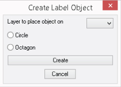
Figure 13.2 Example dialog box titled Create Label Object
In addition to the tiles listed in Table 13.2, DCL makes use of tile subassemblies. Tile subassemblies are used to provide common arrangements of exit buttons. Table 13.4 shows several of the available tile subassemblies that can be used in a dialog tile. You can view the names of the subassemblies in the base.dcl file located in the AutoCAD Support folder. A subassembly ends with a semicolon, as shown in Listings 13.1 and 13.2. You can't change the attribute values of a subassembly provided by AutoCAD, but you can re-create a subassembly with different attribute values in your own DCL files. Use the syntax found in the base.dcl file as the basis for your new subassembly code. The base.dcl file can be found in the AutoCAD support-file search path by entering (findfile "base.dcl") at the Command prompt.
Table 13.4 Tile subassemblies
| Tile Subassembly | Description |
cancel_button |
Cancel only button |
ok_button |
OK only button |
ok_cancel |
OK and Cancel buttons |
ok_cancel_help_ |
OK, Cancel, and Help buttons |
Grouping, Aligning, and Laying Out Tiles
Tiles are stacked vertically in a dialog box by default, unless you use what are called cluster tiles. Cluster tiles are used to group and align tiles in rows and columns. Tiles also support several attributes that help you control their size and alignment in a dialog box. In addition to cluster tiles and attributes, spacer tiles can be used to control the size and alignment of tiles. A spacer tile allows for the insertion of empty space between tiles in a dialog box.
Grouping Tiles into Clusters
Grouping tiles into a cluster allows you to better control how they are aligned or organized in the dialog box, in addition to controlling which radio_button tiles are related to each other. A cluster tile must be used to restrict the choice of multiple radio_button tiles in a dialog box so only one option button can be selected at a time. Tiles can be grouped into columns and rows with or without a visual grouping box. Table 13.5 lists and describes the cluster tiles that can be used to group tiles.
Table 13.5 Cluster tiles
| Tile Name | Description |
boxed_column |
Groups tiles into a column and draws a box with a label around the tiles. |
boxed_radio_column |
Groups related radio_button tiles into a column and draws a box with a label around the tiles; tiles are treated as exclusive to each other. |
boxed_radio_row |
Groups related radio_button tiles into a row and draws a box with a label around the tiles; tiles are treated as exclusive to each other. |
boxed_row |
Groups tiles into a row and draws a box with a label around the tiles. |
column |
Groups tiles into a column; no grouping box is drawn around the tiles. |
radio_column |
Groups related radio_button tiles into a column; tiles are treated as exclusive to each other. No grouping box is drawn around the tiles. |
radio_row |
Groups related radio_button tiles into a row; tiles are treated as exclusive to each other. No grouping box is drawn around the tiles. |
row |
Groups tiles into a row; no grouping box is drawn around the tiles. |
Listing 13.3 shows a revised version of the DCL syntax shown in Listing 13.2. The revised syntax uses the boxed_radio_column and row cluster tiles to group tiles. Figure 13.3 shows what the dialog box would look like if displayed in the AutoCAD drawing environment using AutoLISP.
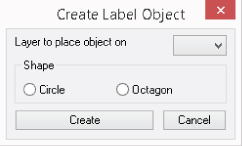
Figure 13.3 Grouping related tiles in the Create Label Object dialog box
Aligning and Sizing Tiles
When a dialog box is displayed, tiles have a default alignment and size assigned to them. In most cases, a tile's size is based on the label text that it is assigned, or the width of the dialog box or cluster tile that it is placed within. Table 13.6 describes the tile attributes that can be used to control the alignment and size of the tiles in a dialog tile.
Table 13.6 Attributes used with aligning and sizing tiles
| Attribute | Supported Tile(s) | Description |
alignment |
All tiles | Horizontal or vertical alignment of a tile |
children_alignment |
column, row, boxed_row, boxed_column, boxed_radio_column, boxed_radio_row, radio_column, and radio_row |
Overrides the horizontal or vertical alignment for all tiles contained in a cluster tile |
children_fixed_height |
column, row, boxed_row, boxed_column, boxed_radio_column, boxed_radio_row, radio_column, and radio_row |
Overrides the fixed height for all tiles contained in a cluster tile |
children_fixed_width |
column, row, boxed_row, boxed_column, boxed_radio_column, boxed_radio_row, radio_column, and radio_row |
Overrides the fixed width for all tiles contained in a cluster tile |
edit_width |
edit_box and popup_list |
Width of the input field, not the tile |
fixed_height |
All tiles | Absolute height of a tile |
fixed_width |
All tiles | Absolute width of a tile |
height |
All tiles | Minimum height of a tile; might increase when the dialog box is displayed |
width |
All tiles | Minimum width of a tile; might increase when the dialog box is displayed |
To see which values an attribute supports, search on the keywords “programmable dialog box reference” in the AutoCAD Help system.
In addition or as an alternative to using tile attributes, spacer tiles can be used to increase the space between tiles. Table 13.7 lists and describes the spacer tiles that can be used to align tiles and control tile size.
Table 13.7 Spacer tiles
| Tile Name | Description |
spacer |
Inserts a gap of the specified size in the horizontal or vertical direction; the direction that the gap is created in is defined by how the tile is clustered with other tiles. |
spacer_0 |
Inserts a gap that restricts the distribution or automatic resizing of tiles to the left or above the spacer tile. |
spacer_1 |
Inserts a gap of one unit wide by one unit high. |
Listing 13.4 shows a revised version of the DCL syntax shown in Listing 13.3. The revised syntax uses the edit_width attribute to size the popup_list tile, the fixed_width and alignment attributes on the row tile, the width attribute for the button tile, and a spacer tile to control the alignment and sizing of the tiles in the dialog box. Figure 13.4 shows what the dialog box would look like if displayed in the AutoCAD drawing environment using AutoLISP.
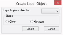
Figure 13.4 Setting the alignment and sizes of tiles
Creating and Previewing a Dialog in a DCL File
You can create a DCL file with Notepad or the Visual LISP Editor; you follow the same process you use to create a LSP file. The only difference is that you specify a file extension of .dcl instead of .lsp. Once you create a DCL file, you can add a dialog box definition to the file. To see what the dialog box looks like, you must load the DCL file in the AutoCAD drawing environment and display it. There are two approaches available for viewing a DCL file. The first is to create an AutoLISP program that loads and displays the file; the other involves using the Visual LISP Editor. (The second approach eliminates the need to write any code.) I discuss how to load a DCL file and display a dialog box in the next section.
The Visual LISP Editor makes it easy to create, modify, and preview a DCL file. When a DCL file is open and in the current window of the editor, you can click Tools ![]() Interface Tools
Interface Tools ![]() Preview in DCL Editor to preview the dialog box. A dialog box allows you to specify which dialog in the DCL file to preview. The Visual LISP Editor sends some AutoLISP code to the AutoCAD Command prompt and displays the dialog box. Click Cancel or another tile to close the dialog box and return to the Visual LISP Editor.
Preview in DCL Editor to preview the dialog box. A dialog box allows you to specify which dialog in the DCL file to preview. The Visual LISP Editor sends some AutoLISP code to the AutoCAD Command prompt and displays the dialog box. Click Cancel or another tile to close the dialog box and return to the Visual LISP Editor.
In this exercise, you will create a DCL file based on the dialog box defined in Listing 13.4 and then preview it using the Visual LISP Editor:
- In AutoCAD, click the Manage tab
 Applications panel Visual LISP Editor.
 - In the Visual LISP Editor, click File New File.
- Click File Save As.
- In the Save-as dialog box, browse to the
MyCustomFilesfolder within theDocuments(orMy Documents) folder, or the location you are using to store DCL files. - In the File Name text box, type
ex_createLabelObject. - Click the Save As Type drop-down list and choose DCL Source Files.
- Click Save.
- In the text editor window, type the following:
/* Create label object */ ex_createLabelObject : dialog { label = "Create Label Object"; key = "dlg_layer"; : popup_list { // Drop-down list edit_width = 10; key = "list_layers"; label = "Layer to place object on"; } : boxed_radio_row { label = "Shape"; : radio_button { // Circle key = "opt_circle"; label = "Circle"; } : radio_button { // Octagon key = "opt_octagon"; label = "Octagon"; } } : row { fixed_width = true; alignment = right; : button { // Create object button key = "btn_create_object"; action = "create_object"; label = "Create"; is_default = "true"; width = 12; } : spacer { width = 1; } cancel_button; } } - Click File Save.
- Click Tools Interface Tools Preview DCL In Editor.
- In the Enter The Dialog Name dialog box, click OK. That dialog box lists all the dialog-box definitions in the DCL file that is open in the editor.
- Review the dialog box and click any control to return to the Visual LISP Editor.
The dialog box you create should look like the one shown earlier, in Figure 13.4.
Loading and Displaying a Dialog Box
The Visual LISP Editor makes it easy to preview a dialog box, but it doesn't allow you to interact with the tiles on the dialog box. A DCL file must be loaded and displayed with AutoLISP to enable user interaction. When a dialog box is being loaded, you can set the initial values of each tile and specify the enabled state of each tile. If your dialog box contains any list_box, popup_list, image, or image_button tiles, you might have to perform some initialization tasks for these tiles. (I cover those tasks in the “Initializing Tiles” section later in this chapter.)
Loading and Unloading a DCL File
A DCL file must be loaded into the AutoCAD drawing environment before you can display one of the dialog-box definitions in the file. The load_dialog function loads a DCL file and returns a random integer value that represents a DCL file ID. A positive DCL file ID value indicates that the DCL file was located in the AutoCAD support-file search paths specified in the Options dialog box and was successfully loaded; a negative value notifies you that the DCL file wasn't located and loaded.
The following shows the syntax of the load_dialog function:
(load_dialog dcl_filename)The dcl_filename argument that the load_dialog function expects is a string that represents the path to and the filename of the DCL file you want to load. I recommend placing DCL files in the AutoCAD support-file search paths. When you do so, only the filename needs to be specified, making it easier to move the files on your network if needed.
Here is an example that loads a DCL file named ex_createLabelObject.dcl with the load_dialog function and the return of the DCL file ID, in this instance a value of 101. You should always store the DCL file ID in a variable so that you can display and unload a dialog box defined in the DCL file. The DCL file was created as part of the exercise in the “Creating and Previewing a Dialog in a DCL File” section earlier in this chapter.
(setq id (load_dialog "ex_createLabelObject.dcl"))
101
The unload_dialog function unloads a dialog box definition from memory; the particular dialog is identified by the DCL file ID that was returned by the load_dialog function. The DCL file ID changes each time the DCL file is loaded, and the value returned should be stored in a variable until the dialog box is no longer needed in the current drawing session. A dialog box can be loaded more than once; each time a dialog box is loaded, a new instance of the dialog box is stored in memory until it is unloaded. The following shows the syntax of the unload_dialog function:
(unload_dialog dcl_file_id)The dcl_file_id argument that the unload_dialog function expects is the same value that was returned by the load_dialog function. The unload_dialog function always returns a value of nil, and that value has no significant meaning; successfully or unsuccessfully unloading the dialog box results in the same value of nil. Here is an example of the unload_dialog function:
(unload_dialog id)
nil
Displaying a Dialog
After a DCL file has been loaded, an instance of a dialog box contained in the loaded DCL file can be created and displayed with the new_dialog function. The new_dialog function is also used to specify a default action for all interactive tiles that don't have an action assigned to them, and the onscreen display location. The new_dialog function returns T if the dialog box was successfully created, or it returns nil if the dialog box couldn't be created.
The following shows the syntax of the new_dialog function:
(new_dialog dialog_name dcl_file_id [action [point]])Here are its arguments:
dialog_nameThedialog_nameargument is a case-sensitive string that specifies the unique name of the dialog to create an instance of from the DCL file specified by thedcl_file_idargument. The value must exactly match the name applied to thedialogtile and is case sensitive.dcl_file_idThedcl_file_idargument that thenew_dialogfunction expects is the value that was returned by theload_dialogfunction.ActionTheactionargument is an optional string that represents an AutoLISP expression. This expression is applied to theactionattribute of all interactive tiles that aren't assigned an action as part of the DCL file; the function is executed when the tile is clicked. Provide""when you want to specify thepointargument but no default action.PointThepointargument is an optional 2D point list that represents the onscreen location of the dialog box's upper-left corner. The dialog box is centered by default and can be specified with a value of ″(-1 -1). The upper-left corner of the screen is 0,0.
Once an instance of a dialog box has been created with the new_dialog function, the start_dialog function must eventually be called. The start_dialog function informs AutoCAD that the dialog box is ready for user interaction. Before start_dialog is executed, you should make sure that all initial default values and enabled states have been specified. The next section explains how to set the default values for and specify the enabled state of tiles, as well as initialize lists and images.
The start_dialog function doesn't accept any arguments and returns a status value based on how the user exited the dialog box. A status value of 1 generally means the user clicked OK or a similar button, whereas a value of 0 indicates the user clicked Cancel or the Close button. The status value returned by a tile is determined by the value passed to the done_dialog function. I cover the done_dialog function later in this chapter, in the “Terminating or Closing a Dialog Box” section. You don't need to worry about executing the done_dialog function if you use one of the tile subassemblies that contains the OK or Cancel button mentioned earlier, in the “Adding Tiles” section.
The following example code shows how to load and unload a DCL file, and then create and display a dialog box. ex_createLabelObject.dcl is the name of the DCL file that will be loaded. The dialog box definition name is ex_createLabelObject. Although in this example the DCL file and dialog name are the same, they don't need to be. I recommend having one dialog box per DCL file and using the same name, but that is just a personal preference.
; Define a function named createlabelobject
(defun c:createlabelobject (/ dialog_name id)
  (setq dialog_name "ex_createLabelObject")
  ; Load the DCL file named ex_createLabelObject.dcl
  (setq id (load_dialog (strcat dialog_name ".dcl")))
  ; Create a new instance of the dialog named ex_createLabelObject
  ; in the center of the screen
  (new_dialog dialog_name id "" '(-1 -1))
  ; Perform additional tasks here
  ; 1. Set default values for tiles here with the set_tile function
  ; 2. Set up lists and images here
  ; 3. Assign actions here for tiles with the action_tile function
  ; 4. Get information about a tile with get_tile as part of the
  ;    action assigned with action_tile
  ; 5. Terminate the dialog box with the done_dialog function as
  ;    part of the action assigned with action_tile
  ; Display the dialog box and get the exit status
  (setq status (start_dialog))
  ; Unload the DCL file from memory
  (unload_dialog id)
  ; Display a custom message based on the exit status of the dialog
  (if (= status 1)
    (alert "User clicked Create.")
    (alert "User clicked Cancel.")
  )
 (princ)
)
Initializing Tiles
You can manipulate the interactive tiles of a dialog tile in a DCL file once you create an instance of a dialog box in memory by using the new_dialog function. You use the value of the key attribute to reference a tile of a dialog box. Once you have a tile's key, you can set the default value of a tile, set the tile's enabled state, populate items in the list of a list_box or popup_list tile, or assign a slide to an image or image_button tile.
Setting the Default Value of an Interactive Tile
When you use a dialog box, have you ever noticed that it often remembers the previously entered values or that values change based on the controls you interact with? You can assign a default value to a tile by using the value attribute in a DCL file or change the default value before a dialog box is displayed by using the set_tile function.
I recommend setting the default value of a tile using the set_tile function, considering it is good practice to restore previously entered values each time the dialog box is redisplayed. The set_tile function can also be used to change the value of a tile when the user interacts with a tile while the dialog box is displayed. I discuss how to handle user interaction with tiles in the “Interacting with and Responding to a User” section later in this chapter.
The following shows the syntax of the set_tile function:
(set_tile key val)Here are its arguments:
keyThekeyargument is a string that specifies the value assigned to thekeyattribute of the tile you want to modify.ValThevalargument is the string value you want to assign to the tile. An alphanumeric string can be assigned to anedit_boxtile, whereas an integer formatted as a string can be assigned to alist_box,popup_list,toggle,radio_button, orslidertile. The first item in the list of alist_boxorpopup_listtile is 0, the second is 1, and so on.
The following code shows how to set a value of 1, which means true, to a tile with the key of opt_circle using the set_tile function. The key opt_circle refers to the Circle radio_button tile of the ex_createLabelObject dialog definition you created in the “Creating and Previewing a Dialog in a DCL File” section.
(set_tile "opt_circle" "1")Enabling and Disabling an Interactive Tile
The tiles of a dialog box are all enabled by default, meaning the user can click or enter text in any interactive tile of a dialog box. The is_enabled attribute of a tile controls the tile's default enabled state. When is_enabled is set to false, the user is unable to interact with the tile when the dialog box is displayed. The enabled state of a tile can be changed using the mode_tile function.
I recommend setting the enabled state of a tile using the mode_tile function and not the is_enabled attribute. The main reason for doing so is because the disabling of a tile is often based on the condition of other tiles or choices made by the user in the dialog box. I discuss how to handle user interaction with tiles in the “Interacting with and Responding to a User” section.
The following shows the syntax of the mode_tile function:
(mode_tile key mode)Here are its arguments:
keyThekeyargument is a string that specifies the value assigned to thekeyattribute of the tile you want to modify.ModeThemodeargument is an integer value that specifies the mode that should be applied to the tile. Table 13.8 lists the available modes that can be applied to a tile.Table 13.8 Modes available for use with the
mode_tilefunctionMode Description 0Enables an interactive tile 1Disables an interactive tile 2Sets focus to an interactive tile 3Selects the text in an edit_boxtile4Toggles highlighting for an imagetile
The following code shows how to disable and then enable a tile with the key of opt_circle using the mode_tile function. The key opt_circle refers to the Circle radio_button tile of the ex_createLabelObject dialog definition you created in the “Creating and Previewing a Dialog in a DCL File” section.
; Disables tile
(mode_tile "opt_circle" 1)
; Enables tile
(mode_tile "opt_circle" 0)Populating the Items of a list_box or popup_list Tile
The list_box and popup_list tiles allow the user to select one or more predefined values from a list. The items available in the list of the two tiles can be specified using the tile's list attribute or AutoLISP functions. The start_list function is used to assign, update, or replace the list of values applied to a list_box or popup_list tile. When a list can be modified, the start_list function returns the name of the list; otherwise the function returns nil, indicating the list isn't accessible for modification. Typically, a list isn't available for modification because you provided an incorrect key to the start_list function or the function was called before the execution of the new_dialog function.
The following shows the syntax of the start_list function:
(start_list key [mode [idx]])Here are its arguments:
keyThekeyargument is a string that specifies the value assigned to thekeyattribute of the tile you want to modify.ModeThemodeargument is an integer value that specifies how the list currently assigned to the tile can be modified. Table 13.9 describes each of the available modes.IdxTheidxargument is an integer value that specifies an item in the list. The item is used to indicate which item to change if the mode is set to 1; when the mode is set to 2, it indicates the starting item you want to begin appending new items to.
Table 13.9 describes the modification modes that can be used to edit a list.
Table 13.9 List-editing modes
| Mode | Description |
1 |
Next call to add_list replaces the item indicated by the idx argument. |
2 |
Next call to add_list appends a new item after the item indicated by the idx argument. If an index isn't provided, the new item is appended after the last item in the list. |
3 |
Items in the list are cleared and a new item is appended. |
After a tile key, mode, and index have been specified with the start_list function, you can change or add new items with the add_list function. The add_list function accepts a single argument of a string value. This value is the text that will be displayed in the list of the list_box or popup_list tile. If the value is successfully added to the list, the string passed to the add_list function is returned; otherwise, nil is returned, indicating the item wasn't added.
Once you have modified a list, use the end_list function. The end_list ends the modification of the list that was started with the start_list function. The end_list function returns a value of nil regardless of whether the list was successfully modified.
The following code shows how to replace and assign a list of two values to a popup_list tile with the key of list_layers. The list_layers key refers to the Layer To Place Object On popup_list tile of the ex_createLabelObject dialog definition you created in the “Creating and Previewing a Dialog in a DCL File” section.
; Clear and replace the list of the popup_list
(start_list "list_layers" 2)
; Add two items that represent the layers to allow
(add_list "A-Door")
(add_list "A-Window")
; End list modification
(end_list)Working with image and image_button Tiles
The image and image_button tiles allow you to display a slide in a frame or as a graphical button. Based on the image you want to display, you will need to use one of several AutoLISP functions to initialize the tile. In earlier AutoCAD releases, image_button tiles were used to display a preview of a block and then start an AutoLISP expression that would allow the insertion of the block. However, the relevance of the image and image_button tiles in a dialog box has diminished in recent releases with interfaces such as the ribbon and Tool Palettes window.
If you want to display a slide (SLD) file in a dialog definition with an image or image_button tile, you will want to explore the functions listed in Table 13.10. You can learn more about these functions in the AutoCAD Help system.
Table 13.10 AutoLISP functions used to work with image and image_button tiles
| Function Name | Description |
dimx_tile |
Returns the width of an image or image_button tile |
dimy_tile |
Returns the height of an image or image_button tile |
end_image |
Ends the modification of the current image set by the start_image function |
fill_image |
Draws a filled rectangle in the current image set by the start_image function |
slide_image |
Displays a slide (SLD) file or a slide in a slide library (SLB) file in the current image |
start_image |
Starts the modification of an image and sets it as the current image |
vector_image |
Draws a vector in the current image set by the start_image function |
Interacting with and Responding to a User
While a dialog box is displayed onscreen, the user is able to interact with the tiles that are enabled. As the user interacts with the tiles, the AutoLISP expressions assigned to the tile's action attribute are executed. The AutoLISP expressions can be used to get and set tile and attribute values, and to change the enabled state of a tile.
Specifying the Action of a Tile
An interactive tile can be assigned an AutoLISP expression that is to be executed when the tile is clicked or interacted with. You use the action attribute in a DCL file to assign an AutoLISP expression to a tile or the action_tile function. As part of the AutoLISP expression, you can get information about the tile that is being interacted with by using several predefined variables. Table 13.11 lists the predefined variables that can be referenced by the AutoLISP expression assigned to a tile's action attribute.
Table 13.11 Predefined variables that contain information about the current tile
| Variable Name | Description |
$data |
Custom information assigned to a tile with the client_data_tile function. |
$key |
Key name assigned to the tile. |
$reason |
Callback reason based on the interaction performed by the user. Possible values are 1, 2, 3, or 4. 1 indicates the user has clicked or pressed Enter to activate a tile, 2 means the user exited an edit_box tile, 3 indicates the value of a slider tile has changed, and 4 is returned when a list_box or image tile is double-clicked. |
$value |
Current value of the tile. |
$x |
Coordinate value of an image along its x-axis when an image_button tile is clicked. |
$y |
Coordinate value of an image along its y-axis when an image_button tile is clicked. |
I recommend setting a tile's action using the action_tile function to give you the flexibility to dynamically change the AutoLISP expression that is assigned while the user is interacting with the dialog box. For example, you might want to assign a different action to a button tile based on the radio_button tile that the user chooses.
The following shows the syntax of the action_tile function:
(action_tile key expr)Here are its arguments:
keyThekeyargument is a string that specifies the value assigned to thekeyattribute of the tile you want to modify.ExprTheexprargument is a string value that represents the AutoLISP expression that should be executed when the user interacts with the tile.
The following code shows how to assign the AutoLISP expression (alert (strcat "Tile key: " $key)) to the tile with the key of opt_circle using the action_tile function. The key opt_circle refers to the Circle radio_button tile of the ex_createLabelObject dialog definition you created in the “Creating and Previewing a Dialog in a DCL File” section.
(action_tile "opt_circle" "(alert (strcat "Tile key: " $key))")Getting Information about a Tile
When a user interacts with the tiles of a dialog box, you will commonly want to get the current value of one or all tiles before the dialog box is closed. The current value of the value attribute of a tile can be obtained using the get_tile function. If you want to get the value of an attribute other than value, you can use the get_attr function. The get_tile and get_attr functions return a string value.
The following shows the syntax of the get_tile and get_attr functions:
(get_tile key)
(get_attr key attr)
Here are their arguments:
keyThekeyargument is a string that specifies the value assigned to thekeyattribute of the tile to query.AttrTheattrargument is a string value that specifies the name of the attribute to query.
The following code shows how to get the current value of the tile with the key of opt_circle using the get_tile function, and get the items assigned to the list attribute of a popup_list tile with the key of list_layers. These tiles are part of the ex_createLabelObject dialog definition you created in the “Creating and Previewing a Dialog in a DCL File” section.
; Gets the current value of the tile
(get_tile "opt_circle")
"1"
; Gets the current value of the list attribute
(get_attr "list_layers" "list")
"A-Door
A-Window"
Terminating or Closing a Dialog Box
A dialog box must be terminated—or closed—when it is no longer needed and the end user wants to return to the drawing area. The done_dialog function is used to indicate that the dialog box can be terminated. You commonly add this function as the last part of the AutoLISP expression assigned to the action attribute of a button tile such as OK or Cancel that terminates a dialog box. Before done_dialog is executed, you want to make sure you get the value of any tiles or tile attribute values by using the get_tile or get_attr function.
The done_dialog function returns a 2D point list that represents the current placement of the dialog box onscreen. You can store this value as part of the Windows Registry, and then, to restore the location the next time the dialog box is displayed, pass the 2D point list to the new_dialog function.
The following shows the syntax of the done_dialog function:
(done_dialog [status])The status argument is an integer value that will be returned by the start_dialog function. Typically, 0 indicates that the user clicked Cancel or the dialog box was canceled, whereas 1 indicates that the user clicked OK or an equivalent tile. A value greater than 2 can be passed to the status argument.
The following code shows how to assign a custom action to the OK and Cancel buttons of a dialog box. The alert function is called before done_dialog to simply demonstrate that more than one AutoLISP function can be called from a tile's action.
; Assign an action to the OK button
(action_tile "accept" "(alert "OK clicked.")(done_dialog 1)")
; Assign an action to the Cancel button
(action_tile "cancel" "(alert "Cancel clicked.")(done_dialog 0)")
If you have more than one dialog box displayed, in the case of working with nested dialog boxes, the term_dialog function can be executed to close all open dialog boxes and return to the drawing area. The term_dialog function doesn't accept any argument values and always returns nil.
Hiding a Dialog Box Temporarily
When getting input from the user with a dialog box, it isn't uncommon to allow the user to specify a point or select objects in the drawing area. Before a user can interact with the drawing area, the dialog box must be temporarily hidden. The concept of hiding a dialog box involves creating a dialog box with new_dialog and then starting user interaction with start_dialog in a looping expression that uses the while function. The done_dialog function is then used to terminate the dialog box. The status value passed to the done_dialog function is returned by the start_dialog function and used to exit or continue looping with the while function. The button that should hide the dialog box should use a status value greater than 2 to distinguish the status values returned by the OK or Cancel buttons.
The following DCL syntax defines a sample dialog box named ch13_ex_hidden that will be used to demonstrate hiding and showing a dialog box:
ch13_ex_hidden : dialog
{
    label = "Hide/Show Example";
    key = "dlg_hide";
    : text
    {
        key = "msg";
        label = "Point: ";
    }
    : row {
        fixed_width = true;
        alignment = right;
        : button {
            key = "btn_PickPoint";
            action = "pickPoint";
            label = "Pick Point";
            is_default = "true";
            width = 12;
        }
        : spacer { width = 1; }
        cancel_button;
    }
}
The following AutoLISP code defines a custom function named hiddendlg that loads the ex_hidden.dcl file and displays the ch13_ex_hidden dialog box:
; Display the ch13_ex_hidden.dcl file
(defun c:hiddendlg (/ dialog_name id status pt)
  (setq dialog_name "ch13_ex_hidden")
  ; Load the DCL file named ex_hidden.dcl
  (setq id (load_dialog (strcat dialog_name ".dcl")))
  (setq status 2)
  (while (>= status 2)
    ; Create the dialog box
    (new_dialog dialog_name id "" '(-1 -1))
    ; Added the actions to the Cancel and Pick Point button
    (action_tile "cancel" "(done_dialog 0)")
    (action_tile "btn_PickPoint" "(done_dialog 2)")
    ; Display the point value picked
    (if (/= pt nil)
      (set_tile "msg" (strcat "Point: "
                              (rtos (car pt)) ", "
                              (rtos (cadr pt)) ", "
                              (rtos (caddr pt))))
    )
    ; Check the status returned
    (if (= status (setq status (start_dialog)))
      (setq pt (getpoint "
Specify a point: "))
    )
  )
  ; Unload the dialog box
  (unload_dialog id)
 (princ)
)Exercise: Implementing a Dialog Box for the drawplate Function
In this section, you will create a DCL file that defines a dialog box for use with a version of the drawplate function that was originally introduced in Chapter 2, “Understanding AutoLISP.” The dialog box replaces the width and height prompts and adds an option that controls the creation of the label. The key concepts I cover in this exercise are as follows:
- Creating a DCL File A DCL file is used to hold a dialog box definition that can be displayed with the AutoLISP programming language.
- Displaying a Dialog Box A dialog box contained in a DCL file can be loaded and displayed in the AutoCAD drawing environment. Once the dialog box has been displayed, the user can interact with the tiles (or controls) on the dialog box. The choices a user makes can then be used to control the behavior and output of a custom program.
Creating the drawplate Dialog Box
Chapter 10 was the last chapter in which any changes were made to the drawplate function. At that time, the changes included loading the utility.lsp file and implementing custom help. Here you will create a DCL file named drawplate.dcl and then display it in the new version of the drawplate function.
The following steps explain how to create the DCL file for the drawplate function:
- In AutoCAD, click the Manage tab Applications panel Visual LISP Editor.
- In the Visual LISP Editor, click File New File.
- Click File Save As.
- In the Save-as dialog box, browse to the
MyCustomFilesfolder within theDocuments(orMy Documents) folder, or the location you are using to store DCL files. - In the File Name text box, type
drawplate. - Click the Save As Type drop-down list and choose DCL Source Files.
- Click Save.
- In the text editor window, type the following:
/* Draw Plate dialog box Used by drawplate.lsp */ drawplate : dialog { label = "Draw Plate"; key = "dlg_drawplate"; // Width text box : edit_box { edit_width = 10; key = "txt_width"; label = "Width"; } // Height text box : edit_box { edit_width = 10; key = "txt_height"; label = "Height"; } // Check box for controlling addition of label : toggle { key = "chk_label"; label = " Add label"; } // Grouping for button tiles : row { fixed_width = true; alignment = right; // Create button : button { key = "btn_create_object"; action = "create_object"; label = "Create"; is_default = "true"; width = 12; } : spacer { width = 1; } // Cancel button cancel_button; } } - Click File Save.
- Click Tools Interface Tools Preview DCL In Editor.
- In the Enter The Dialog Name dialog box, choose drawplate and click OK.
- Review the dialog box (see Figure 13.5), and click any control to return to the Visual LISP Editor.
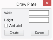
Figure 13.5 New dialog box for the
drawplatefunction
Renaming the Existing drawplate Function
AutoCAD has a few command-naming conventions, and one of those conventions includes prefixing command names with a hyphen. When an AutoCAD command displays a dialog box, often a second command has been created that carries the same name but is prefixed with a hyphen. Commands that are prefixed with a hyphen allow you to access most of the functionality of a dialog box from the Command prompt through a series of prompt options. Before implementing a new version of the drawplate function that displays a dialog box, you must rename the existing drawplate function to conform to the established AutoCAD command-naming standards.
The following steps explain how to rename the drawplate function to -drawplate:
- In the Visual LISP Editor, click File Open File.
- In the Open File To Edit/View dialog box, click the Files Of Type drop-down list, and choose Lisp Source Files.
- Browse to and select the
drawplate.lspfile and click Open. - In the text editor area, revise the boldface text:
; Draws a rectangular plate that is 5x2.75 (defun c:-drawplate( / pt1 pt2 pt3 pt4 width height insPt textValue cenPt1 cenPt2 cenPt3 cenPt4 old_vars hole_list) - Revise the boldface text:
; Register the help file for F1/contextual help support(if (findfile "DrawPlate.htm")(setfunhelp "c:-drawplate"(findfile "DrawPlate.htm"))) - Click File Save.
Defining a New drawplate Function
Now that you have renamed the existing drawplate function to -drawplate and defined the drawplate.dcl file, it is time to implement a new version of the drawplate function.
The following steps explain how to add the new version of the drawplate function that will display the Draw Plate dialog box:
- Open the Visual LISP Editor and the
drawplate.lspfile if they are not currently open. - In the text editor area, scroll to the bottom of the file and add the following code:
; Draws a rectangular plate and gets input from a dialog box (defun c:drawplate ( / dialog_name id status pt1 pt2 pt3 pt4 width height label insPt textValue cenPt1 cenPt2 cenPt3 cenPt4 old_vars hole_list) ; Define the width, height, and label for the plate (if (= *drawplate_width* nil)(setq *drawplate_width* 5.0)) (if (= *drawplate_height* nil)(setq *drawplate_height* 2.75)) (if (= *drawplate_label* nil)(setq *drawplate_label* "1")) ; Get recently used values from the global variables (setq width *drawplate_width*) (setq height *drawplate_height*) (setq label *drawplate_label*) (setq dialog_name "drawplate") ; Load the DCL file named ex_hidden.dcl (setq id (load_dialog (strcat dialog_name ".dcl"))) ; Create the dialog box (new_dialog dialog_name id "" '(-1 -1)) ; Set the default values of the width and height (set_tile "txt_width" (rtos width)) (set_tile "txt_height" (rtos height)) ; Set the default for the label (set_tile "chk_label" label) ; Add the actions to the Cancel and Create button (action_tile "cancel" "(done_dialog 0)") (action_tile "btn_create_object" "(setq width (atof (get_tile "txt_width"))) (setq height (atof (get_tile "txt_height"))) (setq label (get_tile "chk_label")) (done_dialog 1)" ) (setq status (start_dialog)) ; Unload the dialog box (unload_dialog id) ; Check the status returned (if (= status 1) (progn (setq old_err *error* *error* err_drawplate) ; Command function being used in custom error handler (*push-error-using-command*) ; Store and change the value of the system variables (setq old_vars (get-sysvars '("osmode" "clayer" "cmdecho"))) (set-sysvars '("osmode" "clayer" "cmdecho") '(0 "0" 0)) (command "._undo" "_be") ; Create the layer named Plate or set it current (createlayer "Plate" 5) (setvar "clayer" "Plate") (setq basePt (getpoint " Specify base point for plate: ")) ; Set the coordinates to draw the rectangle (setq pt1 basePt ;| lower-left corner |; pt2 (list (+ (car basePt) width) (cadr basePt) 0) ;| lower-right corner |; pt3 (list (+ (car basePt) width) (+ (cadr basePt) height) 0) ;| upper-right corner |; pt4 (list (car basePt) (+ (cadr basePt) height) 0) ;| upper-left corner |; ) ; Draw the rectangle (createrectangle pt1 pt2 pt3 pt4) ; Create the layer named Holes or set it current (createlayer "Holes" 1) (setvar "clayer" "Holes") ; Calculate the placement of the circle in the lower-left corner ; Calculate a new point at 45 degrees and distance of 0.7071 from pt1 (setq cenPt1 (polar pt1 (/ PI 4) 0.7071)) ; Calculate the next point from cenPt along the same angle ; as the line drawn between pt1 and pt2, and 1 unit less ; than the distance between pt1 and pt2 (setq cenPt2 (polar cenPt1 (angle pt1 pt2) (- (distance pt1 pt2) 1))) ; Calculate the final two points based on cenPt1 and cenPt2 (setq cenPt3 (polar cenPt2 (angle pt2 pt3) (- height 1)) cenPt4 (polar cenPt1 (angle pt1 pt4) (- height 1))) ; Append all the calculated center points to a single list (setq hole_list (append (list cenPt1) (list cenPt2) (list cenPt3) (list cenPt4))) ; Execute the createcircle function for each point ; list in the in the hole_list variable (foreach cenPt hole_list (createcircle cenPt 0.1875) ) (if (= "1" label) (progn ; Set the insertion point for the text label (setq insPt (getpoint " Specify label insertion point: ")) ; Define the label to add (setq textValue (strcat "Plate Size: " (vl-string-right-trim " .0" (rtos width 2 2)) "x" (vl-string-right-trim " .0" (rtos height 2 2)) ) ) ; Create label (createlayer "Label" 7) (setvar "clayer" "Label") (createtext insPt "_c" 0.5 0.0 textValue) ) ) ; Restore the value of the system variables (set-sysvars '("osmode" "clayer" "cmdecho") old_vars) ; Save previous values to global variables (setq *drawplate_width* width) (setq *drawplate_height* height) (setq *drawplate_label* label) (command "._undo" "_e") ; Restore previous error handler (setq *error* old_err) ; End using *push-error-using-command* (*pop-error-mode*) ) ) ; Exit "quietly" (princ) ) - Click File Save.
Testing the drawplate.lsp Changes
The following steps explain how to test the -drawplate function in the drawplate.lsp file:
- Create a new drawing.
- Start the
apploadcommand. Load the LSP filesdrawplate.lspandutility.lsp. If the File Loading - Security Concern message box is displayed, click Load. - At the Command prompt, type
-drawplateand press Enter. - At the
Specify base point for the plate or [Width/Height]:prompt, typewand press Enter. - At the
Specify the width of the plate <5.0000>:prompt, type3and press Enter. - At the
Specify base point for the plate or [Width/Height]:prompt, typehand press Enter. - At the
Specify the height of the plate <2.7500>:prompt, type4and press Enter. - At the
Specify base point for the plate or [Width/Height]:prompt, pick a point in the drawing area to draw the plate and holes based on the width and height values specified. - At the
Specify label insertion point:prompt, pick a point in the drawing area below the plate to place the text label.AutoCAD draws the completed plate, as expected.
The following steps explain how to test the revised version of the drawplate function:
- At the Command prompt, type
drawplateand press Enter.The Draw Plate dialog box is displayed and uses the width and height values specified by the
-drawplatefunction. - In the Draw Plate dialog box, in the Width text box, enter
5. - In the Height text box, enter
5. - Clear the Add Label check box.
- Click Create.
- At the
Specify base point for the plate or [Width/Height]:prompt, pick a point in the drawing area to draw the plate and holes based on the width and height values specified.AutoCAD draws the completed plate without the label, as expected.
- At the Command prompt, type
drawplateand press Enter. - In the Draw Plate dialog box, select Add Label.
- Click Create, and specify the insertion point for the plate and label.
AutoCAD draws the completed plate with a label this time.