
Chapter 1
Establishing the Foundation for Drawing Standards
Drawing standards, also known as CAD standards, are guidelines that help you name the files that are created inside or outside of the Autodesk® AutoCAD® software for a project, the named objects that are used within a drawing file, and the file formats that you might accept. Much like the marketing or management teams use the same logos and memo templates, all drafters or professionals using AutoCAD software in your company should follow a set of company standards.
Without having a well-defined set of standards, you will find it harder to share and output files within a company, and in turn this can lead to delays and make it nearly impossible to achieve a consistent look to all the drawings that your client receives. In addition, it is difficult to customize AutoCAD to help enforce your company's standards if there really are no standards.
Can you imagine what a client might think when a company sends them a set of drawings that contain different fonts or title blocks, or the inconsistent use of lineweights?
Well-established drawing standards ensure that your drawings all look the same when they are presented to the client, and they can make it easier to
- Train new drafters and other professionals on your company's standards that use AutoCAD
- Identify which drawing and externally referenced files are associated with a project
- Determine the purpose of a named object in a drawing
- Share project files with clients and contractors because your standards are well defined
Naming Standards for Projects and Files
As you might have gathered, it is not in your company's best interest to let everyone define their own drafting standards; this same approach applies to naming standards for projects or the files associated with a project, and how files should be stored. At the end of the day, the files created are owned by the company, and there is a pretty good chance that more than one individual will be working on a project over its entire lifetime. There is nothing more frustrating than when changes to a project are requested and the files can't be located because they are missing or no one understands how the files were saved.
The first step your company should consider if you have no current file-naming standard, or if you are considering a change to your existing system, is a way to log and name a project. Project logging can be as simple as posting a spreadsheet on the network drive or using a project-collaboration site on Microsoft SharePoint to ensure everyone is logging projects using the same system. Once the logging system is determined, you can determine how projects and files should be named. As with the project-logging system, all files should be stored in a central location on a networked drive or a system that allows you to check files in and out, such as Autodesk Vault.
You can take two approaches to the way you name projects and files: you can establish a system yourself using the guidelines that I offer in the next few sections, or you can use the standards set by a consortium or other professional governing body. Based on your industry or the country you work in, you might consider the guidelines established by the American Institute of Architects (www.aia.org), National Institute of Building Sciences (www.nibs.org), Royal Institute of British Architects (www.architecture.com), or American National Standards Institute (www.ansi.org).
Project Names
The project-naming structure you choose to use should be short and sequential. For example, you might consider just a basic numeric value such as 000001, 000002, and so on. I do not recommend that you use the year as part of the numbering system since projects can span multiple years.
Project names commonly include an alphabetic prefix with one or more letters to make it easy to start a secondary naming system if you decide to organize your projects by business type or some other classification. For example, say your company works on residential, commercial, and government projects. In this case, you might consider prefixing the project's number with R, C, or G, so they would be R00001, C00002, or G00003.
Other information you might want to represent as part of a project name could be
Phase
Often a numeric value of one alphabetic letter or number (for example, -A or -1 to represent the first phase of a project).
Location
Optional; often a combination of alphabetic letters and numbers to help identify multiple locations on a single and very large job site (for example, -A1 to represent the first location and -B1 to represent a second location). Using a Building attribute in a filename might be a better choice for you since all work is being done under a single project instead of multiple projects for a single job.
If a project has only a single phase, it is up to you to determine whether you want to indicate that as part of a project name. A project always has a first phase, but it might never have a second phase, based on the size of the project. Information such as floor, discipline, file type, and sheet type should be reserved for use by files within a project and not included as part of a project's name. Figure 1.1 shows what a structure for a project number might look like.
Figure 1.1 Possible project numbering structure
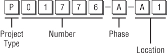
The project-naming information I've presented is only one of many possible ways you can define the numbers for your projects. Just keep in mind that project numbers should be short and sequential. No matter how you choose to name your projects, be sure to document your system and follow it for every project you create. Documenting the system will be important for those inside and outside your company.
After you have defined the requirements and structure for your project name, assign that name to the folder on the network in which all files related to that project should be stored. Alternatively, you can use the name as an attribute in your file-management system of choice.
Filenames
There are two schools of thought when it comes to naming the files that are part of a project: one is to include the project name as part of the filename and the other is not to include it, since it is already the project folder's name. I subscribe to the school of thought that a project name should be part of a file's name, and my main reason is that a file can accidentally be placed in the wrong project folder. If the project name is not part of the filename, the file in a way could be lost forever. No matter which approach you choose, you will want to be consistent. Either prefix all your files with the project name, or don't.
Similar to a project name, the files in a project should use consistent, short, and meaningful names. A basic filename might contain the following information:
Discipline
Often a single letter that represents the main discipline that the drawing is used by (for example, A for Architecture, C for Civil, M for Mechanical, or S for Structural).
Secondary Discipline
Often a single alphabetic letter that helps provide an additional level of classification for the file based on the designated main discipline (for example, D for details, G for grading, L for lighting grid, or S for sitework).
Sheet/File Type
Often a single alphabetic letter used to identify the contents of a file—for example, -P for plans, -G for columns grid, and -I for images. The same can also be represented by numbers—for example, -1 for plans, -0 for columns grid, and -9 for images. You might want to consider also adding an -X when the file should be used only as an external reference across multiple drawing files.
Sheet Number
Often a sequential numeric value of two numbers that range from 00 through 99 to uniquely identify a file from other files that might contain all the same file attributes in the project (for example, 01 or 76).
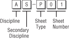
Figure 1.2 shows a possible structure for a filename based on the file information described.
Figure 1.2 Possible file-naming structure
The following is some additional information you might want to consider adding to your filenames:
Sheet Size
Optional; often a single alphabetic letter used in combination with the sheet number to represent the paper size that the file should be output on (for example, A for an ANSI A-size [8 1/2″ × 11″] or D for an Architectural D-size [24″ × 36″]).
Building
Often a single alphabetic letter used in combination with floor to indicate which building the file belongs to (for example, -A or -B).
Floor
Often two numbers to indicate which floor of a building the file belongs to (for example, -01 or -22).
Area
Optional; a single alphabetic letter used in combination with floor to help identify a specific area on a floor when a floor is broken up into one or more files (for example, A or C).
Revision
Often the letter R or RV followed by a numeric value to represent the current revision level of a file (for example, -R1 or -RV03). Using revision numbers in a filename has its pros and cons. One of the benefits is that you can go back to an earlier revision of a design if you do not use a system that supports version tracking. The downside is that it affects the other drawings that might reference the drawing; to avoid this, you could create a copy of the drawing being revised and rename the copied file to include the revision number in its name.
Not all of the attributes will make sense for each discipline. For example, a civil drawing will most likely not contain a Building or Floor attribute, but it might contain an Area. So, it is possible that you might use different file-naming structures for different disciplines in your company. If you use different naming structures for different disciplines, be sure the attribute values have the same meaning across the entire company. For instance, do not use numbers to indicate Areas for civil, and alphabetic letters for the architectural drawings.
Managing Standards with Drawing Templates
When you create a new drawing, you have two choices: start from scratch or use a drawing template (DWT) file. Starting from scratch, or using the default drawing that is created when AutoCAD first starts up, is not ideal as it most likely does not conform to your company's standards and the settings can change from release to release. The same is true for the drawing template files that come with AutoCAD: you can use them, but they are not tailored to your company's standards. The default drawing templates make for an excellent starting point, but you should create your own drawing template files so that you know what's in them.
What Is a Drawing Template?
A drawing template is a file that contains the objects, styles, unit of measurement, and other settings that should be used when creating a new drawing with the new or qnew commands. It has a file extension of .dwt. Prior to drawing templates, they were called prototype drawings; you should know that just in case you hear that term come up in a conversation with an AutoCAD veteran.
When a new drawing is created using a DWT file, the DWT file is copied into memory as a new drawing and the DWT file remains unchanged. A DWT file is identical to a drawing (DWG TM) file. While you commonly use the saveas command to save a DWG file as a DWT file, you could also just change the file extension of a DWG file from .dwg to .dwt and achieve the same results.
The following steps explain how to save a DWG file as a DWT file using AutoCAD on Windows:

If you are using AutoCAD on Mac OS, use the following steps:
Units of Measurement and Format
The drawings that you create in AutoCAD are based on one of two systems of measurement: Imperial or English, and metric. Imperial measurement is based on inches, and metric measurement is based on meters. The system of measurement that a drawing currently uses is stored in the measurement system variable; 0 (Imperial units) or 1 (metric units). Changing the value of the measurement system variable does not affect the objects that are already in a drawing. Resizing objects in a drawing to fit the new system of measurement can be done with the scale command.
The measurement system does not affect the formatting of linear and angular units, but it does control the following:
- The default drawing template used for the initial drawing that is created when AutoCAD first starts up: acad.dwt for Imperial measurement and acadiso.dwt for metric measurement
- Which hatch pattern and linetype definition files AutoCAD looks for in its support-file search paths: acad.pat and acad.lin for Imperial measurement and acadiso.pat and acadiso.lin for metric measurement
- The current measurement choice of the Scale List area in the Default Scale List dialog box of the Options dialog box (Windows) and Application Preferences dialog box (Mac OS)
The current measurement system does not affect the way linear and angular drawing units are accepted or displayed. Drawing-unit formatting is controlled by several settings, which you can change by using the Drawing Units dialog box (units command); see Figure 1.3.
Figure 1.3 Drawing Units dialog box. The Windows version of the dialog box appears on the top the Mac OS version appears on the bottom.
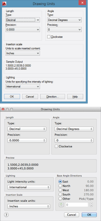
Each of the settings shown in the Drawing Units dialog box can also be accessed using system variables. Understanding the relationship between many of the AutoCAD dialog boxes and the system variables they represent will help you automate tasks related to drawing setup, configure drafting aids, and control the default behavior of commands. Table 1.1 explains the system variables that can be changed using the Drawing Units dialog box.
Table 1.1 System variables
| Variable | Controls |
| lunits | Current linear unit mode |
| luprec | Number of decimal places or the precision in which linear units should be displayed |
| aunits | Current angular unit mode |
| auprec | Number of decimal places or the precision with which angular units should be displayed |
| angdir | Positive direction for angles relative to the active User Coordinate System (UCS) |
| angbase | Direction of Angle 0 relative to the active UCS |
| insunits | Units used to properly scale an image or block being attached or inserted into the drawing |
| lightingunits | Controls the use of generic or photometric lighting along with the lighting units that should be used when rendering the drawing |
You can learn more about system variables, including how to change their values, later in this chapter in the section “Working with System Variables.” For now, just understand that system variables play an intricate part in being able to customize AutoCAD.
Graphical and Named Objects
As I previously mentioned, a drawing template (DWT) file is the same as a drawing (DWG) file; it can contain both graphical and nongraphical objects. The graphical and nongraphical objects in a DWT file should be limited in number and common to all the new drawings you create. If you have named objects that might be less frequently used, you could store them in a drawing file and then insert that drawing into your drawing to inherit the additional named objects. Or you may choose to automate the creation process of the named objects using one of the available customization methods mentioned later in this book. I cover the creation and management of named objects in Chapter 2, “Working with Named Objects.”
Most DWT files have no objects in model space but do have objects placed on one or more of the named layouts in the file. Named layouts commonly have viewports as well as a number of objects or a single block that defines a title block used to frame your design when outputting. The title block could be an external reference (xref) or a block that has already been defined within the DWT file. I cover defining blocks in Chapter 3, “Building the Real World One Block at a Time.” General notes, callouts, symbols, and a revision table are other objects that you might place on a layout as well in your DWT file.
The named objects that you should add to your DWT files are as follows:
- Blocks
- Detail view styles
- Dimension styles
- Layers
- Linetypes
- Multileaders
- Multiline styles
- Section view styles
- Table styles
- Text styles
If you work on 3D models, you might also want to consider including UCSs, model-space viewports, saved views, materials, and visual styles. I cover the creation and management of named objects in Chapter 2.
Organize Output with Layouts
Each drawing template (DWT) file contains at least one named layout, and it is a good practice to make sure that the layout is ready to be plotted after a drawing is created using the drawing template. A drawing template can contain more than one layout, but each layout should add some value. If you need additional layouts in your drawing, you could use the layout command to duplicate a layout that already exists in the drawing or to import a layout from another drawing file.
The layouts in a drawing template should contain the following:
- Page-setup settings that define the output device, paper size, and other settings that impact the layout when it is plotted or published. I cover configuring plotter devices and plot styles in the section “Defining Plotter Configurations and Plot Styles” later in this chapter.
- A title block that contains all the informational fields needed to identify the drawing once it is plotted or published. A title block might include your company name and address, project name and address, part number, scale, and other information that helps identify the drawing. I discuss creating blocks and attributes in Chapter 3.
- One or more floating viewports that define which areas of model space should be plotted as part of the layout, along with the scale the objects in the viewports should be viewed at.
You might also want to consider adding the following to a drawing for use with or on a layout:
- General notes or disclaimers, and viewport labels that each or most of the drawings created with the drawing template might contain.
- A border around the margins of the paper. The viewports, title block, and other objects on the layout should be inside the border.
- A plot stamp that indicates when the drawing was plotted and the name of the source drawing file.
- Dimension and text styles set up for adding dimensions and annotation to a layout. Remember that layouts are plotted at a 1:1 scale, so the styles need to be defined correctly.
Working with System Variables
System variables in many ways are like the keys hiding under the doormat at the front door of a house. They allow you to directly access many of the settings that can be used to manipulate the AutoCAD environment and control how commands work, instead of you resorting to a dialog box or using options with a command. The values of system variables are stored in one of two places: with the drawing or as part of the user's AutoCAD profile. The user's AutoCAD profile is stored in the Windows Registry, or in several Plist files on Mac OS.
You use the setvar command to list and change the current value of a system variable. After you start the setvar command, you can enter the name of the system variable to work with or ? (question mark) to return a list of all values or a filtered list using a wildcard match of the system variables that are supported.
The following steps explain how to list and change the value of a system variable:
You can list all supported variables by doing the following:
Managing Drawing Template Files
After you spend the time creating and customizing your drawing template (DWT) files, you will want to make sure that all users in your company have access to them. By default, AutoCAD looks in a local folder on each workstation for the DWT files it can use. This local folder is specified in the Options dialog box (Windows) or Application Preferences dialog box (Mac OS).
Using a local folder is not ideal for maintaining these files; it is best to change the location AutoCAD looks in to a folder on a networked drive. A networked folder makes it easy to update your drawing template files; post the files once, and then everyone always has access to the latest version.
If you need to use a local folder for your DWT files—when you have remote users, for example—it is good practice to keep your customized files separate from those that come with AutoCAD. Doing so makes it easy to back up your custom files and also removes the temptation to stray from your company's CAD standards. The recommended process for managing local DWT files is to first create a company folder on the local drive, and then create a Template subfolder and add your DWT files to the Template folder. Keeping the files synchronized from a network or remote server can be done using a batch (BAT) or BASH script (SH), Windows Task Scheduler event, or login script to synchronize the files from a network or remote server.
Follow these steps to specify a different folder for AutoCAD on Windows to look in for DWT files:
- On the keyboard, press the Windows+E key combination, or right-click in the lower-left corner of the screen (not the AutoCAD application window) and click Windows Explorer or File Explorer, based on your operating system.
- In Windows Explorer or File Explorer, navigate to the folder where you want to store your DWT files.
- Right-click in an empty area in the Folders/Files list and click New Folder. Enter the name Templates or the name you want to use. Press Enter to accept the new name.
If you are using AutoCAD on Mac OS, use these steps:
- In the Mac OS Dock, click Finder or from the desktop click File → Computer.
- In Finder, navigate to the folder where you want to store your DWT files.
- Ctrl-click or secondary-click in an empty area in the Folders/Files list and click New Folder. Enter the name Templates or the name you want to use. Press Enter to accept the new name.
In addition to specifying the location of the Select Template dialog box, you can specify the default DWT file that is used with the qnew (Quick New) command. You specify the DWT file for the qnew command using the Options dialog box (Windows) or Application Preferences dialog box (Mac OS).
Use these steps to specify which DWT file should be used when the qnew command is executed in AutoCAD on Windows:
If you are using AutoCAD on Mac OS, use the following steps:
Choosing a File Format for Your Drawings
Out of the box, AutoCAD saves all the drawings you create or open to the latest file format. This is done to ensure that any of the objects you create are properly stored and can be restored when the drawing is opened later. Using the current drawing file format is not always the best choice; perhaps you are working with another department that needs access to the drawings you create and they are still on an older release, or the contract you are bidding on requires all the files for a project to be submitted in a specific format.
No matter the reasoning, AutoCAD allows you to set the default file format it uses when saving a drawing instead of requiring you to change to an earlier format from the Files Of Type (Windows) or File Format (Mac OS) drop-down list in the Save Drawing As dialog box. The default file format for a drawing can be set in the Options dialog box (Windows) or Application Preferences dialog box (Mac OS).
Follow these steps to change the default file format used when saving a drawing file in AutoCAD on Windows:
If you are using AutoCAD on Mac OS, use the following steps:
Table 1.2 shows which file format you should use to save your drawings so that users on an older release can open your files.
Table 1.2 AutoCAD releases and drawing file formats
| Autocad Release(S) | Drawing File Format |
| AutoCAD 2013 and AutoCAD 2014 | AutoCAD 2013 |
| AutoCAD 2010, AutoCAD 2011, and AutoCAD 2012 | AutoCAD 2010 |
| AutoCAD 2007, AutoCAD 2008, and AutoCAD 2009 | AutoCAD 2007 |
| AutoCAD 2004, AutoCAD 2005, and AutoCAD 2006 | AutoCAD 2004 |
| AutoCAD 2000, AutoCAD 2000i, and AutoCAD 2002 | AutoCAD 2000 |
| AutoCAD Release 14 | AutoCAD R14 |
| AutoCAD Release 13 | AutoCAD R12 DXF |
| AutoCAD Release 12 | AutoCAD R12 DXF |
If you want to make sure that all the files in a project are saved in a specific file format, you can use one of the following tools:
Autodesk DWG TrueView
A drawing file conversion program that is standalone from AutoCAD. It's available on Windows only and can be downloaded from www.autodesk.com/dwg.
AutoCAD 360
Online collaboration website that allows you to view, edit, and share DWG files with others on a project. After a drawing has been uploaded, it can be downloaded in a different file format. The AutoCAD 360 website can be found at https://www.autocadws.com/.
ETRANSMIT command
Command that can be used to resave all the drawing files in a sheet set, or in the drawing files you add to the Create Transmittal dialog box. It's available on Windows only.
Script Pro
Utility that allows you to run script files on selected drawing files. The utility is available for Windows only and can be downloaded from here:
http://usa.autodesk.com/adsk/servlet/item?siteID=123112&id=4091678&linkID=9240618
Script Files and SCRIPT command
You can create a script file that opens, saves, and closes multiple drawing files. I cover creating script files in Chapter 8, “Automating Repetitive Tasks.”
Defining Plotter Configurations and Plot Styles
Plotting, printing, and publishing are all forms of outputting a drawing file to a hardcopy (a physical sheet of paper) or an electronic representation of a hardcopy. Doing so helps you keep your intellectual property in your drawings secure, and it also gives those that do not have access to or know how to use AutoCAD the ability to review and approve your drawings.
Before you can output a drawing, you need to
- Set up an output device
- Define the plot styles that control the way drawing objects appear in the output
- Configure the settings of model space or a named layout
Configuring Output Devices
Setting up an output device is commonly handled by installing a system printer in Windows or Mac OS, but AutoCAD on Windows also supports a second option that allows you to configure a nonsystem printer using custom device drivers. Nonsystem printers are stored in PC3 files. Once a device is set up, additional settings can be specified inside AutoCAD to control the output being sent to the device. After a device is configured, you can then assign the device directly to a layout or page setup, or set it as the current device when using the plot command.
You can configure a nonsystem printer for use with AutoCAD on Windows by doing the following:
- My Computer: The device is configured to use a port on your local computer, to plot to a file, or to use an AutoSpool utility (an application that controls how the plot file is handled).
- Network Plotter Server: The device is configured by posting plot files to a network location where the plotter checks for new files that need to be plotted.
- System Printer: The device is configured to use an installed system printer and allows you to control the properties of AutoCAD-specific output settings.
- If you chose My Computer, the Plotter Model page is displayed. Select a manufacturer and one of the supported plotter models. Click Next.
- If you chose Network Plotter Server, the Network Plotter page is displayed. Enter or select the name of the network server (UNC) that you want to use, and click Next. The Plotter Model page is displayed. Select a manufacturer and one of the supported plotter models. Click Next.
- If you chose System Printer, the System Printer page is displayed. Select a printer that is installed under the operating system and click Next.
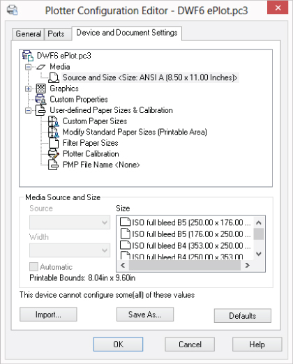
Figure 1.4 Editing a plotter configuration file
Do the following to edit a nonsystem printer in AutoCAD on Windows:
After a system printer is installed or a plotter configuration is created, you can use it to output the objects in model space or on a named layout. The following steps explain how to assign a plot configuration to a layout or page setup and how to use it with the plot command:
- For a layout or page setup, click the Application button → Print → Page Setup (Windows) or click File → Page Setup Manager (Mac OS). In the Page Setup Manager, select the layout or page setup you want to change, and then click Modify on Windows or click the Action menu (gear icon) → Edit on Mac OS to display the Page Setup dialog box. In the Page Setup dialog box, in the Printer/Plotter area, choose a device from the Name (Windows) or Printer (Mac OS) drop-down list. Click OK. Click Close to exit the Page Setup Manager.
- For plotting or printing with the plot command, click the Application button → Print (Windows) or click File → Print (Mac OS). In the Plot dialog box (Windows) or Print dialog box (Mac OS) in the Printer/Plotter area, choose a device from the Name (Windows) or Printer (Mac OS) drop-down list. Click OK (Windows) or Print (Mac OS) to output the drawing.
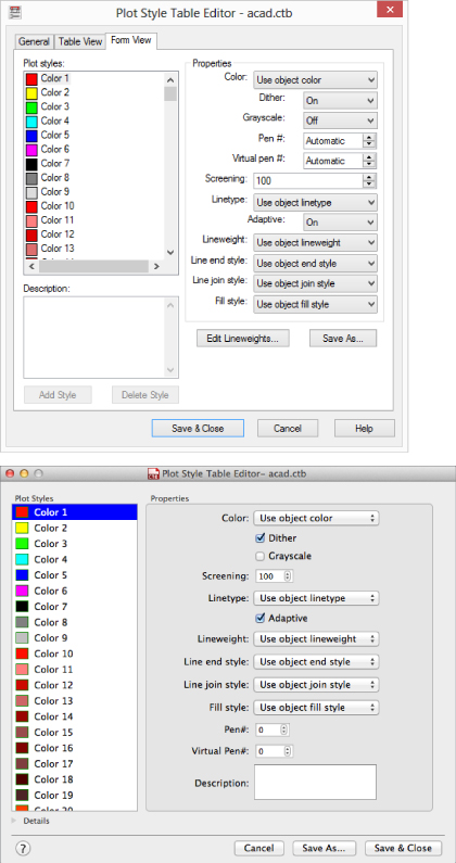
Using and Creating Plot Styles
Plot styles are used to control the way drawing objects appear onscreen and when they are output to hardcopy (a physical sheet of paper) or an electronic representation of a hardcopy. AutoCAD supports two types of plot styles: color dependent and named.
Color-dependent plot styles, stored in CTB files, are the most common of the two styles that AutoCAD supports. They are the way object properties were applied during plotting in AutoCAD prior to the introduction of named plot styles in AutoCAD 2000. With color-dependent plot styles, as the name reflects, the color assigned to an object in a drawing controls the object properties that are assigned during plotting. Even though your drawings can use true colors, plot styles are based on the AutoCAD Color Index (ACI) system of 255 colors, and true color values are therefore mapped to their nearest ACI value when plotting.
Named plot styles, stored in STB files, are the newest way to control object properties when plotting. First introduced in AutoCAD 2000, this style uses a name-based system instead of being dependent on the color of an object. Although this might sound ideal, there are a few places where color can be assigned only to objects in a drawing or style. For example, you can only set the color of the grid lines in a table or the dimension line of a dimension style.
Both types of plot styles have their advantages. Color dependent is based on the legacy system and is thus compatible with decades of drawings, making it the clear choice for most companies. It is also the style that provides the most control over complex objects and many styles. Switching to named plot styles requires a bit of planning and time, which at the end of the day keeps it from being an option for many companies. Here are a few of the issues you need to consider if you plan on adopting named styles:
- Existing block libraries need to be updated to ensure they display correctly using named plot styles.
- Dimension and table styles might need to be updated to ensure they use a single color and that they use lineweights and linetypes to control the way they output.
- Color-dependent drawings need to be updated to use named plot styles with the convertpstyles command. Having a mix of plot styles in the same project does not give your drawings a consistent look when they are plotted.
You can create a plot style on Windows by doing the following:
- Start From Scratch: Use this option when you want to create a new color-dependent (CTB) or named (STB) plot style file.
- Use An Existing Plot Style Table: This option creates a copy of an existing CTB or STB file, and then allows you to edit the copied file.
- Use My R14 Plotter Configuration (CFG): If upgrading from AutoCAD Release 14, you can import your settings to create a new plot style file.
- Use A PCP Or PC2 File: If you have a PCP or PC2 file that was exported from an earlier release, you can import the pen table properties and create a new plot style file.
Figure 1.5 Editing a plot style file. The Windows version of the dialog box appears on the top and the Mac OS version on the bottom.
If you are using AutoCAD on Mac OS, use the following steps to create a new plot style file:
If you want to make changes to an existing plot style file, do the following:
After a plot style has been created, you can use it control how the objects of your drawing appear when output. The following steps explain how to assign a plot style to a layout or page setup, and how to use it with the plot command:
- For a layout or page setup, click the Application button → Print → Page Setup (Windows) or click File → Page Setup Manager (Mac OS). In the Page Setup Manager, select the layout or page setup you want to change, and then click Modify on Windows or click the Action menu (gear icon) → Edit on Mac OS to display the Page Setup dialog box. In the Page Setup dialog box, in the Plot Style Table area, choose a plot style from the drop-down list. If prompted to apply the plot style to all layouts, click Yes. On Mac OS only, you might need to click the More Options button in the lower-right corner of the dialog box to see the Plot Style Table area. Click OK. Click Close to exit the Page Setup Manager.
- On Windows, for plotting with the plot command, click the Application button → Print. In the Plot dialog box, click the More Options button in the lower-right corner of the dialog box. In the Plot Style Table area, choose a plot style from the drop-down list. Click OK to output the drawing.
- On Mac OS, for printing with the plot command, click File → Print. In the Print dialog box, in the Page Setup area, click Edit Page Setup. In the Page Setup dialog box, in the Plot Style Table area, choose a plot style from the drop-down list. You might need to click the More Options button in the lower-right corner of the dialog box to see the Plot Style Table area. Click Print to output the drawing.
Managing Plotter Configuration and Plot Style Files
After you have added your output devices and created your plot styles, you will want to make sure that all users in your company have access to them. By default, AutoCAD looks in local folders on each workstation for the PC3, CTB, and STB files that it might need to output your drawing files. These local folders are specified in the Options dialog box (Windows) or Application Preferences dialog box (Mac OS). As with other custom files, such as DWT files, you should place all your common plotter configuration and plot style files on a network location.
Follow these steps to specify different folders for AutoCAD on Windows to look in for PC3 and CTB/STB files:
If you are using AutoCAD on Mac OS, use the following steps:
Enforcing CAD Standards
CAD standards enforcement is a gradual process if you are not doing it today. The best strategy you have is positive reinforcement and coaching. At the end of the day, your drafters and professionals need to want to follow all the established standards. It can be tempting to take the quick and easy route to get a job done, but shortcutting a process can have unexpected consequences, such as a custom tool not working in a drawing and resulting in manual steps or a drawing not plotting correctly. After all, a process works each and every time only when each step is completed properly.
There are steps you can take to help make following CAD standards easier for the drafters and professionals you support. You can use these methods to apply and enforce your company's standards:
User-Interface Customization
AutoCAD offers an interface that can be customized to the way your company works. You can create ribbon buttons or menu items that use a custom macro to set a layer or style as current before starting a command. Customizing the user interface is covered in Chapter 5, “Customizing the AutoCAD User Interface for Windows,” and Chapter 6, “Customizing the AutoCAD User Interface for Mac.”
Scripts
Script files are a great way to execute multiple commands and options in a specific order using predefined values without needing to understand a programming language. You can create layers and styles, insert a title block on a specific layer, or even change your current drafting settings. Creating script files is discussed in Chapter 8.
Action Macros
Created using the Action Recorder, action macros are a modern take on script files. They allow you to execute multiple commands and options in a specific order, but they are created interactively while you use AutoCAD. After an action macro is created, it can be executed in other drawing files. Recording action macros is covered in Chapter 8. (Action macros are not available on AutoCAD for Mac OS.)
Custom Programs
The programming languages that AutoCAD supports give you the most flexibility in enforcing CAD standards. Custom programs can be created to make sure a specific layer is current before a command is started, whether the user starts the command from the user interface or from the command prompt.
You can also use custom programs to step through the objects in a drawing and make sure they conform to your standards, and much more.
Tool Palettes
An arrangement of tools in the Tool Palettes window allows you to create objects using specific property settings. You can create a Note tool that uses a specific combination of text style and layer for general notes and define another tool for disclaimers; access and insert commonly used blocks at a set scale; or fill an enclosed area with a hatch pattern, using a specific lineweight and color. I discuss tool palettes in Chapter 7, “Creating Tools and Tool Palettes.” (The Tool Palettes window is not available on AutoCAD for Mac OS.)
DesignCenter™
DesignCenter allows you to access the named objects defined in a drawing and add them to your current drawing. It also allows you to insert blocks as well as attach external drawings and raster images. I do not cover using DesignCenter in this book; use the AutoCAD Help to learn more about this feature. (DesignCenter is not available on AutoCAD for Mac OS.)
Content Explorer™
Content Explorer is a modernized version of DesignCenter that allows you to locate named objects from other drawing files on a network and add them to your current drawing. I do not cover configuring and using Content Explorer in this book; use the AutoCAD Help to learn more about this feature. (Content Explorer is not available on AutoCAD for Mac OS.)
AutoCAD on Windows offers multiple tools that are designed to help you validate named objects and their properties in a drawing against those defined in a drawing standards (DWS) file. These tools are as follows:
Standards Manager
Used to configure and validate a drawing file for standards violations. Violations found can be fixed to conform to the standards you are validating against.
Batch Standards Checker
Validates the standards in a set of drawing files and generates a report of all the violations found and which drawing files they were found in. You must open each drawing file manually in order to fix the violations found.
Layer Translator
Used to create layer mappings and align the layers of a drawing with those defined in your standards.
Drawing Standards (DWS) Files (Windows Only)
A drawing standards (DWS) file is the same as a drawing or a drawing template file, with the exception of the content it contains and its file extension. A DWS file commonly does not contain any graphical objects, but it does contain all of the named objects that are used to define your CAD standards and your layer translation mappings for the Layer Translator. For more information on named objects, see Chapter 2. I cover the Layer Translator in the “Translating Layers (Windows Only)” section later in this chapter.
At a minimum, your DWS files should contain the following named objects:
- Dimension styles
- Layers
- Linetypes
- Text styles
These steps explain how to save a DWG file to a DWS file using AutoCAD on Windows:
Drawing standards (DWS) files are always saved in the latest file format. If you support multiple releases of AutoCAD in your company, you will want to instead save your standards to a DWG file with the oldest file format required. Once the DWG file is created, you can then just change the file's extension through the operating system.
Configuring, Checking, and Fixing Drawing Standards (Windows Only)
The AutoCAD Standards Manager provides you with the ability to check several of the named object types in a drawing against those defined in a drawing standards (DWS) file. Using the Standards Manager requires the completion of two distinct processes: first, you associate one or more DWS files that contain your CAD standards with the current drawing, and second, you check and fix any standards violations found.
Configuring Standards
Configuring a drawing to be checked for standards violations requires you to associate the DWS files that contain your CAD standards and specify which plug-ins you want to use. A plug-in defines the comparison rules that should be used to find any standards violations in the current drawing against the approved CAD standards in the DWS files. You can choose from one of four plug-ins that come with AutoCAD, you can obtain plug-ins from third-party developers, or you can develop your own plug-ins using the CAD Standards Plug-in API. You associate DWS files with a drawing using the standards command, which displays the Configure Standards dialog box.
The following steps explain how to associate a DWS file with a drawing and specify which standards plug-ins to use:
Figure 1.6 Configuring drawing standards files
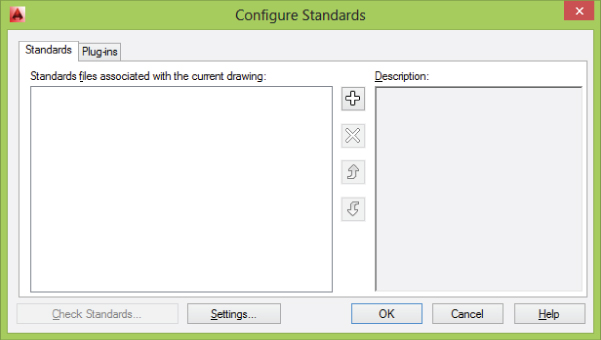
Figure 1.7 Enabling the plug-ins to use when validating drawing standards
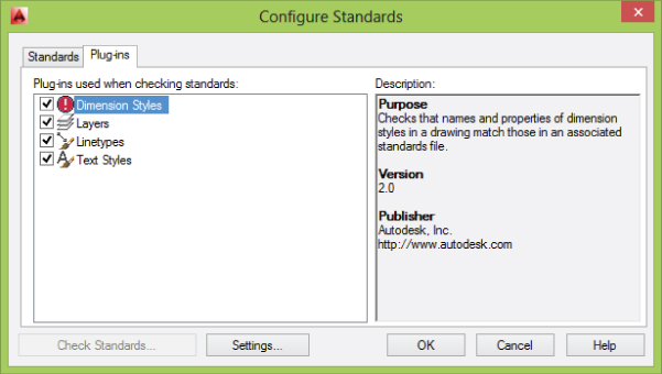
Figure 1.8 Changing the notification and Check Standards settings
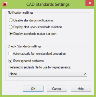
Figure 1.9 Access to CAD Standards notifications and settings is just a click away.
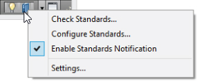
Checking For and Fixing Standards Violations
After you have associated at least one DWS file to a drawing and specified which plug-ins to use, you can check your drawing for standards violations. While you are checking for standards violations, each plug-in is executed one by one, and how a plug-in checks for standards violations can vary between plug-ins.
The standard four plug-ins that come with AutoCAD compare the name of an object in the current drawing to the names of objects in the associated DWS files. When a match is found, AutoCAD checks to see whether the properties of the two named objects are the same. If they are the same, AutoCAD moves on to the next named object and checks it. If the properties are different, you are asked to fix or ignore the standards violation. If no matching named object is found between the drawing and DWS files, you are prompted to select one of the approved named objects from the associated DWS files or ignore the standards violation.
Follow these steps to check a drawing for any standards violations:
Figure 1.10 Standards violation found
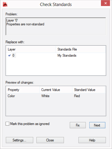
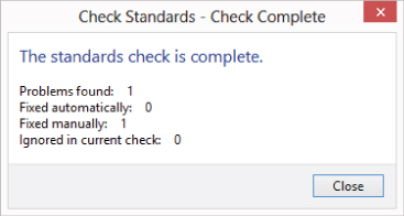
Figure 1.11 The check for standards violations is complete.
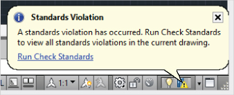
While working on a drawing with CAD standards configured, you might see the Standards Violation balloon (see Figure 1.12) come up. This indicates that something in the drawing conflicts with your company's standards. A custom routine might have caused the standards violation, or maybe you inserted a drawing that contains named objects that were not updated with the latest standards. Click the Run Check Standards link in the balloon to fix or ignore the standards violation.
Figure 1.12 Standards violation detected
Checking Drawings in Batches
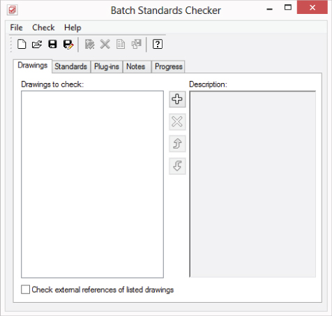
The Check Standards dialog box is efficient for checking the standards of the current drawing, but it is not ideal if you have five, ten, or even hundreds of drawings in your project that need to be checked. When AutoCAD is installed, it also installs an external utility called the Batch Standards Checker. The Batch Standards Checker allows you to select a number of drawings and check them against the standards defined in a DWS file.
The Batch Standards Checker allows you to check the drawing files using the DWS files that are already associated with each file, or you can specify which DWS files should be used. This utility uses the same plug-ins that are available in the Configure Standards dialog box. The one feature that the Batch Standards Checker does not support is the ability to fix any of the violations found; that must be done by opening each drawing and using the checkstandards command.
The following steps explain how to use the Batch Standards Checker:
- (Windows XP and Windows 7) Click the Windows Start button → [All] Programs → Autodesk → AutoCAD <release> → Batch Standards Checker.
- (Windows 8) On the Start screen, right-click and click All Apps. Under the AutoCAD <release> category, click Batch Standards Checker.
Figure 1.13 More than one drawing can be checked for standards violations with the Batch Standards Checker.
- The Check Each Drawing Using The Associated Standards Files option instructs the Batch Standards Checker to use the DWS files associated with each drawing file; if no DWS file is associated with a drawing file, the drawing is not checked for standards violations.
- Use the Check All Drawings Using The Following Standards Files option to specify which DWS files to use for validating the CAD standards. Click the + (plus) button to list which DWS files to use. If more than one DWS file is added, select an associated DWS file and click Move Up/Move Down to change the search order of the DWS files. Select a DWS file and click the X to remove an associated DWS file.
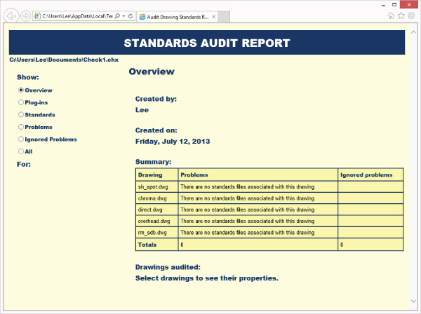
Figure 1.14 Use this report to determine which files contain standards violations so they can be fixed.
Translating Layers (Windows Only)
Checking a drawing for standards violations is great for ensuring the files in the projects you create conform to your CAD standards, but working with drawings from a client or subcontractor can make this a bit more challenging, especially when it comes to layer standards. Over a set of drawings, you might use a few different dimension or text styles, but over those same drawings you could be working with dozens or hundreds of different layers.
AutoCAD provides a tool called the Layer Translator that allows you to map a single layer or a group of layers to a single layer based on your established CAD standards. Once a translation map is defined, it can be saved to a drawing or drawing standards file to reuse on other files from the client. This tool can also be useful in transitioning from an old to a new layer standard that your company is implementing. The Layer Translator can be displayed using the laytrans command.
Follow these steps to define a layer translation map and translate the layers in the current drawing to those defined by your CAD standards:
Figure 1.15 Translating layers between CAD standards
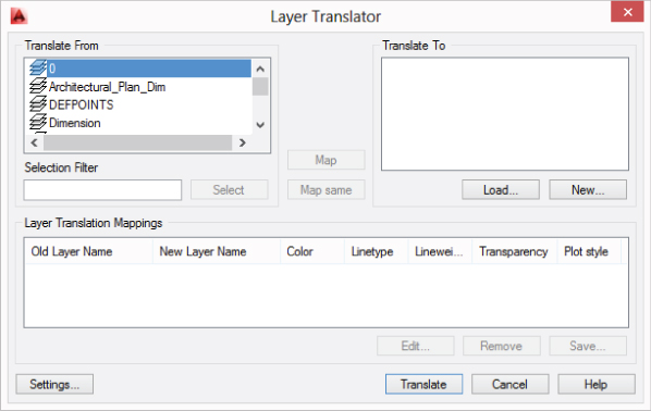
Figure 1.16 Defining a new layer to use as part of the layer translation map
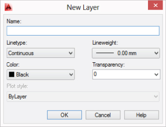
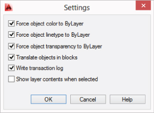
Figure 1.17 Changing the settings to use when translating layers
- If you clicked Translate And Save Mapping Information, the Save Layer Mappings dialog box is displayed. Browse to a location and enter a name for the file. If needed, choose Standards (*.dws) or Drawing (*.dwg) from the Files Of Type drop-down list, and then click Save. After the translation mappings are saved, the layers are updated in the current drawing according to the layer mappings you created.
- If you clicked Translate Only, the layers are updated in the current drawing based on the layer mappings you created and then the layer translation mappings are discarded.