
Chapter 4
Manipulating the Drawing Environment
The chapters until now have focused primarily on drawing-file customization: establishing and enforcing drawing standards, creating drawing templates, and working with named objects and blocks. While drawing-file customization should be used to form the cornerstone of your overall customization plans for the Autodesk® AutoCAD® program, there are limitations to the productivity gains that can be made with drawing-file customization only.
After you have established the drawing standards and template files that you will use to create new drawings, the next step in becoming more productive is to customize the AutoCAD drawing environment. The drawing environment controls the settings that are used to specify the behavior of commands, where AutoCAD looks for custom files, how the user interface looks, the behavior of the command prompt, and much more.
Getting Started with Drawing-Environment Customization
Although it might be new to you, customizing AutoCAD is something with which you should feel free to experiment. Before you start, I have a few words of advice:
- Back up the AutoCAD customizable files before making changes to them. In Windows, use the product's Export AutoCAD <release> Settings option on the Start menu or Start screen to create a backup of the custom settings and files for AutoCAD. You can then restore the exported settings using the Import AutoCAD <release> Settings option on the Start menu or Start screen. On Mac OS, you will need to copy the files under the Local and Roaming folders located under /Users/<user_name>/Library/Application Support/Autodesk on your local hard drive.
- Start small and test often. Too often I have seen people take on a customization project that is more than they are ready for and get frustrated, which has led them to just give up. You have to learn to walk before you can run. Also, make sure you do not customize lots of different files and features in AutoCAD without testing your changes; making too many changes at once could lead to some unnecessary troubleshooting that could have been avoided if additional testing was performed along the way.
- If you get stuck, take a deep breath and reset AutoCAD to its installed state. You will want to try and restore any files that you previously backed up before resetting AutoCAD, though. Even before resetting AutoCAD, make a copy of the current customized files. On Windows, use the product's Reset Settings To Default option on the Start menu or Start screen to reset the program's custom settings and files. On Mac OS, start AutoCAD and display the Application Preferences dialog box (options command). In the Application Preferences dialog box, on the Application tab click Reset Application Options and then click Reset AutoCAD.
Now that you are ready to get started, here are the ways the drawing environment can be customized that we'll discuss in this chapter:
- Command-line switches can be used in combination with desktop icons or batch and Bash shell files to control the way AutoCAD starts up.
- Preferences and settings that affect the way the application looks, where custom files can be located, and how some commands behave can be set and managed with the options command.
- System and environment variables can be queried and set from the command prompt to control the behavior of AutoCAD and many commands.
- Command aliases and external commands can be defined to allow quicker access to commands and system variables from the command prompt.
- Command-line input can be configured to control the way typed input is handled and the choices that are displayed in the command suggestion list.
Customizing the AutoCAD Startup Process
Before you start AutoCAD, you have an opportunity to specify which drawing to open and additional parameters known as command-line switches that can be used to control a number of different features at startup. Command-line switches must be placed after the acad.exe file in the Target field of a shortcut or batch file on Windows, or after AutoCAD in a Bash shell file on Mac OS.
The following shows an example of calling acad.exe on Windows using the /t command-line switch to create a new drawing based on a drawing template file named acad3D.dwt:
"C:Program FilesAutodeskAutoCAD 2014acad.exe" /t "acad3D.dwt"
The following shows an example of calling AutoCAD on Mac OS using the -t command-line switch to create a new drawing based on the acad3D.dwt drawing template file:
"/Applications/Autodesk/AutoCAD 2014/AutoCAD 2014.app/Contents/MacOS/AutoCAD" ↵
-t "acad3D.dwt"
AutoCAD on Windows supports 15 command-line switches, whereas AutoCAD on Mac OS supports only 5. You can use multiple command-line switches when starting AutoCAD: just add a space after a switch and the previous parameter. Table 4.1 lists the most commonly used command-line switches for Windows, as well as 3 of the 5 switches that are supported on Mac OS.
Table 4.1 AutoCAD command-line switches
| Switch Name(Windows) | Switch Name(Mac OS) | Description |
| /b | -b | Starts the script file after the specified or default drawing is opened at startup Usage: /b "script_name.scr" or -b "script_name.scr" |
| /nohardware | Disables hardware acceleration Usage: /nohardware |
|
| /nologo | -nologo | Hides the application's splash screen Usage: /nologo or -nologo |
| /p | Sets a user profile as current or imports a previously exported user profile Usage: /p "profile_name|profile.arg" |
|
| /t | -t | Creates a new drawing file based on the specified drawing template file Usage: /t "template_name.dwt" or -t "template_name.dwt" |
| /set | Loads a Sheet Set (DST) file Usage: /set "sheet_set_name.dst" |
|
| /w | Sets a workspace as current Usage: /w "workspace_name" |
On Windows, you can create a new desktop shortcut that starts AutoCAD and specifies the use of more than one switch. The example that follows uses the /t, /p, and /w command-line switches. Begin by copying the book's sample files from www.sybex.com/go/autocadcustomization to a folder named MyCustomFiles.
Figure 4.1 Setting the properties for the new shortcut
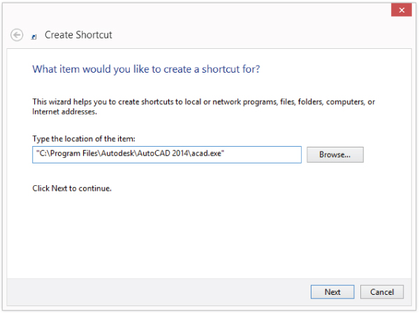
/t "%userprofile%/Documents/MyCustomFiles/C-Size.dwt" /p ↵
"<<Unnamed Profile>>" /w "AutoCAD Classic"
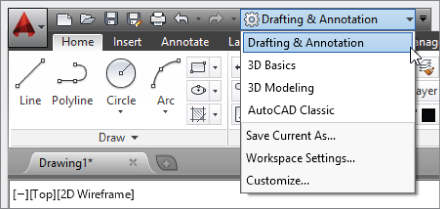
- From the Workspaces drop-down list on the Quick Access toolbar (see Figure 4.2), select the value of the wscurrent system variable that you wrote down in step 10.
- Right-click in the drawing window and click Options. In the Options dialog box, click the Profiles tab and then select the profile you wrote down in step 10. Click Set Current and then click OK to set the profile as current and exit the Options dialog box.
Figure 4.2 Switching workspaces
After you create a shortcut, you can edit the command-line switches that it uses. To edit a shortcut, right-click the shortcut and click Properties. When the Properties dialog box opens, click the Shortcut tab, and edit the text in the Target text box.
On a system running Mac OS, you can use the following steps to create a Bash shell file named acad-startup.sh that can be used to start AutoCAD and specify the use of the -nologo and -t command-line switches. Begin by copying the book's sample files from www.sybex.com/go/autocadcustomization to a folder named MyCustomFiles.
"/Applications/Autodesk/AutoCAD 2014/AutoCAD 2014.app/Contents/MacOS/ ↵
AutoCAD" -nologo -t ˜/Documents/MyCustomFiles/C-Size.dwt
Specifying Application Preferences
AutoCAD has evolved over the 30 or so years that it has been around, but the way users work with the software hasn't always followed suit. The AutoCAD on Windows settings have been organized into 12 categories to make it easy to locate a specific setting. (There are even more settings that are specific to AutoCAD-based vertical products.) AutoCAD on Mac groups its settings into 6 different categories. Many settings are available on both Windows and Mac OS, but there are many differences as well, because different features are supported on each platform.
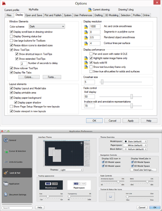
You configure the application preferences using the options command, which displays the Options dialog box on Windows and the Application Preferences dialog box on Mac OS. Figure 4.3 shows both of the dialog boxes. In the Windows Options dialog box, the tabs along the top allow you to switch between settings categories. The vertical tabs on the left of the Mac OS Application Preferences dialog box perform the same function.
Figure 4.3 Setting application preferences
You can display the Options or Application Preferences dialog box using one of the following methods:
- Click the Application menu button → Options (Windows).
- On the Mac OS menu bar, click AutoCAD <release> → Preferences (Mac OS).
- Secondary-click or right-click in the drawing window or over the command-line window, and then click Options (Windows) or Preferences (Mac OS).
- At the command prompt, type options and press Enter (Windows and Mac OS).
Both of these dialog boxes offer an extensive number of settings that can't all be covered in this book. Some of them are user-driven choices that do not impact the use of menu elements, creation and running of scripts, or creation and deployment of AutoLISP programs or other custom programs. Throughout this book when appropriate, I will mention the settings that you should be aware of because they could alter the way you deploy your customization and explain how your customization might be affected. You can click the Help button in the Options or Application Preferences dialog box to learn more about the settings on each tab.
One of the main differences between AutoCAD on Windows and AutoCAD on a Mac OS is in how you can manage application preferences. AutoCAD on Windows supports multiple user profiles, whereas AutoCAD on Mac OS supports only a single user profile. User profiles allow you to configure AutoCAD several different ways, and then switch back and forth between the settings that you might need to use based on the type (2D/3D) or discipline (civil, architectural, etc.) of the drawing you are working on.
The following example explains how to create a user profile named MyProfile in AutoCAD on Windows:

A profile must be set as current before AutoCAD can use the settings it was defined with. The next steps explain how to set as current the MyProfile profile that you just created:
User profiles can be shared with other users in your department or company. Use the following steps to export and then import the user profile MyProfile that you created earlier in this section:
Customizing the Elements in the Drawing Window
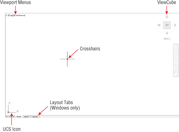
The drawing window used to create and edit the objects in an open drawing file can be customized to show different elements. Some of the elements in a drawing window (see Figure 4.4) are designed for when you work on 3D models and others for when you are working on 2D drawings.
Figure 4.4 Elements of the drawing window
The following elements can be customized using the options command to display the Options dialog box (Windows) or Application Preferences dialog box (Mac OS):
Crosshairs
The crosshairs provide you with a visual guide and an indicator of the location in the drawing window for the next point you pick. You can control the size of the crosshairs on the Display tab in the Options dialog box (Windows) or the Cursor & Selection tab in the Application Preferences dialog box (Mac OS). As an alternative to the dialog box, you can use the cursorsize system variable to change the size of the crosshairs. On Windows, you can also enable the display of the Z-axis and axes labels for the crosshairs on the 3D Modeling tab of the Options dialog box.
Viewport Menus
Viewport menus allow you to access named and preset viewport configurations, views, and visual styles. You can also control the display of the ViewCube®, SteeringWheels®, and Navigation Bar. You can toggle the display of the Viewport menus on the 3D Modeling tab in the Options dialog box (Windows) or the General tab in the Application Preferences dialog box (Mac OS). The vpcontrol system variable can also be used to toggle the display of the Viewport menus.
UCS Icon
The UCS icon shows the directions of the X-, Y-, and Z-axes in the current drawing. You can customize how the UCS icon looks using the Properties option of the ucsicon command. In addition to the appearance of the UCS icon, you can control if and where the UCS icon is displayed with the ucsicon command. The display of the UCS icon in a viewport with a 2D or 3D visual style can be controlled on the 3D Modeling tab in the Options dialog box (Windows) or the Look & Feel tab in the Application Preferences dialog box (Mac OS). As an alternative to using the dialog boxes, you can use the system variables that begin with ucs to control the behavior of the UCS icon as well as when it is displayed.
Layout Tabs (Windows Only)
Layout tabs allow you to switch between Model and any named layouts that are defined in the drawing. When the tabs are suppressed, a new button is added to the status bar. You can toggle the display of the Layout tabs on the Display tab in the Options dialog box.
ViewCube
The ViewCube allows you to rotate the current view of the drawing by clicking one of the predefined areas or dragging the cube. The ViewCube is designed primarily for those who work on 3D models, but it does have some functionality that those working on 2D drawings can take advantage of. You can control the behavior and size of the ViewCube with the Settings option of the navvcube command, which displays the ViewCube Settings dialog box. The display of the ViewCube in a viewport with a 2D or 3D visual style can be controlled on the 3D Modeling tab in the Options dialog box (Windows) or the Look & Feel tab in the Application Preferences dialog box (Mac OS). As an alternative to using the dialog boxes, you can use displayviewcubein2d and other system variables that start with navv to display and control most of the features of the ViewCube.
Element Colors
The colors for some of the elements in the drawing window are inherited from the operating system, but most of the colors used by elements in the drawing window are controlled by AutoCAD. The colors used by the drawing window can be controlled on the Display tab in the Options dialog box (Windows) or the Look & Feel tab in the Application Preferences dialog box (Mac OS). There is no alternative approach using system variables to manipulate the colors used in the drawing window, but you can use the ActiveX API with AutoLISP or VBA if you are using AutoCAD on Windows.
The changes made to these drawing-window elements are persisted between sessions as part of the AutoCAD user profile. AutoCAD for Mac does not support creating additional user profiles like AutoCAD on Windows does. For information on creating user profiles, see the “Specifying Application Preferences” section earlier in this chapter.
Configuring Command and Dynamic Input
An area of AutoCAD customization that is often overlooked is one that every user interacts with hundreds of times in a day—the command prompt. The command prompt is displayed in the command-line window and dynamic input features. When a command is not active, as you enter values at the command line or in a dynamic tooltip, you will see a suggested list of commands and system variables; the suggestions are based on the letters or numbers that you enter. You can customize the way you enter coordinate, angular, and distance values while a command is active and dynamic input is enabled.
Command Input Search Options
Starting with AutoCAD 2013, in Windows the Input Search Options dialog box (inputsearchoptions command) allows you to change the input settings for the command prompt (see Figure 4.5). In AutoCAD for Mac, use the -inputsearchoptions command; the Input Search options dialog box is not available. The -inputsearchoptions command is also available on Windows.
Figure 4.5 Customizing the input search options for the Command prompt
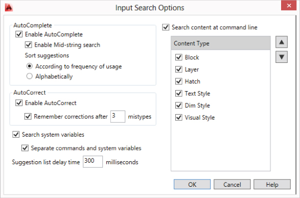
The command prompt features that you can control are as follows:
AutoComplete
Controls whether AutoCAD attempts to match the letters or numbers users enter at the command prompt against all of the registered commands and system variables. Because of the way matching is performed, you see a larger number of entries in the suggestion list than when the feature is disabled. If you are using AutoCAD on Windows, you can enable mid-string searching and control whether the suggestion list is sorted by usage or alphabetically.
AutoCorrect (AutoCAD 2014 on Windows Only)
Allows AutoCAD to monitor the way you input commands and system variables. Over time, if you enter the same incorrect name more than three times and choose the correct one from the suggestion list, AutoCAD creates a command alias for you based on the incorrect name and the command or system variable you meant to enter. For more information on how the AutoCorrect feature works, see the section “Adding Synonym and AutoCorrect Entries (Windows Only)” later in this chapter.
Search for System Variables
System variables are added to the suggestion list with commands. If you do not work with system variables all the time, disabling this feature can reduce the number of entries in the suggestion list for you. If you are using AutoCAD on Windows, you can separate commands and system variables in different areas of the suggestion list.
Suggestion-List Delay
You can specify the number of milliseconds between keystrokes that AutoCAD delays before displaying the suggestion list. If you are a fast typist or the command prompt doesn't seem to recognize the keystrokes you type, you might want to set this number higher than its default of 300. You can also change the delay value by using the inputsearchdelay system variable.
Search Content (AutoCAD 2014 on Windows Only)
Several of the named objects that can be created in a drawing can be set as current or used by entering the name of the object at the command prompt. If you do not set a named object as current or insert a block by typing its name at the command line, you might want to consider turning it off.
Command Input History
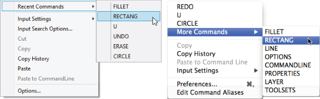
As input is entered at the command prompt, it is stored and can be recalled later. When a command is not active, you can access recently used commands; when a command is active, you can access recently entered coordinate input. The inputhistorymode system variable controls the type of input that is recorded and where it can be accessed from. Recent input can be accessed from the command line on both Windows and Mac OS (see Figure 4.6). On Windows systems, you can also access recent input from the drawing-window shortcut menu. Additionally, you can press the up- and down-arrow keys on the keyboard to cycle through recent commands and input.
Figure 4.6 Accessing recently used commands and coordinate values
You can also use the cmdinputhistorymax system variable to control the number of coordinate input entries that are recorded. If you reduce the value of the cmdinputhistorymax system variable, the changes might not be obvious until you restart the application, reopen any drawings that are currently open, or open another drawing.
Dynamic Input
Dynamic input displays prompts, tooltips, and pointer and dimension input fields at the cursor when the feature is enabled. The Dynamic Input tab of the Drafting Settings dialog box (dsettings command), as shown in Figure 4.7, allows you to customize the fields and tooltips used for dynamic input. You can also use the system variable dynmode to enable or disable dynamic input. On Windows, you can also control the display of the Z field of the pointer input field on the 3D Modeling tab in the Options dialog box (options command).
Figure 4.7 Controlling the behavior and appearance of dynamic input
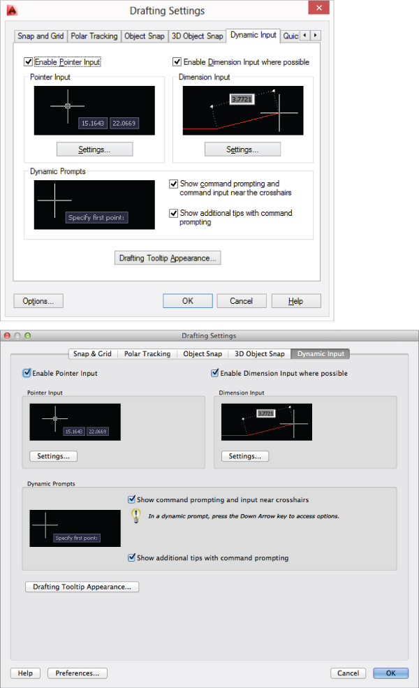
The following explains what each area of the Dynamic Input tab controls:
Pointer Input
Clear Enable Pointer Input to suppress the ability to enter coordinate values when prompted for a point by the current command. Click Settings to display the Pointer Input Settings dialog box and specify the coordinate format that should be applied when a command requests a second or next point. You can also control when the coordinate tooltips are displayed. The dynpicoords and dynpiformat system variables can be used to control the pointer input options at the command prompt.
Dimension Input
Clear Enable Dimension Input Where Possible to suppress the ability to enter distance and angular values based on the previous point when prompted for a second or next point by the current command or while using grips. Click Settings to display the Dimension Input Settings dialog box and control the number and type of dimension input fields to display when being requested for coordinate, distance, and angular values while a command is active. The dyndivis and dyndigrip system variables can be used to control the dimension input options at the command prompt.
Dynamic Prompts
The settings in this section control if the prompts and messages displayed near the crosshairs should be merged into a single tooltip or displayed as multiple tooltips. The dynprompt, dyninfotips, dyntooltips, and tooltipmerge system variables can be used to control the appearance of the dynamic input tooltips at the command prompt.
Drafting Tooltip Appearance
Clicking this button displays the Tooltip Appearance dialog box, which allows you to control the color, size, and transparency for dynamic input tooltips and fields.
Creating and Modifying Command Aliases
Command aliases allow you to quickly start a command or access a system variable by entering a few letters at the command prompt instead of entering its full name or locating it in the user interface. Don't confuse command aliases with keyboard shortcuts, which are key combinations that require you to press a combination of the Ctrl/Control, Shift, Alt/Option, or Command keys with a letter, number, or virtual key. I discuss more about creating custom shortcut keys in AutoCAD on Windows in Chapter 5, “Customizing the AutoCAD User Interface for Windows.”
AutoCAD comes with hundreds of predefined command aliases that are available for many of the most commonly used commands and system variables. You can save time performing everyday drafting tasks by learning the command aliases for the commands you use most frequently, since you do not need to move the cursor outside the drawing area to start a command.
Some of the commonly used command aliases are l for line, e for erase, and dli for dimlinear. If a command alias does not exist for the commands or system variables you commonly use, you can define new or override existing aliases by editing the acad.pgp file.
In addition to starting an AutoCAD command, command aliases can be used to start external applications from AutoCAD on Windows only. For example, you can launch Windows Explorer or File Explorer by using the alias explorer or start Notepad by entering notepad at the AutoCAD command prompt.
Defining Command Aliases
Command aliases are stored in the acad.pgp file, which is a plain ASCII text file that can be edited using Notepad on Windows or TextEdit on Mac OS. The acad.pgp file is divided into two sections: external commands and command aliases. I cover external commands in the section “Defining External Commands (Windows Only)” later in this chapter.
Two pieces of information are required to define a command alias: an abbreviation, which is the shortened command name (or alias) you want to use to start a command, and then the name of the AutoCAD command you want to start. A command alias can only start a command; it can't pass any values to the options of the command it starts. If you want to start a command and pass values to the options of the command that is started, you can use a script, action macro, or a custom command defined with AutoLISP. I discuss scripts and action macros in Chapter 8, “Automating Repetitive Tasks.”
A command alias has the following syntax:
<abbreviation>, *<command>
Table 4.2 lists some of the most commonly used command aliases and how they are defined in the acad.pgp file.
Table 4.2 Commonly used command aliases
| Abbreviation | Command |
| E, | *ERASE |
| C, | *CIRCLE |
| CO, | *COPY |
| DLI, | *DIMLINEAR |
| L, | *LINE |
| Z, | *ZOOM |
The acad.pgp file is loaded each time AutoCAD is started, when the reinit command is used, or when the re-init system variable is set to a value of 16. When the acad.pgp file is loaded, AutoCAD reads the file in a top-down order looking for command alias definitions. If AutoCAD encounters one or more command aliases with the same abbreviations, it remembers only the last command alias it read as it follows the “last one in wins” rule.
Since the acad.pgp file allows you to define more than one command alias with the same abbreviation and AutoCAD uses the “last one in wins” rule when loading command aliases, Autodesk recommends that you place all your custom command aliases under the User Defined Command Aliases section of the acad.pgp file. The User Defined Command Aliases section is located at the bottom of the acad.pgp file.
The following example explains how to define a new command alias and redefine two of the standard command aliases that come with AutoCAD:
- On the ribbon, click Manage tab → Customization panel → Edit Aliases drop-down menu → Edit Aliases (Windows).
- At the command prompt, type ai_editcustfile and press Enter. At the Custom File to edit: prompt, type acad.pgp and press Enter (Windows).
- Click Tools menu → Customize → Edit Command Aliases (PGP) (Mac OS).
- At the command prompt, type aliasedit and press Enter (Mac OS).
REV, *REVCLOUD
L, *PLINE
JU, *JUSTIFYTEXT
Defining External Commands (Windows Only)
External commands are stored in the acad.pgp file, just like command aliases are, but they are only supported in AutoCAD on Windows.
External commands use the following syntax:
<abbreviation>,[<shell_call>],<flag>,[*]<prompt>,
abbreviation
The name that you enter at the command prompt to start the external application.
shell_call
Specifies which command to use from the MS-DOS or Windows command prompt. Some examples of commands that you can use are START, which allows you to launch an application, DEL to delete a file, or TYPE to display the contents of a file.
flag
Controls how the application is called. The available values can be found in the acad.pgp file by searching on the text External command format.
prompt
Specifies an instructional message to the user at the AutoCAD command prompt, and requests input from the user that can be passed to the command in the shell_call argument.
The following shows a couple of the external commands that are predefined in the acad.pgp file:
DEL,      DEL,            8,File to delete: ,
NOTEPAD,  START NOTEPAD,  1,*File to edit: ,
The following steps explain how to define a new external command to start the Windows Calculator (calc.exe):
- On the ribbon, click Manage tab → Customization panel → Edit Aliases drop-down menu → Edit Aliases.
- At the command prompt, type ai_editcustfile and press Enter. At the Custom File to edit: prompt, type acad.pgp and press Enter.
CALC, START CALC, 1,,
Adding Synonym and AutoCorrect Entries (Windows Only)
Starting with AutoCAD 2014, two new command alias–related features were introduced. These features are known as synonyms and AutoCorrect, and they are available in AutoCAD on Windows only. Synonym and AutoCorrect entries are stored in the acadSynonymsGlobalDB.pgp and AutoCorrectUserDB.pgp files, respectively, and follow the same syntax as the command aliases I mentioned in the section “Defining Command Aliases” earlier in this chapter.
Synonym entries allow you to provide a natural name or term as an alternative to an AutoCAD command; this should not be a shortened name, though, like the command aliases in the acad.pgp file. For example, you might commonly use the term symbol at your company or in your industry as opposed to block. AutoCAD does not have a symbol command, so in previous releases you had to learn both the AutoCAD lingo and its commands. Now with synonyms, it is much easier to enter some industry terms like symbol or callout at the AutoCAD command prompt and start an associated command. You can add your own or change existing synonyms in the acadSynonymsGlobalDB.pgp file using Notepad.
The following example explains how to add a synonym entry for the term bevel and have it start the chamfer command. For more information on defining command aliases and reloading PGP files, see the “Defining Command Aliases” section.
BEVEL, *CHAMFER
AutoCorrect entries share the same syntax as synonyms and command aliases, but you typically do not add new entries to the AutoCorrectUserDB.pgp file directly using Notepad. Instead, AutoCorrect entries are added automatically as a result of incorrectly entering the name of a command or system variable and then choosing the correct spelling from the suggestions list.
You must misspell a name and select the correct one three times before the term will be added to the AutoCorrectUserDB.pgp file. You enable the AutoCorrect feature and the number of times a correction must be made before an entry is added to the PGP file by using the Input Search Options dialog box (inputsearchoptions command); see Figure 4.5 earlier.
The following steps explain how to check if AutoCorrect is enabled, and if it isn't, how to enable it:
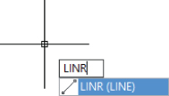
You can add an AutoCorrect entry from the AutoCAD user interface for a misspelling of the line command by performing the following steps:
Figure 4.8 Command suggestion list based on typed characters
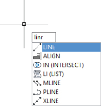
Figure 4.9 AutoCorrect entry in the command suggestion list
Working with System and Environment Variables
Commands and dialog boxes are used to create, modify, and manage drawing objects and application settings. When most commands or dialog boxes are used, they store and access settings that might be held temporally in memory or persist within individual drawing files across application sessions. Some of these settings are exposed for users and developers to gain a level of control over AutoCAD; the exposed settings are known as system and environment variables.
System and environment variables can be accessed from the command prompt or through supported programming languages. Of the two variable types, system variables are the most common. Both types of variables can store values that represent a string, number, coordinate point, lists of values, and much more. You can query and set the value of a system variable with the setvar command, or with the getvar and setvar AutoLISP functions. Environment variables can be queried and set using the getenv and setenv AutoLISP functions. There is no equivalent to the setvar command that allows you to directly access and set the value of an environment variable.
You can learn more about accessing system and environment variables with AutoLISP and VBA from the AutoCAD Help system. If you are using Managed .NET and C++ with ObjectARX®, you will want to use the documentation that comes with the ObjectARX SDK to learn how to access system and environment variables.
Listing and Editing System Variables
The setvar command allows you to list all supported system variables and their current values. The following explains how to obtain a listing of all supported system variables:
The system-variable list displayed by the setvar command contains the name, current value, and read-only state of each variable listed. You can access additional information about a system variable from the product's Help system.
3DCONVERSIONMODE 1
3DDWFPREC        2
APBOX            0
APERTURE         10
Press ENTER to continue:
Use the following steps to access help for a system variable (or command) from the command prompt. These specific steps explain how to access help for the dimtp system variable:
You can change the value of a system variable by entering its name directly at the command prompt or at the Enter variable name or [?]: prompt of the setvar command. Follow these steps to change the value of the dynmode system variable, which enables the use of dynamic input:
When you assign a value to a system variable, the value you are assigning must be of the correct data type. For example, the dynmode system variable expects an integer and if passed a string of "3" instead of 3, an error message is displayed and the command ends. The same happens if you enter an unexpected value. Refer to the Help topic that covers the system variable for information about the type of data and the values that the system variable expects.
Listing and Editing Environment Variables
Environment variables are kind of a mystery at times since they are not really documented, so in many ways they must be discovered. A few of them can be found in the AutoCAD product documentation, but the best option is to use your favorite search engine and see what other users have found. I do not have a great understanding as to why they are not documented like system variables.
Even though they are not commonly used, there are three environment variables you might need to change or query from time to time based on your drawing requirements:
MaxArray
Specifies the maximum number of objects that can be created during a single use of the ARRAY command.
MaxHatch
Specifies the maximum number of objects that can be displayed within a single hatch object. If you see the message Hatch Pattern Too Dense, you will need to increase the number of objects that can be displayed for hatch objects. If the limit is exceeded, the hatch object appears as a single fill. You might need to close and reopen a drawing for the new setting to be applied.
ACAD
Specifies the paths listed under the Support File Search Path of the Files tab in the Options dialog box on Windows or Application tab in the Application Preferences dialog box on Mac OS.
When you want to query or set the value of an environment variable, you need to use the getenv and setenv AutoLISP functions. The name of the variable is case specific, so MaxArray—not MAXARRAY or maxarray— must be provided to the functions. Also, when setting the value of an environment variable you must provide it as a string. In the following steps, you return and set the value of the MaxHatch environment variable:
(setq mh (getenv "MaxHatch"))
When you press Enter, the value of the environment variable is returned as a string to the command-line window.
(setenv "MaxHatch" "1000")
When you press Enter, the new value is repeated in the command-line window.
(setenv "MaxHatch" mh)
When you press Enter, the previous value is restored.