
Chapter 5
Customizing the AutoCAD User Interface for Windows
The Autodesk® AutoCAD® user interface provides you with one of the best opportunities to increase your productivity without learning a programming language. Many of the user-interface elements that allow you to start a command or toggle a system variable with a click of a button or the press of a key can be customized. By customizing the user interface, you can reorganize it to better fit the way you work, add the commands that you frequently use, and even remove those commands that you do not use.
You customize the user interface through a combination of direct manipulation and the Customize User Interface Editor—or CUI Editor, as it is commonly known. Direct manipulation can make it fast and easy to reorganize elements, but there are limitations, as not all elements are supported and new user-interface elements can't be added. The CUI Editor provides the most control over the elements of the user interface.
As you make changes to the user interface, the changes are stored as part of the Windows Registry or in the main customization (CUIx) file. CUIx files contain the definitions for many of the elements that are displayed in the AutoCAD application window, such as the buttons on a ribbon panel, items on the menu bar, or even shortcut key combinations.
Getting Started with the CUI Editor
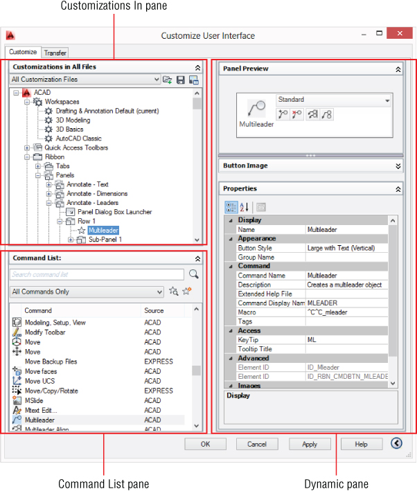
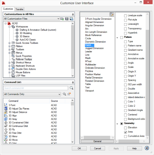
The CUI Editor is the tool that you will need to become familiar with to customize the AutoCAD user interface. Figure 5.1 shows the CUI Editor and highlights some of the areas that I will discuss. The editor might appear a bit overwhelming at first—and to be honest it can be because of everything it does—but there is nothing to be afraid of; I will guide you one step at a time. The CUI Editor is a much better solution for those new to customizing the AutoCAD user interface than what was available in the releases prior to AutoCAD 2006. In those versions, a dialog box offered only limited customization options. You needed to use an ASCII text editor like Notepad to customize all available elements.
Figure 5.1 The CUI Editor lets you create and modify user-interface elements.
Not that I have anything against Notepad; it just does not know what needs to be done to create a toolbar, add a toolbar button, or define a pull-down menu with a series of items. If you forget a character, attempting to load the miscoded menu/customization file often results in a cryptic message from AutoCAD. The CUI Editor lowers the learning curve for creating and modifying user-interface elements.
You can display the CUI Editor using one of the following methods:

- On the ribbon, click Manage tab → Customization panel → User Interface.
- Right-click a button on the Quick Access toolbar or a standard toolbar and click Customize Quick Access Toolbar or Customize, respectively.
- At the command prompt, type cui and press Enter.
When the CUI Editor is displayed, notice that there are two tabs. Each tab is divided into areas called panes. The two tabs in the CUI Editor and their purpose are as follows:
Customize Tab
Use the Customize tab to create, modify, and organize the user-interface elements that come with AutoCAD or those that you create. You will also use this tab to create workspaces that allow you to control when and where specific user-interface elements are displayed. This tab is divided into three panes:
Customizations In Pane
Here you will find a listing of the CUIx files that are currently loaded and the user-interface elements that they contain. When a user-interface element is expanded, you see each of the items that make up that particular element, such as the buttons on a ribbon panel or the items on a pull-down menu. When you select a user-interface element, command, or control in this pane, its properties can be changed in the Dynamic pane.
Command List Pane
Here you'll find a list of the commands and controls that you can add to the user-interface elements in the Customizations In pane. New custom commands for use in the user-interface are created in this pane. Selecting a command from this pane displays its properties in the Dynamic pane, where you can change the image, name, macro, and other settings that define how a command appears in the user interface.
Dynamic Pane
Displays the properties of an item selected from either the Customizations In or Command List pane. Based on the item selected, one or more of eight different subpanes could be displayed. I cover each of these panes later in this chapter as I explain how to customize the elements of the user interface.
Transfer Tab
Use the Transfer tab to copy user-interface elements between customization (CUIx) files, migrate user-interface elements from an earlier release, and create new or save existing CUIx files.
Creating Commands and Defining Command Macros
Commands are the primary component of elements in the AutoCAD user interface, and they are created in the Command List pane of the CUI Editor. The properties of a command in a CUIx file define the sequence of AutoCAD commands and options that will be executed when the command is used, and how the command should appear on a user-interface element. The sequence of AutoCAD commands and options that are assigned to a command are contained in a macro. The macro is the most significant property of a command in a CUIx file.
Understanding the Basics of a Command Macro
A macro defines the input that is sent to the AutoCAD command prompt when a user-interface element is used; it can, but does not necessarily need to, start and complete a command in a single command macro. You could start a command with one macro and then click another button to send an expected value to the active command. An example might be where one macro starts a custom AutoLISP® routine that prompts you for a bolt or window size, and rather than typing a size each time, you use a second macro to pass a value to the routine.
For the most part, a macro is similar to the input that you enter at the command prompt to start and complete an AutoCAD command, but it can also contain special characters that control its execution. For example, the following might be what you normally would do to draw a circle with a diameter of one-eighth of an inch:
An example of a command macro using the same input as the previous example might look something like this:
^C^C._circle;\_d;0.125;
As you can see, I used five special characters in the example macro that were not present as part of the original input entered at the command prompt: ^ (caret), . (period), _ (underscore), ; (semicolon), and (backslash). Table 5.1 explains the significance of each macro component.
Table 5.1 Meaning of macro components
| Macro Component | Description |
| ^C^C | Simulates the pressing of the Esc key twice. |
| ._circle | Passes the circle command to the command prompt. |
| ; | Simulates the pressing of the Enter key to start the circle command. |
| Pauses for the user to specify the center point of the circle. | |
| _d | Indicates that the Diameter option of the circle command will be used. |
| ; | Simulates the pressing of the Enter key to accept the Diameter option. |
| 0.125 | Specifies the value for the Diameter option. |
| ; | Simulates the pressing of the Enter key to accept the diameter value. Since this is the last expected value, the circle command ends too. |
Table 5.2 lists the most common special characters used in a command macro.
Table 5.2 Special characters that can be used in macros
| Special Character | Description |
| ^C | Equivalent to pressing Esc. |
| ; | Equivalent to pressing Enter. |
| [blank space] | Equivalent to pressing Enter or spacebar based on the expected input of the current prompt. |
| Allows the user to provide input. | |
| . | Instructs AutoCAD to use the command's standard definition even when a command might have been undefined with the undefine command. |
| _ | Instructs AutoCAD to use the global command name or option value instead of the local name or value provided. This allows the macro to function as expected when used with a different language of the AutoCAD release. |
| * | Repeats the AutoCAD command after the asterisk character until the user cancels the command. Example macro from the Point, Multiple Point command in the acad.cuix file: *^C^C_point |
| $M= | Indicates the start of a DIESEL expression. Example expression from the UCS Icon, On command in the acad.cuix file: $M=$(if,$(and,$(getvar,ucsicon),1),^C^C_ucsicon _off,^C^C_ucsicon _on) |
When combining multiple commands into a single menu macro, you will want to first step through the sequence at the command prompt. Doing this can help you identify which commands, options, and values you want to use. The following example demonstrates the commands and options you might use to create and set as current a layer named Notes and then draw a multiline text object:
After you've worked through the process at the command prompt, you can use that information to convert the process to a macro. The next steps walk you through the process of converting input entered at the command prompt into a command macro:
Figure 5.2 Command-line history of the input you previously entered
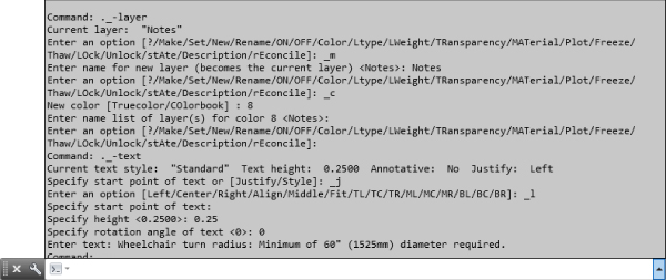
-layer;
m;
Notes;
c;
8;
;
;
-mtext;

j;
tl;
h;
0.25;
r;
0;
w;
7.5;
NOTE: ADA requires a minimum turn radius of;
60″ (1525mm) diameter for wheelchairs.;
;
^C^C-layer;m;Notes;c;8;;;-mtext;j;tl;h;0.25;r;0;w;7.5;
NOTE: ADA requires a minimum turn radius of;60″ (1525mm) for wheelchairs.;;
^C^C._-layer;_m;Notes;_c;8;;;._-mtext;\_j;_tl;_h;0.25;_r;0;_w;7.5;
NOTE: ADA requires a minimum turn radius of;60″ (1525mm) for wheelchairs.;;
Creating and Modifying Commands
Before you can use your macro, you first need to learn how to create a new command in a CUIx file. Commands are created under the Command List pane of the CUI Editor. You can also locate and modify existing commands in the CUIx files that are currently loaded.
The following example explains how to create a command for the macro that you created in the previous section in a current CUIx file. If you did not complete the steps for the previous example, you can open the NoteMacro.txt exercise file that is available for download from www.sybex.com/go/autocadcustomization. If you did complete the previous example but closed Notepad, launch Notepad and open the file MyNoteMacro.txt from the MyCustomFiles subfolder under the Documents (or My Documents) folder, or the location you used.
Figure 5.3 Defining the properties of a command
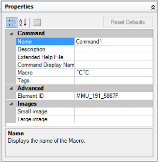
Figure 5.4 The properties of the completed command
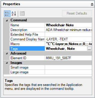
A command can be edited by selecting it from the Command List pane and then making changes to it in the Properties pane, just as you did when you created the new command.
Creating and Assigning an Image to a Command
While using images with your commands is optional, you should consider adding an image to each of the commands that you create in a CUIx file to provide the most flexibility. Although not all user-interface elements display an image, most of the common user-interface elements do. AutoCAD provides a basic image editor that allows you to create images for your commands right inside the CUI Editor. However, if you or someone else in your company has experience with a different image editor, you can use that software.
Here are the basic requirements your images need to meet:
- Small images should be 16×16 pixels in size.
- Large images should be 32×32 pixels in size.
- Images need to be in the BMP file format.
If an image is created using the Button Editor inside the CUI Editor, that image is saved as part of the CUIx file. You can export an image file if you want to edit the image outside of AutoCAD. You also can import into a CUIx file images that you created or edited outside of AutoCAD and then assign those images to a command. An alternative to importing images into the CUIx file is to create a resource DLL file that has the same name as the CUIx file being loaded into AutoCAD. This method is more common with third-party utilities that use CUIx files for their user-interface elements.
The following example explains how to create a custom image for the Wheelchair Note command you created in the previous section:
Figure 5.5 Creating a custom image
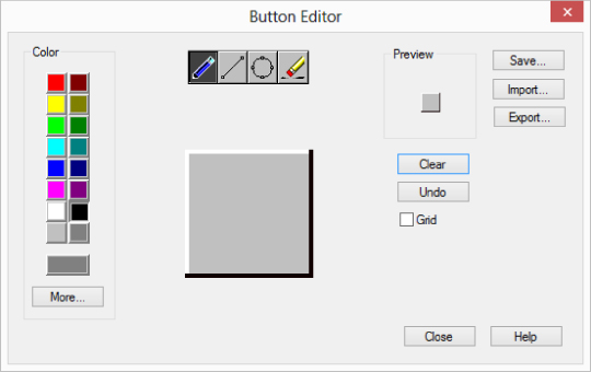
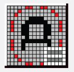
Figure 5.6 Example custom image
If you have an externally saved file that you want to use for a command, you can do the following:
![]()
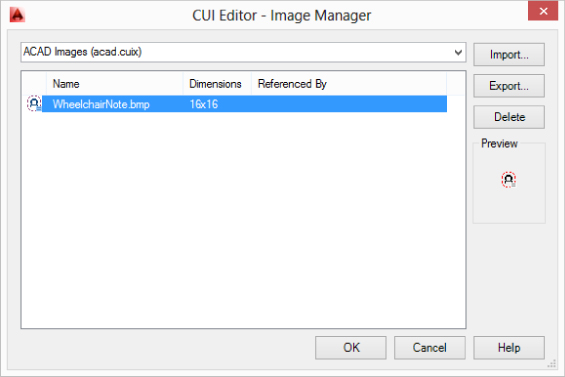
As I mentioned earlier, the images used for your commands are stored in the CUIx file. You can manage the images stored in a CUIx file using the CUI Editor - Image Manager (see Figure 5.7). Click the Image Manager button in the Customizations In pane to display the CUI Editor - Image Manager. Here you can perform the following tasks:
- View the images and their sizes
- Import externally stored BMP files
- Export selected images in the CUIx file and save them as individual BMP files
- Remove the images that you are not currently using
Figure 5.7 Managing images in the loaded CUIx files
Customizing User-Interface Elements
Out of the box, the AutoCAD user interface is designed for everyone, but not to accommodate the needs of any specific industry or any one single company's workflow. Many of the common user-interface elements in the AutoCAD application window can be customized, and you should take the time to customize them to get the most out of AutoCAD. You can add new elements that execute command macros and custom applications you create, remove or hide those that you do not use, or reorganize those that you use frequently to make them easier to access. You use the CUI Editor to modify the elements defined in a CUIx file.
The following elements of the user interface can be edited with the CUI Editor:
- Quick Access toolbar (QAT)
- Ribbon; panels and tabs
- Pull-down and shortcut menus
- Toolbars
- Double-click actions
- Shortcut and temporary override keys
- Mouse buttons
- Properties displayed as part of the Quick Properties palette or rollover tooltips
- Legacy elements; tablet menus and buttons; image tile and screen menus
Quick Access Toolbar
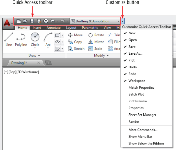
The Quick Access toolbar (QAT), shown in Figure 5.8, is part of the AutoCAD title bar area along the top of the application window. The tools commonly placed in the toolbar are for managing drawing files, plotting or publishing layouts, undoing or redoing recent actions, and setting a workspace current that is defined in the main CUIx file.
Figure 5.8 Accessing the customization options for the Quick Access toolbar
You can customize the QAT using one of the following methods:
QAT Customize Menu
Clicking the Customize button on the far right side of the QAT displays the Customize menu. From this menu, you can toggle the display of several additional select commands, click More Commands to display the CUI Editor, or click Show Below/Above The Ribbon to change the placement of the QAT.
QAT Shortcut Menu
Right-clicking a command or control on the QAT displays a shortcut menu that allows you to remove the element below the cursor, add a vertical separator bar to the right of the element under the cursor, click Customize Quick Access Toolbar to display the CUI Editor, or click Show Quick Access Toolbar Below/Above The Ribbon to change its placement.
Ribbon Button
Right-clicking a command on the ribbon displays a shortcut that contains the Add To Quick Access Toolbar item. This item adds the command to the QAT.
CUI Editor
The CUI Editor provides you with the same functionality that is found on the QAT's Customize and shortcut menus, and a few additional options as well. With the CUI Editor, you can choose to customize the default QAT or create a new one, and you can also change the order in which commands and controls are displayed.
Customizing the Default QAT
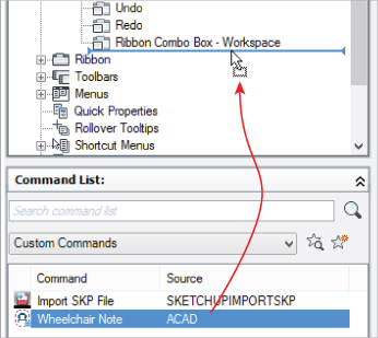
The next example explains how to customize the default QAT. You will add the Wheelchair Note command that you created earlier in this chapter.
Figure 5.9 Adding a command to the QAT
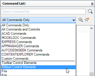
Now that the Wheelchair Note command has been added, let's add a separator and Layer controls to the QAT that we are customizing in this exercise:
Figure 5.10 Accessing the controls that can be placed on the QAT
There will be times when you want to remove access to particular commands. The next steps in this exercise explain how to remove the SaveAs command from the QAT and how to test the customized QAT:
Figure 5.11 Results of the customization to the QAT
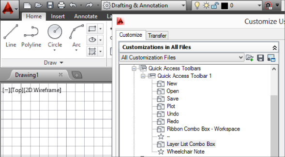
Figure 5.12 Tooltip for the custom Wheelchair Note command
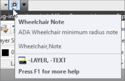
Figure 5.13 The results of using the Wheelchair Note command

Creating a New QAT
While AutoCAD can display only a single QAT at a time, you could create your own QAT that contains the commands and controls you want to use instead of modifying the default toolbar that is defined in the acad.cuix file. Not only could you create your own new QAT, but you could define multiple QATs that contain different commands and controls for each department in your company or for each discipline of drawings that you work on. If you create a new QAT, you must assign it to a workspace to display it in the user interface.
These steps explain the overall process for creating a new QAT and displaying it within a workspace:
Ribbon
The main AutoCAD user-interface feature that you most likely have interacted with is the ribbon. The ribbon follows Microsoft's design concept called “fluent user interface” (or FUI) and is similar in concept to the one found in the Microsoft Office products. The idea behind the design is that it makes it easier to discover and access the commands and options that a user is looking for with a rich visual user experience.
Pull-down menus and toolbars, which most applications still use to this day, provide a tried-and-true user experience, but they work best with a somewhat limited selection of commands. Pull-down menus and toolbars can handle hundreds of commands, but these elements lack the ability to start an operation and then give you additional choices while the operation is active.
Sure, you could show and hide menus and toolbars dynamically, but that introduces an element of inconsistency in the design. Where those items might appear this or next time becomes unpredictable. Dialog boxes are also a great way to allow the user to control the way a command or control might function, but that does not mean a user will always discover the most helpful settings. Instead of hiding useful settings and options, the design of the ribbon makes it easier to place them adjacent to a command or on a contextual tab. There is no doubt that the ribbon introduces an initial learning curve, but what doesn't when you are new to using it or after something you have done for a decade or two changes?
Commands and controls on the ribbon are organized by task through the use of tabs and panels, as shown in Figure 5.14. Each task is represented by a tab, which can hold different panels. A ribbon tab can be static—displayed all the time—or contextual, which means the tab is displayed only when a specific condition is met. If you have created a hatch or multiline text object in AutoCAD, chances are you worked with the Hatch Creation and Text Editor tabs that are displayed while you were using the hatch and mtext commands. Those tabs are contextual and are available only while the commands are active; ending the commands hides the tabs once again.
Figure 5.14 Command and control organization using the ribbon
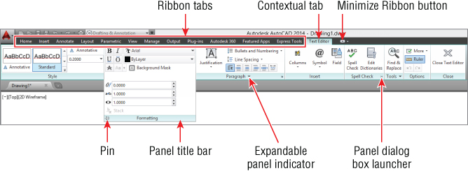
The ribbon is divided into panels, which are used to organize and display commands and controls to the user. Panels have two different display states: normal and expanded. Not all panels are configured to be expanded, but when a panel offers additional commands or controls that are not displayed by default, you see a down arrow to the right of the ribbon's title. Clicking the panel's title bar expands the panel.
When a panel is expanded, it can be pinned (forced to remain expanded until you switch tabs or unpin it) using the Pin button, shown in Figure 5.14. Some panels show a panel dialog-box launcher button, also shown in Figure 5.14, which can start a command that commonly displays a dialog box or palette that is related to the commands and controls on the ribbon panel.
When customizing the ribbon, you can control the display of ribbon tabs with a workspace. Workspaces are also used to control the order in which tabs appear on the ribbon in the user interface. For more information on workspaces, see the section “Organizing the User Interface with Workspaces” later in this chapter. From the AutoCAD application window, you can also show and hide ribbon panels and tabs by right-clicking a panel or tab on the ribbon. Then, from the shortcut menu, click the element you want to show or hide. You can also modify the order in which ribbon panels and tabs are displayed by clicking and dragging an element on the ribbon.
Ribbon Panels
Ribbon panels are containers for the commands and controls that you eventually want to display on the ribbon. Each ribbon panel is divided into two areas; the upper area is always displayed, and the lower area is displayed only when the panel is expanded by clicking a panel title bar. The lower area is known as the slideout.
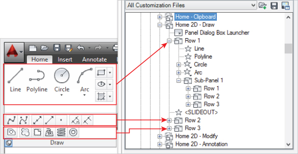
The commands and controls on a panel must be placed in a row. A panel can contain more than one row, but a panel must always have at least one row in order to contain commands or controls. A row can be divided into one or more rows with the use of a subpanel. A row can also contain a Fold panel, which can contain commands and controls as well. A fold panel differs from a subpanel in that it can't contain any rows; however, it can be assigned a collapse priority and resizing considerations. Separators and drop-down menus allow you to further organize related commands and controls on the panel. Figure 5.15 shows the Draw panel on the ribbon and how it is defined in the CUI Editor using rows and a single subpanel.
Figure 5.15 Structure of the Home 2D - Draw panel
The following example explains how to create a new panel named My Tools:
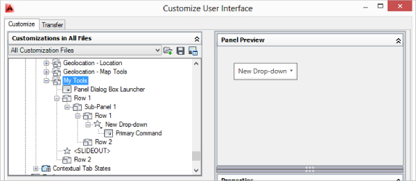
Now, let's add structure to organize commands and controls:
Figure 5.16 Structure for the new My Tools panel
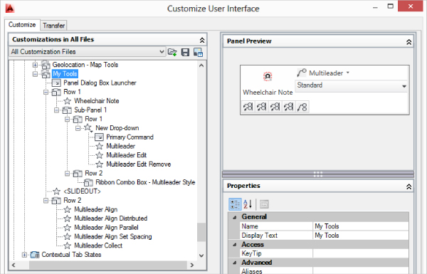
The next steps explain how to add commands and controls to the rows of the ribbon panel:
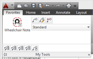
Figure 5.17 The completed My Tools panel
Once you have created a panel, you must add it to a tab in order for it to be displayed on the ribbon. I cover customizing ribbon tabs in the next section. You can modify an existing panel by selecting it from the Panels node under the Ribbons node of the Customizations In pane. The process for modifying a panel is similar to the process you used when you created the My Tools panel.
Ribbon Tabs
Ribbon tabs are used to control the display and organization of ribbon panels in the user interface. You can add and remove ribbon panels to or from one of the standard ribbon tabs or create your own. Often, if you create your own panels you will want to create your own ribbon tabs as well. Several conditions determine whether a tab displays in the user interface:
- Is the tab part of the current workspace?
- Is the tab enabled?
- Has the tab been assigned to a contextual state?
- Has a contextual condition been met?
Creating a New Ribbon Tab
The following example explains how to create a new tab named Favorites and how to add several ribbon panels to the new tab:
Figure 5.18 Favorites tab with the My Tools panel
Displaying Ribbon Tabs
After a ribbon tab has been created, you have two options for displaying it in the user interface:
- Add the ribbon tab to a workspace
- Add the ribbon tab to a contextual tab state
When you choose to add it to a workspace, you can control the location in which the tab appears on the ribbon and its default display state: shown or hidden. If you add the tab to a contextual tab state, you can control the tab's display type: full or merged.
Use the following steps to add the Favorites tab to the ribbon for the current workspace:
Figure 5.19 Customizing the current workspace
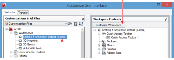
Figure 5.20 Adding the ribbon tab to the current workspace
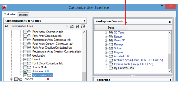
Figure 5.21 Controlling the order of the ribbon tab with the workspace
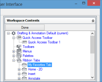
Figure 5.22 The Favorites tab displayed on the ribbon
Any ribbon tab can be added to a contextual tab, but typically the scope of the commands and controls on the panels of the tab are limited to editing objects only. Contextual tab states are not workspace specific, so there is no need to add contextual tabs to a current workspace.
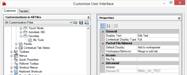
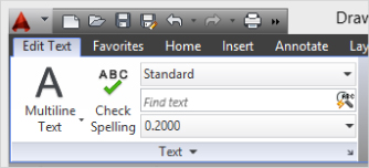
The following example explains how to create a new ribbon tab that contains the Annotate - Text panel, and adds the new ribbon tab to the Text, Multiline Selected contextual tab state.
Figure 5.23 The custom Edit Text tab displayed when the multiline text object was selected
Pull-Down Menus
The menu bar is an area commonly found along the top of an application window. It contains a number of menus, which are also referred to as pull-down menus. You click a label on the menu bar to display the associated pull-down menu. When displayed, you can click one of the items on the pull-down menu to start a command. A pull-down menu can contain separators and submenus to group related commands together.
The menu bar and pull-down menus were the primary method for accessing commands before the introduction of the ribbon. They are still used for corporate customization and are displayed by default with the AutoCAD Classic workspace. It is possible to display both the ribbon and menu bar. When the menubar system variable is set to 1, the menu bar is displayed just below the title bar of the AutoCAD application window.
Like the QAT and ribbon, you can customize the pull-down menus that come with AutoCAD or create your own. Pull-down menus can contain the commands that can be added to other user-interface elements but can't contain a drop-down list, check box, text box, or other common Windows controls that can be found on the ribbon or some toolbars. You can, however, use DIESEL to enable, disable, and/or display a check mark next to a menu item. For information on DIESEL and how to use it, refer to the AutoCAD Help system.
As you have seen with other user-interface elements, workspaces are also used to control the display of a pull-down menu on the menu bar and in which order all pull-down menus should be displayed. For more information on workspaces, see the “Organizing the User Interface with Workspaces” section later in this chapter.
The following explains how to create a new pull-down menu, add commands, and organize the commands with a separator and submenu:
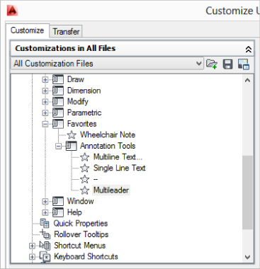
Figure 5.24 Structure of the Favorites pull-down menu in the CUI Editor
While a new pull-down menu is added to all the workspaces currently defined in the main customization (CUIx) file, you will want to make changes to each workspace to ensure the pull-down menu is in the correct position on the menu bar.
Use the following steps to add the pull-down menu if it is not displayed in the current workspace. I will also show you how to change the menu's position.
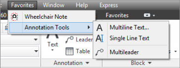
Figure 5.25 Favorites pull-down menu on the menu bar
Shortcut Menus
Shortcut menus make it easy to access the commands that you need when you need them—and near the cursor, so you don't have to leave the drawing area. You display a shortcut menu by right-clicking or secondary-clicking on the input device. The commands that you can access from a shortcut menu are often determined by the context in which the menu is displayed, which is why shortcut menus are sometimes referred to as context or contextual menus. Table 5.3 lists the shortcut menus that you can customize and the contexts in which they are displayed.
Table 5.3 Customizable shortcut menus
| Context | Description |
| Hot Grip | Displayed when a grip has been selected and is ready for editing, and you right-click in the drawing area |
| Object Snap | Displayed when the Shift key is held and you right-click in the drawing area |
| Default Mode | Displayed when no command is active, an object is selected, grip editing is not active, and you right-click in the drawing area |
| Command Mode | Displayed when a command is active and you right-click in the drawing area |
| Edit Mode | Displayed when an object is selected and you right-click in the drawing area |
Shortcut menus are customized with the CUI Editor using techniques that are nearly identical to those used for customizing pull-down menus. You add commands to the shortcut menu and use separators and submenus to organize related commands. Shortcut menus are not displayed as part of the main user interface, but are called on based on the current context. AutoCAD uses a special property value called an alias to determine which shortcut menu should be displayed. Each alias must be unique inside a customization (CUIx) file.
Table 5.4 lists the unique aliases and alias naming conventions that AutoCAD uses for displaying specific shortcut menus.
Table 5.4 Aliases and alias naming conventions for shortcut menus
| Alias | Description |
| GRIPS | Hot Grip Cursor menu |
| SNAP,POP0 | Object Snap Cursor menu |
| CMDEFAULT | Default Mode menu |
| CMCOMMAND | Command Mode menu |
| CMEDIT | Edit Mode menu |
| COMMAND_cmdname | Command-specific menu; cmdname represents the name of the command that the shortcut menu should be associated with. |
| OBJECT_objectname or OBJECTS_objectname |
Single or multiple selected objects menu; objectname represents the type of the object that the shortcut menu should be associated with. |
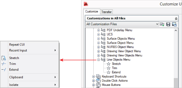
The next example explains how to create a new object shortcut menu that adds items to the Edit Mode menu when a line is selected:
Figure 5.26 Line Objects Menu in the drawing window
Command Mode Shortcut Menus
Command-specific menus insert additional items into the shortcut menu with the CMCOMMAND alias. You use the COMMAND_cmdname alias to specify which command the shortcut menu should be associated with. cmdname must match the name of a command defined with ObjectARX® or Managed .NET, not one that has been defined with AutoLISP. For example, to associate items with the LINE command's shortcut menu you would create a shortcut menu with the alias COMMAND_LINE.
Object Mode Shortcut Menus
Single or multiple selected object menus insert additional items into the shortcut menu with the CMEDIT alias. You use the OBJECT_objectname and OBJECTS_objectname aliases to specify which object type the shortcut menu should be associated with. OBJECT_objectname is used when you select a single object of a specific object type and right-click in the drawing area; OBJECTS_objectname is used when multiple objects of a single object type are selected.
For example, to associate items with the Edit Mode shortcut menu when a single arc object is selected, you would create a shortcut menu with the alias OBJECT_ARC.
If a shortcut menu with the alias OBJECT_objectname is not defined but a shortcut menu with the alias OBJECTS_objectname is, OBJECTS_objectname applies to the context of when one or more objects of the specified object type are selected. objectname must match a valid DXF Code 0 value. You can search the product Help system on the keywords DXF Entities to locate a listing of values for standard AutoCAD objects.
There are some additional names, though, that do not match a DXF Code 0 value. These exceptions apply to block references that have the value INSERT. Table 5.5 lists the additional names that are used to identify types of block reference objects.
Table 5.5 Special names used to identify types of block reference objects
| Name | Description |
| ATTBLOCKREF | Block reference containing attribute references |
| ATTDYNBLOCKREF | Dynamic block reference containing attribute references |
| BLOCKREF | Block reference without attribute references |
| DYNBLOCKREF | Dynamic block reference without attribute references |
| XREF | External drawing reference (xref) |
Toolbars
Toolbars can be found in most Windows applications. Before the ribbon or even the dashboard, which was the predecessor to the ribbon, toolbars were one of the earliest visual user-interface elements. Buttons on a toolbar can be clicked to start a command or pressed and held to display a flyout. A flyout on a toolbar is similar to a submenu on a pull-down menu or even a drop-down menu on the ribbon, but flyouts are based on other toolbars, as defined in a loaded customization (CUIx) file. Toolbars can also contain controls, such as drop-down lists or text boxes, and separators to organize commands and controls.
While toolbars for the most part are no longer one of the primary user-interface elements in AutoCAD, they are still useful for corporate customization and are displayed by default with the AutoCAD Classic workspace. It is possible to display toolbars and the ribbon at the same time; this can be helpful if you want access to specific commands and controls no matter which ribbon tab is active. For example, you might consider displaying the Layers toolbar so you can change the current layer without switching to the Home tab on the ribbon.
Workspaces are used to control the display of toolbars, as well as their position in the user interface. For more information on workspaces, see the “Organizing the User Interface with Workspaces” section later in this chapter.
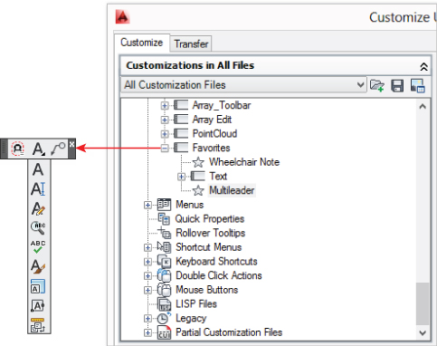
The following example explains how to create a new toolbar and add an existing toolbar as a flyout:
Figure 5.27 Structure of the Favorites toolbar in the CUI Editor and how it appears in the user interface
When a toolbar is created, it is added to all the workspaces currently defined in the customization (CUIx) file. Use the following steps to add the Favorites and Layers toolbars to the current workspace:
Shortcut and Temporary Override Keys
Shortcut and temporary override key combinations are used to execute a command macro. A temporary override key combination can also execute a second macro when the key combination is released. Both key types require you to define a key combination that includes at least the Shift, Ctrl, or Alt key and, in almost all combinations, one or more of the standard and virtual keys on the keyboard.
- All keys
- Accelerator (shortcut) keys
- Temporary Override Keys
- All
- Active
- Inactive
- Unassigned
- Click Copy To Clipboard to copy a tab-delimited list of all the keys currently displayed in the list.
- Click Print to output a list of all the keys currently displayed in the list.
The following example explains how to create a shortcut key that starts the Wheelchair Note command created earlier in this chapter:
You can use these steps to create a new temporary override key that toggles the current setting of the osnapz system variable:
Double-Click Actions
Double-click actions, as the name implies, are actions performed when you double-click something; in this case, that something happens to be a drawing object in the drawing window. While a double-click action starts a command macro that is defined in the Command List pane, all of the commands assigned to the default double-click actions edit the drawing object that was double-clicked.
When possible, a specific object-related editing command is started. For example, mtedit is started when you double-click a multiline text object, or pedit is started for a polyline object. If an object does not have a double-click action defined in the main customization (CUIx) file, the Properties palette is displayed. As a double-click action is defined, you must specify the type of object that the double-click action should be performed on using the object's DXF Code 0 value. You can figure out the DXF 0 Code value for an object by using the information I mentioned earlier, in the “Object Mode Shortcut Menus” section.
The following explains how to create a double-click action for an RTEXT object that is created with the rtext command that is part of Express Tools:
Other Elements
The AutoCAD user experience has changed and evolved over the years, and so have the elements of the user interface. The ribbon and Quick Access toolbar (QAT) for the most part have replaced the use of pull-down menus and toolbars that were the primary ways of accessing commands for over a decade. The user-interface elements that I have covered in this chapter are the main user-interface elements that are most frequently used and customized. There are a few others that are not as frequently customized or are basically retired from the product. These other user-interface elements include the following:
Mouse Buttons
You can specify the actions assigned to each button on your pointing device, with the exception of the left or primary mouse button, which is always the pick button. In addition to customizing the basic click event performed by a mouse button, you can customize the click action taken when the Shift and Ctrl keys are held while pressing a mouse button.
Tablet Buttons and Menus
You can specify the actions assigned to each button on your tablet's pointer device, with the exception of the primary mouse button, which is always the pick. Some tablet pointer devices support up to 16 buttons. In addition to customizing the basic click event performed by a mouse button, you can customize the click action taken when the Shift and Ctrl keys are held while pressing a mouse button.
Tablet menus allow you to map which area of the tablet represents the digitizing and drawing areas, in addition to where you can click to start a command. To help users identify each of the areas and commands, you create an overlay that sits on top of the tablet.
Image Tile Menus
Image tile menus (also known as icon tile menus) allow you to associate a slide image with a command macro. The image tile menu was one of the first user interfaces that allowed you to associate an image with a command macro. The images used for the menus were created with the mslide command. Multiple slide images can be combined into a slide library and used with the image tile menu. It is common to see image tile menus used to insert blocks, but they can be used to pass values to an AutoLISP or other custom program.
Screen Menus
The screen menu is a user interface that is kind of like a stack of papers. Clicking an item on the screen menu can execute a command macro or jump to a different page in the screen menu. Until recently, the screen menu was one of the oldest active user-interface elements that you could use and customize, but it has recently been retired. The screen menu can be displayed and customized after the screenmenu system variable has been redefined using the redefine command in AutoCAD 2014. Earlier releases do not require you to redefine the screenmenu system variable.
Dashboard Panels
The Dashboard palette was removed from the product in AutoCAD 2009. If you are migrating from an earlier release, you can convert a dashboard panel to a ribbon panel. Dashboard panels, if they exist in a customization file, can be converted on the Transfer tab of the CUI Editor.
Refer to the product Help system for additional information on how to customize these user-interface elements or migrate them from a previous release so they can be used in the latest release.
Setting Up Rollover Tooltips and the Quick Properties Palette
Rollover tooltips and the Quick Properties palette, shown in Figure 5.28, allow you to quickly query and change the property values of an object. Instead of having to select an object to view its properties, you can position the cursor over an object to see the current value of several properties for an object in a tooltip. Which properties are displayed for the rollover tooltip can be customized using the CUI Editor.
Figure 5.28 Rollover tooltip and Quick Properties panel displaying the properties for an arc
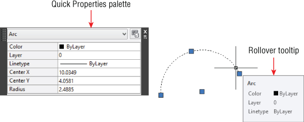
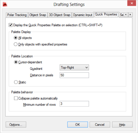
The Quick Properties palette (quickproperties command) is also a convenient way to query the property values of an object, but also to be able to edit values. You can specify which properties are displayed on the Quick Properties palette by using the CUI Editor, and you can control the appearance and behavior of the palette using the Quick Properties tab (see Figure 5.29) of the Drafting Settings dialog box (dsettings command).
Figure 5.29 Controlling the appearance and behavior of the Quick Properties palette
Use the following steps to customize the properties displayed on the rollover tooltip (or Quick Properties palette) for a Hatch object:
Figure 5.30 Modifying the properties displayed on the rollover tooltip for a Hatch object
Organizing the User Interface with Workspaces
Workspaces are used to control which user-interface elements are displayed and where they are positioned in the AutoCAD user interface. You can create and modify a workspace using the CUI Editor or directly manipulate elements in the user interface. If you show/hide user-interface elements or change their position from the AutoCAD user interface, you can save the changes to the current workspace or a new workspace with the wssave command. Directly manipulating user-interface elements is often easier than using the CUI Editor, but not all elements can be directly manipulated.
After you create a new element in the CUI Editor, you can control how and where that element is displayed with the Workspace Contents pane. Earlier in this chapter, I explained how to add a ribbon tab, pull-down menu, and toolbar to the current workspace. In earlier sections, I had you working with the current workspace only, but you can modify any workspace in the main customization (CUIx) file, create a new workspace, or even duplicate a workspace.
It is not uncommon to create multiple workspaces. For example, AutoCAD comes with several workspaces that are designed for people who are doing 2D drafting or 3D modeling. You could create separate workspaces for those who work on mechanical, architectural, or civil drawings within your company. You might also encourage users to create their own workspaces with their favorite tools, following your company standards.
These steps explain how to create a new workspace based on the Drafting & Annotation workspace that is defined in the acad.cuix file:
- Select the Quick Access Toolbar node and specify if you want to display the QAT above or below the ribbon.
- Expand the Toolbars node and select the first toolbar. Change the settings in the Properties pane as needed. Do this for each toolbar that is under the Toolbars node.
- Expand the Menus node and drag to reorder the pull-down menus for the menu bar.
- Expand the Palettes node and select the first palette. Change the settings in the Properties pane as needed. Do this for each palette that is under the Palettes node.
- Expand the Ribbon Tabs node and select the first tab. Change the settings in the Properties pane as needed. Do this for each tab that is under the Ribbon Tabs node.
- Expand the first ribbon tab node under Ribbon Tabs, and select the first panel. Change the settings in the Properties pane as needed. Do this for each panel that is on the selected ribbon tab, and then do this for each tab that is under the Ribbon Tabs node.
You can also change the display state and position of user-interface elements from the AutoCAD user interface and update a workspace by doing the following:
- Quick Access toolbar: Right-click over a command or control, and then click Show Quick Access Toolbar Below/Above The Ribbon to move the QAT above or below the ribbon.
- Ribbon tabs: Right-click over a tab and click Show Tabs, and then click the tab you want to show/hide that is associated with the current workspace. You can also click and drag a tab on the ribbon to change its display order.
- Ribbon panels: Click a tab to set it as current and then right-click over the tab. Click Show Panel and then click the panel you want to show/hide that is associated with the tab. You can also click and drag a panel on the ribbon to change its display order, or even drag the panel outside of the ribbon to float the panel. When floating, the panel remains displayed even upon switching tabs.
- Toolbars: On the ribbon, click View tab → User Interface panel → Toolbars drop-down menu → <Customization Group Name> and then the name of the toolbar you want to show or hide. After a toolbar is displayed, drag it on the screen and along the inner edges of the application window to dock it.
- Pull-down menus: On the Quick Access toolbar, click the Customization menu button located on the right side. Click Show/Hide Menu Bar to control the display of the menu bar and pull-down menus. The menubar system variable can also be used to display or hide the menu bar. You can't add or remove pull-down menus from the user interface unless you load a partial menu or use AutoLISP or a custom program.
- Palettes: On the ribbon, click View tab → Palettes and click the palettes you want to display as part of the workspace. After a palette is displayed, drag it on screen and along the edges of the application window to dock it.
- Status bar: On the status bar, click the Application Status Bar Menu button and click Drawing Status Bar to control the state of the application and drawing-window status bars. You can also control the state of the status bar with the statusbar system variable.
After you have created a workspace, you must set it as current before the changes to the user interface will take place. Use any of the following methods to set a workspace as current:
- Select a workspace from the Workspace drop-down list on the QAT, or choose one from the Workspace Switching icon on the status bar.
- In the Customizations In pane of the CUI Editor, expand the Workspaces node and select the workspace you want to set as current. Right-click the workspace and select Set Current.
- On the Workspace toolbar, select a workspace from the Workspace drop-down list.
- Prior to launching AutoCAD, you can use the /w command-line switch with a Desktop shortcut to set a specific workspace as current. For more information on command-line switches, see Chapter 4, “Manipulating the Drawing Environment.”
- While AutoCAD is running, you can use the wscurrent system variable to see which workspace is current and even switch workspaces.
Working with Customization Files
Customization (CUIx) files are used to store the definitions of the elements that make up most of the AutoCAD user interface. acad.cuix is the default customization file that ships with AutoCAD, and it's the file that you have been customizing throughout this chapter if you're using the default AutoCAD installation. You can create and load additional customization (CUIx) files that contain just your customization with the CUI Editor. I explain how to create and load CUIx files later in the “Creating CUIx Files” and “Loading CUIx Files” sections. When a CUIx file is loaded, you can also load any AutoLISP files that might be required for the command macros defined in the file. I discuss loading AutoLISP files that are related to a CUIx file later in this chapter in the “Loading AutoLISP Files” section.
Earlier AutoCAD releases shipped with files named acad.mnu and acad.cui, which were used to store the element definitions of the user interface. You can migrate user-interface elements from earlier releases using the Transfer tab of the CUI Editor. I explain how to transfer elements between two customization files in the “Transferring User-Interface Elements between CUIx Files” section.
The AutoCAD user interface supports three types of customization files:
Main
The main CUIx file should be writeable and typically contains most of, if not all, of the default AutoCAD user-interface elements. In most configurations, this is the acad.cuix file that ships with AutoCAD.
Enterprise
The enterprise CUIx file is read-only by design and typically contains your corporate customization, but it could also be the acad.cuix file that ships with AutoCAD. When the acad.cuix file is designated as the enterprise CUIx file, then your corporate customization is often designated as your main CUIx file. The enterprise CUIx file itself might not be marked as read-only, but the CUI Editor does not allow you to make changes to it.
Partial
Partial customization files, as the name implies, do not contain all of the elements that you might find in the standard AutoCAD user interface. The user-interface elements used by third-party utilities and plug-ins, and even the Express Tools user-interface elements, are often implemented with partial CUIx files. These typically contain a few toolbars, ribbon tabs and panels, and pull-down menus, but they can also contain dozens of additional user-interface elements.
No matter whether you use all three types of customization files or just a main CUIx file, consider storing your CUIx file in a centralized location so it can be shared with others. I recommend that you use a partial CUIx file at least for your personal and corporate customization so that you can share it with others in your company, and to make it easier to back up and transition to the latest release.
Creating CUIx Files
No matter whether you are creating a main, enterprise, or partial CUIx file, the process is exactly the same. The contents and how the file is being loaded are what differentiate one from another. While you can copy and rename a CUIx file through Windows Explorer or File Explorer, you should avoid doing so because it does not change the customization group name inside the file.
The following steps show how to create a new CUIx file named myui.cuix:
If you want to create a new CUIx file from an existing CUIx file, you will want to open the file and then save it with a new name. Use these steps to open and save a CUIx file with a different name:
Loading CUIx Files
After you create a CUIx file or obtain a CUIx file from a third-party developer or consultant, you must load it so the elements defined in the file can be accessed from the AutoCAD user interface. How you plan to use a CUIx file determines how the file needs to be loaded. You can load a CUIx file using one of the following options:
Main Customization File
Click the Application Menu button and then click Options. In the Options dialog box, select the Files tab and expand the Customization Files node. Expand the Main Customization File node and select the path to the CUIx file. Click Browse. In the Select A File dialog box, browse to and select the CUIx file you want to load as the main customization file. Click Open, and then click OK to close the Options dialog box.
Enterprise Customization File
Click the Application Menu button and then click Options. In the Options dialog box, select the Files tab and expand the Customization Files node. Expand the Enterprise Customization File node and select the path to the CUIx file. Click Browse. In the Select A File dialog box, browse to and select the CUIx file you want to load as the enterprise customization file. Click Open, and then click OK to close the Options dialog box.
![]()
Partial Customization File
On the ribbon, click Manage tab → Customization panel → User Interface. In the CUI Editor, select the Customize tab, and in the Customizations In pane, click Load Partial Customization File. In the Open dialog box, browse to and select the CUIx file that you want to load. Click Open. The CUIx file is added to the Partial Customization Files node of the main customization file.
Transferring User-Interface Elements between CUIx Files
The CUI Editor not only allows you to create and modify elements for the user interface and manage CUIx files, but also lets you copy or migrate elements between two CUIx files or an earlier menu source (MNS) or customization (CUI) file. You transfer elements between files using the Transfer tab. Load the files that you want to work with, and then drag elements between the available nodes in the Customization In panes. Transferring an element also transfers any associated commands, ribbon panels, and toolbars. When transferring elements, you can only drag and drop elements of the same type. So, there's no dragging ribbon tabs to a Quick Access toolbar (QAT).
Loading AutoLISP Files
It is not uncommon that the commands in your CUIx files might use functions or commands defined in an AutoLISP file. There are a few different methods that you can use to make sure that the AutoLISP programs your user-interface elements rely on are loaded for use by your CUIx file. The following outlines the methods you can use to load an AutoLISP file for use with a CUIx file:
- AutoCAD searches for an AutoLISP Menu (MNL) file that has the same name as a CUIx file that is being loaded. If the MNL file is located, AutoCAD loads it along with the CUIx file into each drawing that is created or opened while the CUIx file is loaded.
- Using the CUI Editor, you can add AutoLISP (LSP) files to the LISP Files node. These files are loaded when the CUIx file is loaded and a new drawing is created or opened.
- Using the Load/Unload Applications dialog box (appload command), you can manually load an AutoLISP (LSP) file or add it to the Startup Suite. The Startup Suite loads the files that are listed when a new drawing is created or an existing drawing file is opened.
Controlling the Tools on the Status Bars
AutoCAD supports two status bars: drawing and application window. By default, both are combined into a single bar and displayed along the bottom of the application window. While you can control which tools are displayed, you can't create and place new tools on the status bar. Even though you can't add new tools, it can be helpful to hide those that you do not use, such as 3D Object Snap and Allow/Disallow Dynamic UCS if you do not work on 3D models.
Unlike other user-interface elements, the settings that control the display of the tools on the toolbar are not stored in the CUIx file or controlled by the current workspace, with the exception of the current status-bar state (statusbar system variable). To control which tools are displayed on the status bar, do one of the following:
Application Status Bar Menu
Click the Application Status Bar Menu button (see Figure 5.31) to control the display of the coordinates area and drafting aids on the status bar. You can also access controls related to layers, drawing views, workspaces, and display locking, among others. This menu allows you to display the Tray Settings dialog box and toggle the display of the drawing status bar.
Figure 5.31 Controlling the display of tools on the status bar
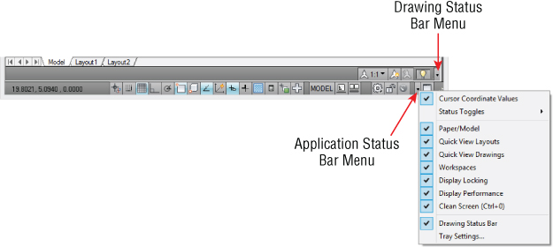
Drawing Status Bar Menu
When the drawing status bar is displayed, it contains the controls related to annotation scaling and the system tray. Click the drawing status-bar menu to toggle which annotation scaling tools you want to display.
Tray Settings Dialog Box
Controls the display of icons and notifications for services that are running in the application or current drawing. You can also specify the duration that a notification is displayed for, or whether it is displayed until you close it. The actual enabling or disabling of a service is not handled in this dialog box; you must do that on a feature-by-feature basis. For example, you can use the xrefnotify system variable to control the display of xref notifications or the layernotify system variable to display alerts for unreconciled new layers.