Chapter 8
Automating Repetitive Tasks
In Chapters 5 through 7, I discussed how to create custom elements and tools that could be accessed from the user interface. These elements and tools make it easy to execute command macros, which are often designed to start and pass values to the current command.
While a command macro can help you combine multiple commands into a single action, two features of the Autodesk® AutoCAD® program are specifically designed to help reduce and automate repetitive tasks: scripts and action macros. You'll learn how to work with both scripts and action macros in this chapter.
Creating and Running Scripts
Scripts are one of the oldest methods that you can use to automate repetitive tasks in AutoCAD. For example, scripts can open, save, and close a drawing file—an AutoLISP® program can't. You can use scripts for a number of different purposes; here are a few of the most common uses for script files:
- Update the CAD standards in one or more drawings
- Change the settings and nongraphical objects in the drawings that you receive from a client
- Execute a series of commands with specific values in a drawing
The following list outlines the known limitations of scripts:
- Unlike command macros, scripts do not support a way to pause execution and prompt a user for input directly. You can use AutoLISP expressions to request input for a command.
- Dialog boxes should be avoided with scripts. Starting a command that displays a dialog box suspends the script that is executing when the dialog box opens and then resumes the script when the dialog box is dismissed. The problem with displaying a dialog box is that the responses a user provides might not produce the results that were originally intended when the script was written.
- AutoCAD can execute only a single script file at a time, so a script file can't start the script command to execute another script.
What Is a Script?
A script file is an ASCII text file that can contain AutoCAD commands, values, and AutoLISP expressions. You can create a script file using a text editor, such as Notepad on Windows or TextEdit on Mac OS. After you create a script file, you must save it with the ANSI encoding and the .scr file extension.
The content of a script file mimics the commands and values that you would enter at the AutoCAD command prompt. For example, the following command sequence controls some of the settings in model space, creates a new layer, and then adds a rectangle and a single-line text object:
Command: grid
Specify grid spacing(X) or [ON/OFF/Snap/Major/aDaptive/Limits/Follow/Aspect]
   <0.5000>: off
Command: ltscale
Enter new linetype scale factor <1.0000>: 48
Regenerating model.
Command: -layer
Current layer: "0"
Enter an option [?/Make/Set/New/Rename/ON/OFF/Color/Ltype/LWeight/TRansparency/
   MATerial/Plot/Freeze/Thaw/LOck/Unlock/stAte/Description/rEconcile]: new
Enter name list for new layer(s): border
Enter an option [?/Make/Set/New/Rename/ON/OFF/Color/Ltype/LWeight/TRansparency/
   MATerial/Plot/Freeze/Thaw/LOck/Unlock/stAte/Description/rEconcile]: color
New color [Truecolor/COlorbook] : 9
Enter name list of layer(s) for color 9 <0>: border
Enter an option [?/Make/Set/New/Rename/ON/OFF/Color/Ltype/LWeight/TRansparency/
   MATerial/Plot/Freeze/Thaw/LOck/Unlock/stAte/Description/rEconcile]:
Command: rectang
Specify first corner point or [Chamfer/Elevation/Fillet/Thickness/Width]: 0,0
Specify other corner point or [Area/Dimensions/Rotation]: 1056,816
Command: -text
Current text style: "Standard" Text height: 0.2000 Annotative: No
   Justify: Left
Specify start point of text or [Justify/Style]: 20,20
Specify height <0.2000>: 12
Specify rotation angle of text <0>: 0
Enter text: This is a sample startup script.
Command: zoom
Specify corner of window, enter a scale factor (nX or nXP), or
[All/Center/Dynamic/Extents/Previous/Scale/Window/Object] <real time>: extents
Regenerating model.
An example script containing the same commands and values as those entered at the command prompt might look something like Listing 8.1.
Listing 8.1: Startup Script example
; Created 10/1/2013 by Lee Ambrosius - Startup Script
grid off
ltscale 48
-layer new border color 9 border set border
rectang 0,0 1056,816
-text 20,20 12 0 This is a sample startup script.
zoom extents
Special Characters in a Script
You should be aware of a few special characters when it comes to writing scripts. These characters include the following:
Semicolon (;)
A semicolon denotes a comment; everything to the right of the semicolon is ignored. The first line of the Startup Script example shows what a comment looks like in a script. You can use comments to identify who created a script or when a script was created, as well as the purpose of the script.
Space
A space in a script has two different meanings; it can represent either the press of the Enter or Return key or an actual space in a text string. The action a space represents is the same as it would be if you pressed the spacebar at the AutoCAD command prompt.
Carriage Return/Hard Return
A carriage return is added when the Enter or Return key is pressed. It is just like pressing Enter or Return when typing commands and values at the AutoCAD command prompt.
As an alternative, the commands and values in a script can be placed on separate lines. Listing 8.2 shows what the Alternative Startup Script example might look like if each command and value were placed on separate lines.
Listing 8.2: Alternative Startup Script example
; Created 10/1/2013 by Lee Ambrosius - Alternative Startup Script
grid
off
ltscale
48
-layer
new
border
color
9
border
set
border
rectang
0,0
1056,816
-text
20,20
12
0
This is a sample startup script.
zoom
extents
Alternatives to Dialog Boxes
As I mentioned earlier, you should avoid the use of commands that display dialog boxes with scripts. Table 8.1 and Table 8.2 show many of the commands that start dialog boxes, as well as the commands or system variables that you should use instead when writing scripts.
Table 8.1 Command-line equivalent commands (Windows and Mac OS)
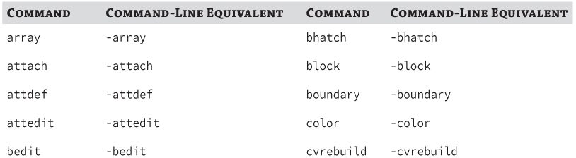
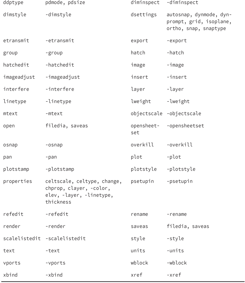
Table 8.2 Command-line equivalent commands (Windows only)
Creating a Script
Since a script file is a plain ASCII text file, you can create and edit it with Notepad on Windows or TextEdit on Mac OS.
The following explains how to create a script file named startup.scr on Windows:
- On Windows XP or Windows 7, click the Start button → [All] Programs → Accessories → Notepad.
- On Windows 8, on the Start Screen, type note and then click Notepad.
; Created 10/1/2013 by Lee Ambrosius - Startup Script
grid off
ltscale 48
-layer new border color 9 border set border{SPACE}
rectang 0,0 1056,816
-text 20,20 12 0 This is a sample startup script.
zoom extents
If you are running AutoCAD on Mac OS, use the following steps to create a script file named startup.scr:
; Created 10/1/2013 by Lee Ambrosius - Startup Script
grid off
ltscale 48
-layer new border color 9 border set border{SPACE}
rectang 0,0 1056,816
-text 20,20 12 0 This is a sample startup script.
zoom extents
Running a Script
After you create a script file, you can run it using the script command. You can also run a script when AutoCAD first starts up using the /b and -b command-line switches. I covered command-line switches in Chapter 4, “Manipulating the Drawing Environment.”
The following explains how to run a script file named startup.scr at the AutoCAD command prompt. You can create the script file by completing the example under the “Creating a Script” section earlier in this chapter, or you can obtain the file by downloading the book's sample files from www.sybex.com/go/autocadcustomization. Once downloaded, extract the files to a folder named MyCustomFiles under the Documents (or My Documents) folder of your user profile, or a folder of your choice.
- On the ribbon, click Manage tab → Applications panel → Run Script (Windows).
- At the command prompt, type script and press Enter. (You could also use the -script command to enter the location and name of the script you want to run at the command prompt instead of using the Select Script File dialog box—on Windows and Mac OS.)
While a script is executing, you can press the Esc or Backspace key to pause it. After a script is paused, you can start running the script where it left off by issuing the resume command. Once a script is finished, you can run the script again using the rscript command. An additional command that is related to working with scripts is the delay command, which is used to pause a script for a specified duration of time that is expressed in milliseconds.
Recording Action Macros (Windows Only)
Action macros were first introduced with AutoCAD 2009 and are the next evolution of script files. Scripts and action macros share some similarities, but as I demonstrate in this section, action macros are easier to create because you create them interactively from the AutoCAD user interface instead of using Notepad.
An action macro is created using the Action Recorder on the ribbon, and then saved to a file with the .actm extension. Once an action macro is saved, you can edit the values in the recorded actions and the behavior of the action macro using the Action tree of the Action Recorder. Playing back an action macro is as simple as starting a standard AutoCAD command.
What Is an Action?
An action is the smallest user interaction or task that can be recorded from the AutoCAD user interface with the Action Recorder. An action might be the result of starting a command, entering a value at the command prompt, specifying a point in the drawing area, or even changing an object's property value with the Properties palette.
While the command prompt will serve as your main method for starting commands and specifying command options and values, you can also use a variety of other methods for starting commands and providing input. The following lists most of the other ways that you can start a command or change a value using the user interface when recording an action macro:
- Application menu and Quick Access toolbar
- Ribbon panels, toolbars, and pull-down and shortcut menus
- Application and drawing-window status bars
- Properties and Quick Properties palettes
- Tool Palettes window
- Input provided with the input device (coordinate values and selection sets)
There are some other types of commands that you should avoid in addition to ones that display dialog boxes. These commands are related to opening, creating, and closing drawings, as they (along with a few other commands) can't be recorded with the Action Recorder. If you attempt to enter a command that can't be used while the Action Recorder is in recording mode, the following message will be displayed in the Command Line History window:
** ACTRECORD command not allowed during recording an action macro **
Using the Action Recorder
The Action Recorder is a panel on the ribbon, as shown in Figure 8.1, which you use to record actions so they can be played back later to automate a repetitive task. You also use the Action Recorder panel to modify and manage previously recorded action macros. You can display the Action Recorder by clicking the Manage tab on the ribbon.
Figure 8.1 Action Recorder panel on the ribbon
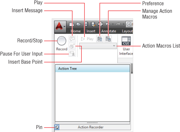
The following explains the various components of the Action Recorder panel:
Record/Stop
The Record button starts the recording of actions (actrecord command). After you are done recording actions, clicking the Stop button displays the Action Macros dialog box (actstop command). From the Action Macros dialog box, you can choose to save or discard the recorded actions. Saving the recorded actions results in the creation of an ACTM file.
Insert Message
The Insert Message button allows you to add to the current action macro in the Action Tree an action that displays a message box with a custom message during playback. When clicked, the Insert User Message dialog box is displayed. You can also use the actmessage command when you are recording an action macro.
Play
The Play button starts the playback of the action macro shown in the Action Macros drop-down list. An action macro can also be played back by entering its name (without the file extension) at the command prompt.
Preference
The Preference button displays the Action Recorder Preferences dialog box, which allows you to control the settings that affect the Action Recorder panel when creating or playing back an action macro.
Manage Action Macros
The Manage Action Macros button displays the Action Macro Manager, which allows you to copy, rename, modify, and delete the action macro files found in the locations specified on the Files tab of the Options dialog box. You can also use the actmanager command to display the Action Macro Manager.
Action Macros List
The Action Macros drop-down list displays all of the action macros that are available for playback, beginning with the ones you have most recently played back. Recently played action macros are located at the top of the list. Below the separator bar, all available action macros are listed. Clicking the Manage Action Macros item at the bottom of the drop-down list displays the Action Macro Manager.
Action Tree
The Action Tree displays all of the actions and values that make up a currently selected action macro or the action macro that is currently being recorded.
Insert Base Point
The Insert Base Point button adds a base point-action to the current action macro in the Action Tree. A base point action establishes a new absolute coordinate point that the next relative point uses as its reference point. You can also use the actbasepoint command when you are recording an action macro.
Pause For User Input
The Pause For User Input button allows you to prompt the user to specify a new value for an action during playback. This button acts like a toggle for the selected action value in the Action Tree; it switches a value from static to interactive or an interactive value back to a static value. You can also use the actuserinput command when you are recording an action macro.
Recording Actions for Playback
Recording actions in AutoCAD to create an action macro is similar to recording your favorite movie or TV show using a digital video recorder. You click the Record button (actrecord command) to start recording actions that are performed in the AutoCAD user interface. Once recording has started, the button changes from Record to Stop. After you are done recording actions, click the Stop button (actstop command) and then save or discard the recorded actions.
The following example explains how to record an action macro that creates a layer named Hardware and inserts a block from the Tool Palettes window.

Figure 8.2 The Action Tree shows recently recorded actions.
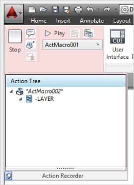
Figure 8.3 Recorded actions and values used to create a new layer named Hardware with the color blue
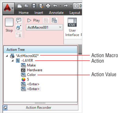

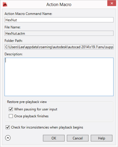
Figure 8.4 Saving recorded actions to an action macro
Now that you have created an action macro file, you can play it back by doing one of the following:
- At the command prompt, enter the name of the action macro you want to execute. (The name of the action macro is the same as the action macro's file, but without its file extension.)
- On the Action Recorder panel, select from the Action Macros list the action macro you want to play back, and click Play.
- Right-click in the drawing area, and then click Action Recorder → Play and the action macro you want to execute from the submenu.
The following example explains how to execute the HexNut action macro you just created:
The following explains how to change the action macro to prompt for an insertion point when the block is being inserted:
I will discuss other ways that you can modify an action macro in the next section.
Modifying Action Macros
After an action macro has been created and saved, you can modify its properties or the actions that make it up. You can perform the following tasks to modify an action macro:
- Pause an action macro for input
- Edit the value of an action
- Toggle a coordinate or all coordinates between relative and absolute
- Insert a user message into an action macro
- Insert a base point
- Remove an action from an action macro
Pausing for Input
You can have an action macro request a new value for a previously recorded value by doing the following:
- In the main area of the Action Recorder panel, click Pause For User Input.
- In the Action Tree, right-click a node and click Pause For User Input.
Editing a Recorded Value
A recoded value can be changed by following these steps:
Toggling between Absolute and Relative Coordinate Values
Recorded coordinate values are all relative to the first coordinate point that is specified when recording actions. You can toggle a relative coordinate value to an absolute coordinate that you specified in the drawing window while the value was being recorded. Use the following example to toggle a coordinate value from relative to absolute or absolute to relative:
If you want to make all coordinates absolute or relative with the exception of the first coordinate value, do the following:
Inserting a User Message
You can display a message box during the playback of an action macro by doing the following:
- In the main area of the Action Recorder panel, click Insert Message.
- In the Action Tree, right-click a node and click Insert User Message.
Inserting a Base Point
A base point in an action macro allows you to establish an absolute coordinate point that the next relative coordinate point references. The following steps explain how to insert a base point into an action macro:
- In the main area of the Action Recorder panel, click Insert Base Point.
- In the Action Tree, right-click a node and click Insert Base Point.
Removing an Action
Actions, base points, and user messages can be removed from an action macro, but an individual recorded value can't be removed. For example, if you recorded the Color option of the layer command, you can't remove the Color value that was entered. However, you can remove the action that contains the recording of the layer command and any responses to the layer command. You can remove an action, base point, or user message by doing the following:
Managing Action Macros
After action macros have been saved to ACTM files, you can manage the files with the Action Macro Manager (actmanager command). The following tasks can be performed from the Action Macro Manager:
- Copy an action macro
- Rename an action macro
- Delete an action macro
- Edit the properties of an action macro
Creating a Copy of an Action Macro
You can create a copy of an existing action macro by doing the following:
Renaming an Action Macro
You can rename an existing action macro by doing the following:
Deleting an Action Macro
You can delete an existing action macro by doing the following:
Changing the Properties of an Action Macro
After an action macro has been saved, you can change its properties by doing the following:
Sharing and Specifying Paths for Action Macros
Action macro files can be shared with others by simply copying ACTM files from one workstation to another, or posting them to a shared location. While copying an ACTM file is straightforward, all workstations that the action macro will be played back on must have access to the following:
- Commands that were used during the recording of the action macro
- Files that were used by the commands in the action macro
AutoCAD loads any ACTM files it finds in the folders listed under the Action Recorder Settings node on the Files tab of the Options dialog box (options command). The Action Recorder Settings node contains two child nodes:
Actions Recording File Location
The folder listed under this node is used to store newly recorded ACTM files. Files located in the folder can also be edited and played back. You can also use the actrecpath system variable to query and set the folder used by the Action Recorder.
Additional Actions Reading File Location
The folders listed under this node are searched for additional ACTM files that can be played back only. This node is where you might specify a network location that contains all of the ACTM files that are shared with everyone in your company or department. You can also use the actpath system variable to query and set the folders used by the Action Recorder.