
Autodesk first added limited 3D capabilities to Release 2.1 back in the technological olden days of 1985 and then periodically introduced new 3D functions in subsequent releases. But it wasn't until AutoCAD 2007 that 3D came into its own. That release shipped with a huge number of features dedicated to creating and presenting models. AutoCAD was already a very good modeler even before AutoCAD 2007, though, so why haven't more AutoCAD users taken advantage? Three reasons:
An inaccurate sense that 3D is too hard
A false perception that AutoCAD is a lousy 3D modeler
A mistaken belief that 3D modeling isn't worth the time
Let's knock down these reasons one at a time. Is it too hard to learn 3D modeling? No. Even if you've never created a single 3D model in AutoCAD, you know 80 percent of what you need to know: that is, how to create accurate 2D geometry.
Is AutoCAD a lousy modeler? Of course not. It's not as good as some other modelers in certain respects—hence the bad rap. It may not be the gold standard, but so what if Inventor, Architectural Desktop, Mechanical Desktop, VIZ, Revit, and a bunch of other applications have 3D modeling strengths that AutoCAD doesn't have? You paid several thousand dollars for AutoCAD, so why not use everything you paid for? And for you, AutoCAD 3D has one advantage that none of the other software has: familiarity.
Is 3D modeling worth the time? Absolutely. You can produce useful 3D models fairly quickly, as long as you understand some easily mastered basics. Once you've created those models, you can use them for all kinds of things: solving design problems, showing off to customers, laying out views for plotting, exporting for use in other programs, controlling CNC manufacturing processes, and so on.
A Brief Overview
Managing Coordinate Systems
Managing Views and Viewports
Creating a Model
Using Existing 2D Geometry
Final Suggestions
The purpose of this chapter is to introduce you to AutoCAD 3D by helping you understand how to get around in space, how to manage views of your model, and how to use a handful of 3D commands. You'll make a simple model, step by step; you'll look at a strategy for creating a quick perspective line drawing using existing 2D architectural elevations; and you'll see a neat trick for creating a mechanical part with the INTERSECT command.
You may be surprised, even stunned, by the wide array of individuals and companies that produce useful, professional work with AutoCAD 3D. Let's begin by looking at some projects that were modeled entirely in AutoCAD.
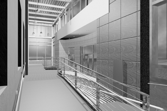
The interior view in Figure 10.1 is an image of the Maine state office building. Meridith Comeau produced this model several years ago for the architectural firm SMRT in Portland, Maine. She imported the AutoCAD model into Autodesk VIZ, added materials, and created a rendered animation to show at a public hearing prior to construction. The firm made several design changes as a result of the feedback from the public and state employees who would be using the building.
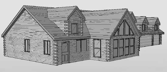
The log-home image in Figure 10.2 was created by Paul Richardson for Katahdin Cedar Log Homes in Oakfield, Maine. He didn't model it himself: He wrote the automation program that takes advantage of AutoCAD's modeling capabilities to generate a solid model of every component using input from a designer. The automation program then converts the DWG file into the CNC code required to select, cut, drill, machine, bar-code, and stack each piece. The entire set of logs is then shipped to a site where it's assembled into a home—the most notable version of which was used on the television show Extreme Makeover Home Edition for a family in Maine.
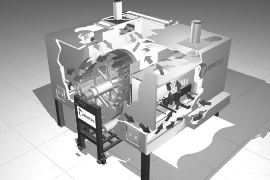
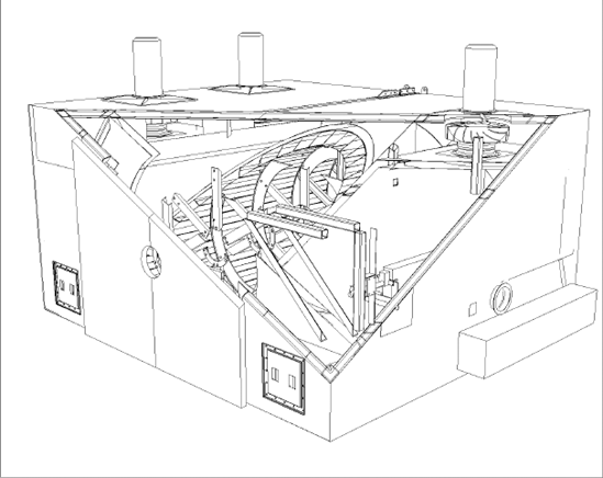
Meridith Comeau also produced the large dryer unit shown as a rendered image in Figure 10.3. Metso Paper USA designed this device for the tissue-paper industry. The company used the model to demonstrate the unique aspects of its dryer unit. Since then, Metso Paper has manufactured a number of these units for clients around the world. Figure 10.4 shows a hidden view of the AutoCAD model.
You can create and display models in several forms. We'll take a quick look at wireframe, flat surface, and swept-surface models, but the rest of this chapter will be devoted to getting you started with solid modeling.
Wireframe models AutoCAD began as a 2D drawing program in 1982. Its only 3D capabilities were the same as those in board drafting—isometric and oblique drawings that looked like 3D models. The earliest improvements in 3D allowed lines to be created using X, Y, and Z coordinates. The results generated a wireframe model—just the edges existed. It's like bending wire into various shapes: Your object appears in three dimensions, but all the edges are visible from any viewpoint. It's still possible to create wireframe models in AutoCAD, of course, by drawing the edges using lines, but such models don't have many uses. However, wireframe is still one of the most common display options for 3D models.
Flat-surface models A flat-surface model is the equivalent of stretching a sheet of rubber over a wireframe model. You can change an entity's thickness to turn it into a collection of flat surfaces. You can also use the 3DFACE command to cover a wireframe model with surfaces. Those block any lines behind them when VSCURRENT or SHADEMODE has a non-2D setting or the HIDE command is used. The result may look like a solid object, but it isn't. That doesn't mean it's not useful, because you can attach materials to it either in AutoCAD or another program like VIZ or 3ds Max. But it can't be edited like a solid.
Swept-surface models Curved and irregular surface modeling was added in R10 in the form of the RULESURF, TABSURF, REVSURF, and EDGESURF commands. They're still available and are sometimes used for creating quick shapes. The surfaces can be assigned materials that can be rendered—either in AutoCAD directly or by using a program like 3ds Max.
Solid models The most useful form for a 3D model is the solid model. Solid models are easy to make and can be combined with other solids to generate complex shapes. And you can take advantage of techniques that aren't possible with a real-world physical model. For example, you can use a Boolean intersection of two or more models that occupy the same space to make complex shapes. You'll see how to do that later in this chapter.
The most confusing aspect of 3D drawing for most 2D CAD operators is keeping track of their position when viewing or working on a 3D model. To avoid confusion when working in 3D, you must understand how to create, save, and use user coordinate systems. Let's define a few terms to demystify this process. Then, you'll make a simple model.
The world coordinate system (WCS) is the default coordinate system in a new drawing. Before AutoCAD 2007, when you started a new drawing, you always saw a plan view of the WCS—that is, looking straight down the Z axis at the ground or floor. In AutoCAD 2007, the plan view is what you see when you start a drawing with the AutoCAD Classic template. A drawing based on the 3D modeling template looks completely different, but the coordinate system is still the WCS. You just have a different view of it. Rather than looking straight down the Z axis, your view is from a point above the X-Y plane, south of the X axis and east of the Y axis.
In a plan view of the WCS, the origin point is always 0,0,0, with the X and Y axes forming a plane at a Z elevation of 0. Any positive value for Z appears above the plane; any negative value is below. You can't modify the WCS, nor would you want to, because it anchors you to one consistent origin point. However, you can and should create as many of your own coordinate systems as you need.
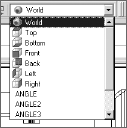
Unlike the WCS, a user coordinate system (UCS) can be placed at any origin and in any orientation. Its only restriction is that the three axes are always at 90° angles to each other. They're called user coordinate systems because the user can create them, but there's also a group of predefined user coordinate systems for standard orientations: Top, Bottom, Front, Back, Left, and Right. To use them, turn on the UCS II toolbar, and select them from the drop-down panel. You can add as many others as you want. To save them, use the Named UCS button on the same toolbar, or the DDUCS command (alias UC).
Note
AutoCAD 2007 has a dynamic UCS option that's controlled by moving the cursor over a face on a model. It's a wonderful tool, but we won't use it here. Instead, you'll create and use static UCSs. That way, this chapter will make sense to all AutoCAD users. But even AutoCAD 2007 users should know how to manage saved UCSs. Use the DUCS button on the status bar to toggle this feature on and off.
Note
All predefined UCSs have the same origin as the WCS. Don't make the mistake of thinking they'll be on a surface of your model, especially if you haven't placed a corner of your model at 0,0,0.
You have a number of options for creating a new UCS. The standard UCSs are rotated around the X and Y axes. Once you've created a model, the 3 Point option of the UCS command is quick and intuitive. You pick three points: the origin, a point on the positive X-axis, and a point on the positive Y-axis.
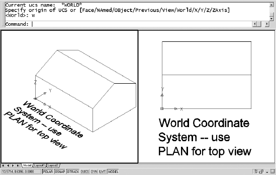
The view on the screen is independent of the coordinate system, unless you change the value of the system variable UCSFOLLOW from its default setting of 0 to a setting of 1. You can always match the view to your UCS, by using the PLAN command and selecting Current, which is the default option. To get an understanding of the relationship between coordinate systems and your view of them, look at the following figures.
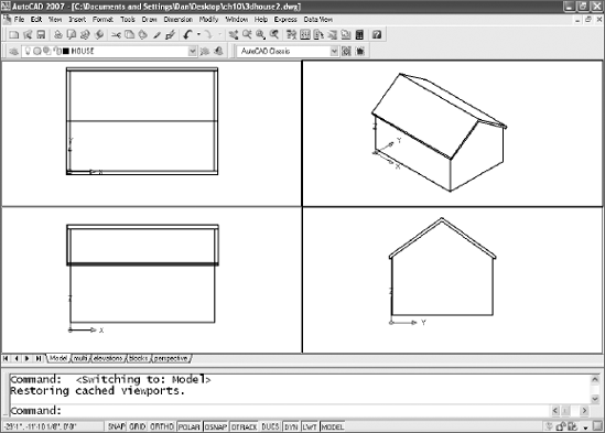
Figure 10.5 shows a simple house shape in both isometric and plan view with one corner at 0,0,0. WCS is the current coordinate system.
Note
If you always place one corner of your model at 0,0,0, you'll find it easier to locate points on the model.
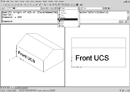
Figure 10.6 shows the same entity, after the Front UCS has been selected, and the PLAN command was used in the right viewport.
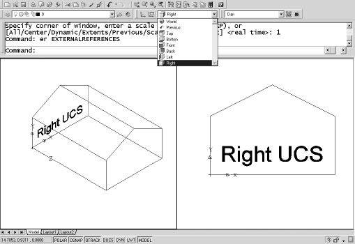
The Right UCS is current in Figure 10.7.
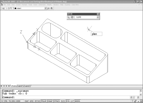
Finally, Figure 10.8 shows a UCS created with the 3-point option that sits on one sloped surface of the roof. Because this UCS isn't one that is listed in the toolbar, it was given the name Angle1 so it can be used again. Note that there are three viewports shown. The upper right viewport shows a plan view in the Angle1 UCS.
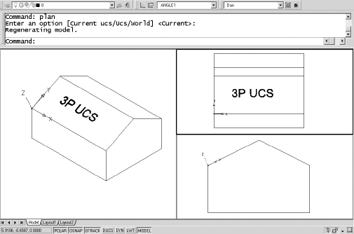
Note
The 3 Point option of the UCS command has been hidden in AutoCAD 2007. You can still use it by typing 3P or 3, but it isn't listed. Instead, the default option for UCS is Specify Origin Of UCS. After your first selection, you're given the option of selecting a point on the X-axis. That in turn gives you the option of selecting a point on the Y-axis. Use object snaps to locate each point. I normally use the NEA OSNAP override to select the X and Y locations so I can zoom in as close as possible to the origin.
Now that you've seen how UCSs are created, you've had enough preliminaries: Let's make a model. You'll start with a desk organizer. The text on the one you'll create will be recessed rather than raised, but otherwise, when you're done, it'll look like this.
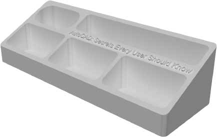
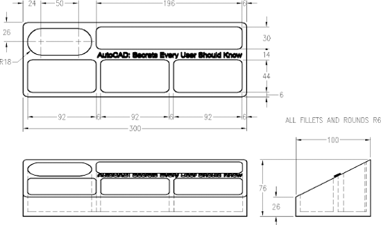
Just in case you want to use them, the dimensions of the desk organizer are shown in Figure 10.9. They're metric.
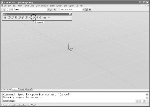
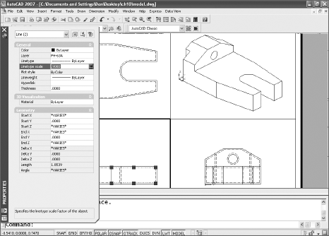
Before you get going, start a new metric drawing, and set the upper right corner of the limits to 320,120. If you're using AutoCAD 2007, switch to the AutoCAD Classic view in the Workspaces toolbar. If you started with a 3D template file, check the color assigned to the layer you're on. The default color may be hard to see, depending on the background color you use. For this tutorial, most toolbars and all tool palettes are turned off, but otherwise you'll have either the familiar plan view of the WCS or a screen that looks something like this:
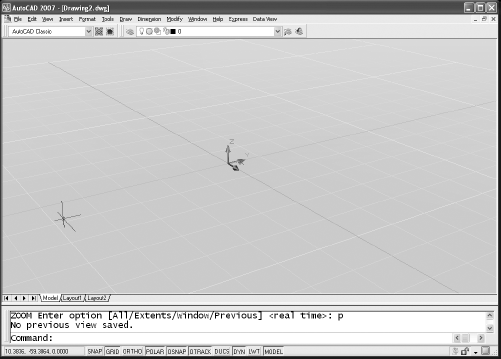
It will look a little different from the classic AutoCAD screen for only a few steps. Whatever view you're starting with, go through the following steps:
Display the View toolbar by right-clicking any tool button and selecting View from the pop-up menu. Set a southeast isometric view by selecting the button shown.
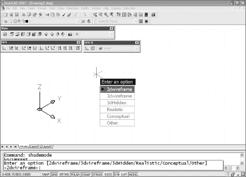
Display the two UCS toolbars (UCS and UCS II), and set SHADEMODE to 2D Wireframe. (In AutoCAD 2007, SHADEMODE is an alias for VSCURRENT—visual style current). From the menu, use View → Visual Styles → 2D Wireframe. Your screen will look more like those in the images that follow once you've made these changes.
Use the UCSICON command to set the properties to 3D with cones, as shown in the next figure. The small square at the intersection of all three axes is displayed only when the WCS is current. If you're in a UCS, the icon has no square. When the UCS icon is at 0,0,0, you see a crosshair at the intersection of the axes (it looks like the axes extend past each other). The crosshair disappears if 0,0,0 is off the screen, but the icon will still be displayed.
You can change the appearance of the icon by selecting the Properties option of the UCSICON command to get the dialog box shown.

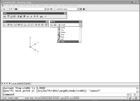
Use the UCS II toolbar to set a Right UCS by selecting it from the drop-down list. The UCSICON will change to represent the UCS you select.
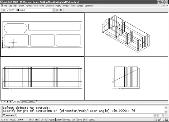
Use the PLINE command to draw the profile of the right-side view of the desk organizer, using the dimensions shown earlier in Figure 10.9. Start at 0,0,0, and make sure you close the polyline.
Note
I set DISPSILH to 1 before creating the images for this tutorial. That turns off tessellation lines used to represent curved surfaces on the screen. If DISPSILH is set to 0, you'll see a lot more lines on your model than appear in the images here
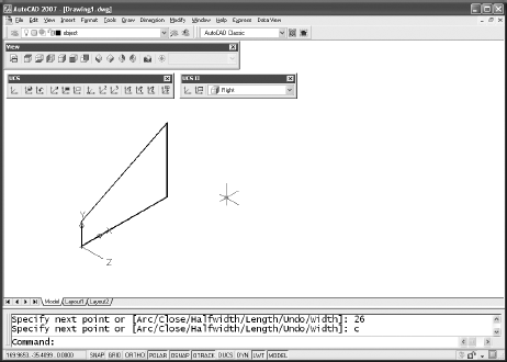
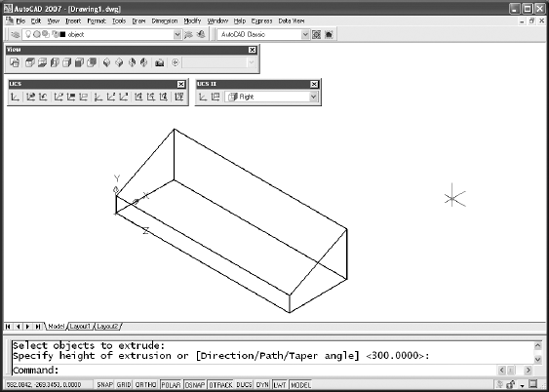
Use the EXTRUDE command to extrude the closed polyline 300 units in the positive Z direction by entering an extrusion height of 300. (If you're using a release prior to AutoCAD 2007, you're prompted for a taper angle. Use 0.) You've just created a solid that you'll use to make the desk organizer.
Note
When drawing shapes or creating solids, you can use the same drawing aids you've always used: osnaps, object tracking, polar tracking, temporary tracking, absolute coordinates, relative coordinates, polar coordinates, direct distance entry, and so on. But be careful—it's easy to snap to the wrong end of a line when working in a plan view. The isometric view is often your best bet when snapping to objects.
In step 4, when you made the Right UCS current, you probably noticed a number of other typical coordinate systems set up. You need only one additional UCS to complete this project, so let's make it now. Zoom in at the corner of the solid, and either type
UCS, then3, or select the 3 Point button on the UCS toolbar. This is one of the most useful ways to create a new UCS to work on a face of an existing solid.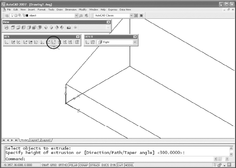
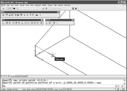
You're prompted to specify a new origin point. You can snap to it or type coordinates. After you select the corner of the sloped surface, you're prompted to specify a point on the positive portion of the X-axis. Resist the temptation to zoom out and select the endpoint of the front line. It'll work for this object, but when you're working on multiple solids, or when your objects are more complex, it's easy to snap to the wrong endpoint. Stay zoomed in, use the Nearest osnap, and select anywhere along the line.
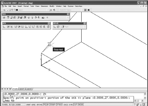
The next point is on the Y-axis, of course. Use Nearest again to snap to a location on the line. Now you have a new UCS that sits right on the sloped surface so you can place some text on it later.
Whenever you create a new UCS, save it. You can either type
UCS,Sand then type a name for the current UCS, or use the button shown on the UCS II toolbar, which will open the UCS dialog box. Unnamed is listed as the first UCS. Use a slow click, or double-click it, and give it a name that makes sense. Use the name "Slope" for this tutorial.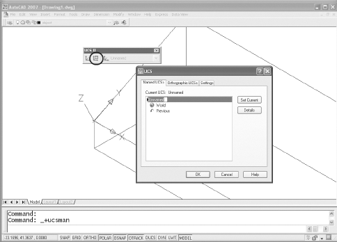
It's easy to lose your bearings when you're working on a 3D model, so you need to give yourself as much help as possible. Now that you have a basic shape and have saved a UCS, let's set up four views so it's easier to keep track of what's happening:
Restore the WCS by selecting World from the UCSII toolbar drop-down list.
Open the Viewports dialog box. Either type
VPORTSor use View → Viewports → New Viewports from the menu. (There is also a command-line version, -VPORTS.) Leave the name blank for now—you'll name it after you tweak the views a little. Select Four: Equal in the Standard Viewports pane and 3D in the Setup drop-down list.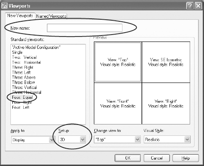
Note
Look at the Preview pane when you set up views. If you don't like the view or style used in each view, you can change them by selecting any of the four viewports and using the Change view to: or Visual Style: drop-downs.
When you click OK to exit this dialog box, you have four viewports, each of which has zoomed to the extents of the viewport. Click in the isometric viewport, and type
ZOOMand then0.6. Click in each plan viewport, and typeZOOMand then1. This is why you set limits earlier. This option of the ZOOM command zooms to the limits, which are a little larger than the object you're creating. After you finish, the three plan views should be displayed at the same scale and look like this: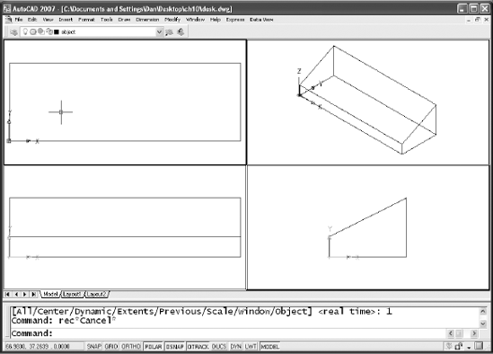
Go back to the Viewports dialog box, and give this configuration of views a name. You'll be switching to a full screen to work on any model, so it's much more efficient to restore named viewports than it is to reconfigure them. Notice that the Top, Front, and Right viewports have a plan view of a different UCS. That's the result of creating a 3D setup in the Viewports dialog box. When you make one viewport active and start to draw, you're drawing in the UCS that's active in that viewport.
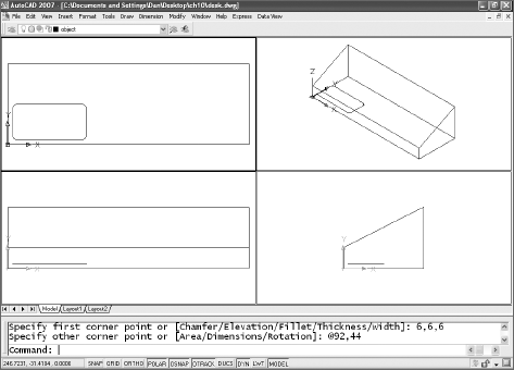
Draw the shape of the pockets, and go through the steps that follow to extrude them the way you extruded the overall shape of the organizer. These shapes have to be closed polylines, circles, or regions. Because the RECTANGLE command creates a closed polyline, use it to create all but one of the shapes. Because the pockets don't go all the way through the object, start the rectangle at a Z-axis value of 6. Because the first rectangular shape is filleted, start with a rectangle that has fillets, and draw it in the Top view. You created the original shape at 0,0, so you can type
6,6,6to start this rectangle. (You could also temporarily set ELEVATION to 6 and eliminate the Z coordinate, but there's always the danger that you'll forget to set it back to 0.)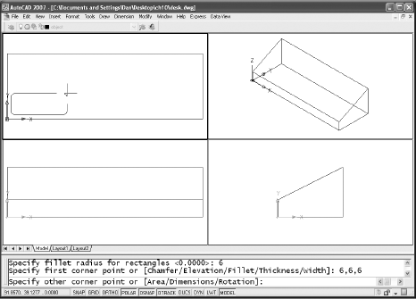
Note
You may try to extrude a polyline that looks closed and get an error. Use the PEDIT command, select the polyline, and see if you can close it. In AutoCAD 2007 you can extrude an open polyline, but the result is an extruded surface, not a solid.
Notice that once the shape is created, you can see it in all four viewports. The Front and Right views show that the rectangle is above the XY plane. If you select the rectangle, it appears highlighted in all four views. You can switch viewports after selecting an entity or starting to create a new entity, but the UCS of the original viewport remains active until you complete the action.
Note
Take advantage of the fact that a polyline is a 2D entity. Once you establish the first vertex, the entire polyline is on the same plane, so there is no danger of drawing something that looks fine in one viewport but extends to a different Z coordinate. If you want a 3D polyline, use the 3DPOLY command.
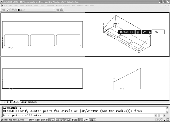
After you draw your first rectangle, copy it twice for the other pockets of the same size. Start the slot by drawing a circle. I used the From osnap in the graphic and typed the offset from the selected corner. Note that this circle should also be at an elevation of 6, so the Z coordinate must be 6.
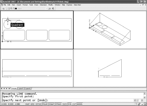
Finish the slot by copying the circle 50 units to the right. Add lines between the quadrants of the two circles, trim the circles, and then combine the resulting arcs and lines into a single closed polyline using the PEDIT command.
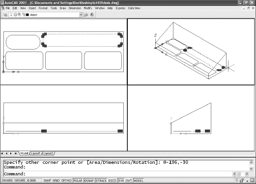
Add the last rectangular pocket. The graphic shows the results of selecting the rectangle in one viewport. It's highlighted in all three. Don't be confused by this. You're looking at the same objects in all four viewports, just from different views. If you erase the rectangle in one viewport, it won't exist, so it won't be displayed in any of the others.
Now that you have all five closed polylines, you can extrude each of them into a solid:
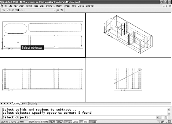
Use the EXTRUDE command, and make sure the resulting solids extend beyond the sloped surface of the solid. It doesn't matter how far beyond they go, because you're going to subtract them from the largest solid. You can select all of the objects when prompted for a selection set by the EXTRUDE command and extrude them as a group.
Use the SUBTRACT command and select the largest solid when prompted to "Select solids and regions to subtract from..." SUBTRACT is one of the Boolean commands. The others are UNION and INTERSECT. They're used to create shapes from more than one solid or region. You'll see a use for INTERSECT later in the chapter, but the other two are self-explanatory. When you use SUBTRACT, though, you must read the prompts carefully.
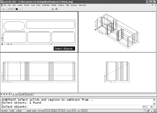
After you select the largest solid, you need an

Note
The SUBTRACT command can deal with two kinds of objects: solids and regions. Regions are 2D, but think of them as 3D objects with no thickness. You can use all three of the Boolean functions on regions in the same way you can with solids. Once you've created a region, you can extrude it, revolve it, or sweep it into a solid.
Finally (this won't take as long next time), when you're finished selecting objects, press
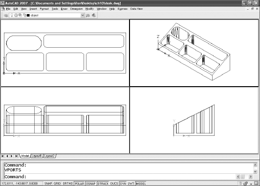
But wait a minute. You can see right through your model, but the mode shown in the previous graphic displays the organizer as a solid in the isometric view. You can choose to display each view of your model in a number of ways. Use the SHADEMODE (VSCURRENT) command, or the Viewports dialog box, or View → Visual Styles, and select any style you want. The next graphic shows the Conceptual visual style in the isometric viewport.
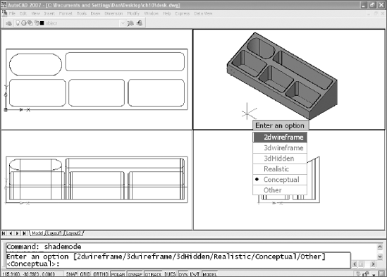
Why not set a Hidden, Conceptual, or Realistic style in all the viewports and leave it that way? Sometimes you can, but it's hard to edit a model if you can't see through it, so set the isometric view back to a 2D wireframe style Let's add some fillets to the corners of the organizer:
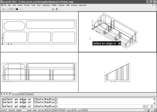
Use the FILLET command, and select the vertical edges that represent the four corners of the organizer. See why you had to set the isometric viewport back to 2D? The only viewport that displays the edges of all four corners is the isometric view, and you can only get to the back corner if you can reach through your model. Read the prompts carefully. FILLET doesn't work with a solid the same way it does with 2D entities, because you're selecting an edge for filleting on a model rather than two lines.
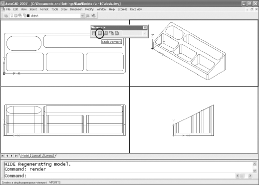
Now that you have the entire organizer modeled, you'll add some recessed text to it. This would be easier if your viewports weren't so small, so make one of them larger. Click in the isometric viewport, and display the Viewports toolbar. It has a button that creates a single viewport. Select it. (If you prefer typing, use the SI option of the command-line version of the VPORTS command. You could write a new command for doing this...if only you knew a little AutoLISP programming.)
You're making progress. Believe me, skilled 3D AutoCAD users apply these same techniques when designing models far more complex than this one. Although this model is simple, you can make it a little more interesting. I've been asked a few times how to add recessed or raised text to solid objects. The first time I did this, I drew each letter and created polylines that I could extrude, but I've discovered an easier method. In this tutorial you'll place text on the sloped surface, and then create 3D text with the useful, but flawed, Express Tool, TXTEXP. Follow these steps:
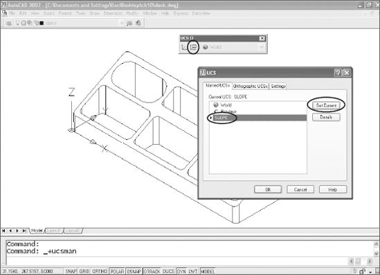
If you followed all the steps, you have a saved UCS for the sloped surface of the organizer. Make it current.
After you make the Slope UCS current, you can draw on it. But it's easier to place text when you're looking straight at the surface it's being placed on. Use the PLAN command.
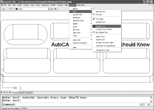
Now you're looking straight down on the sloped surface. Zoom in so you can see what you're doing, use the HIDE command to clear up the view, and then use the DTEXT or MTEXT command to place some text. Make sure the text is based in a TrueType font. I use Arial in this example. Make your choice, and then use Express → Text → Explode Text and select the text. If you don't have Express Tools loaded, you'll have to skip a few steps. You can still add some text as a 3D surface model though. Use an SHX font, and give it a thickness using the Properties palette.
Note
Express Tools aren't native commands and aren't supported by Autodesk. They don't always work flawlessly. Although it's worked well for me, there have been a number of reports of problems with the TXTEXP Express Tool, the command used here to explode the text. If the text disappears when you use TXTEXP, do a ZOOM Extents to find it and move it back into place. If it has been scaled, use the Reference option of the SCALE command to change it back to the correct height. Although the problems are annoying, they're a small price to pay for solid text if you ever need it.
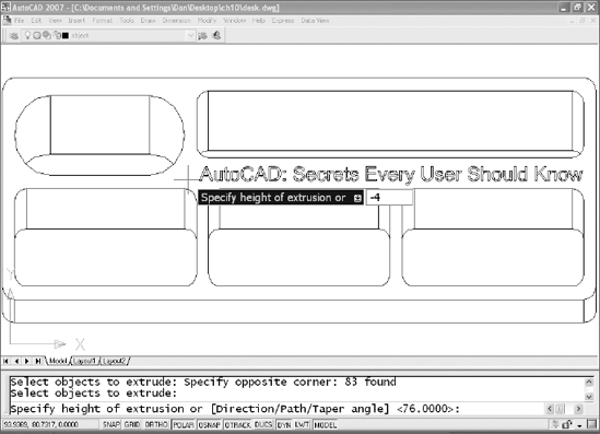
When the text is exploded, it's replaced with a large number of closed polylines. The closed polylines in the next image are about to be extruded negative four (−4) so they can be subtracted from the model. If you prefer, you can give the text a positive extrusion and union it to the model instead of subtracting.
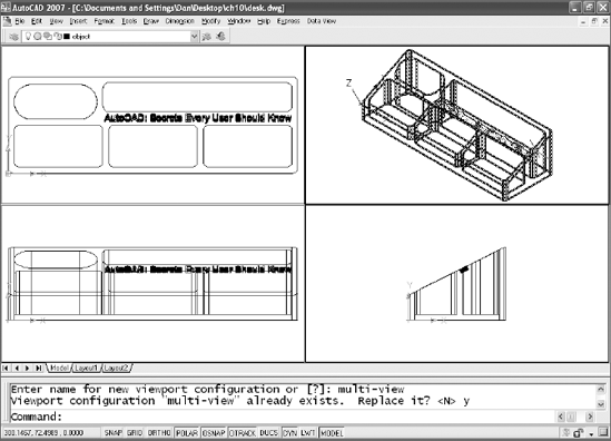
After extruding the closed polylines, subtract them from your model. You may find that you get better results if you UNION them together to form a single 3D solid first and then subtract the result from your organizer. The desk organizer should now be one object. Restore the group of four viewports and the organizer should appear as follows:
You've been able to change your view of the organizer with several methods:
Using the PLAN command
Setting up viewports
Selecting the SE Isometric button on the View toolbar
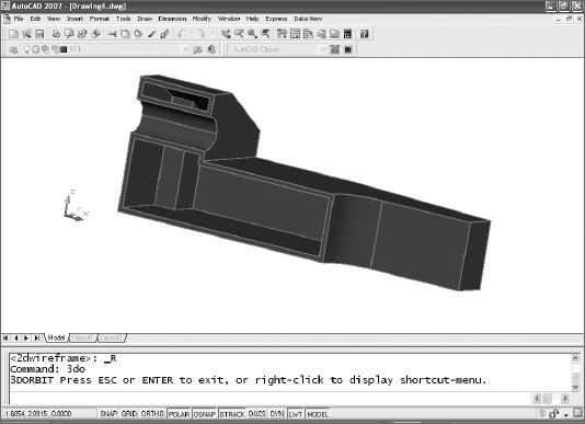
3DORBIT (the alias is 3DO) allows you to rotate your view (not the object) using the mouse. You can type that command or its cousin 3DCORBIT (continuous orbit), or find it on the AutoCAD 2007 menu using View → Orbit → Continuous Orbit. Earlier releases have it listed directly under View. Before you use it, make a few changes:
Create a single viewport for your isometric view.
Change the color of the model's layer to red (it looks better than white or black in this next step).
Set the visual style for the view to Realistic in AutoCAD 2007, or change SHADEMODE to gOuraud+edges (type an
O) if you're using an earlier release.Issue the 3DORBIT command, and play around with it. It's very intuitive. Hold the left mouse button while moving the mouse.
Right-click to bring up the 3DORBIT menu and change to a perspective view. In releases before AutoCAD 2007, you have to select the Projection option first to get to the Perspective View option, but in AutoCAD 2007 you can select Perspective directly as shown.
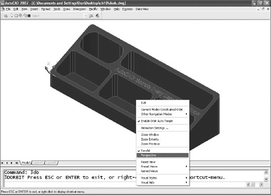
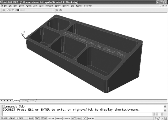
When you select Perspective and start moving the mouse, you're suddenly looking at a different view of the object.
If you want this organizer to look as though it's made of marble, glass, or wood, or if you want a graphic image applied to it, you can attach materials and render it. That process is very different in AutoCAD 2007 than it is in earlier releases. A lot of books cover the 3D features of AutoCAD 2007 thoroughly, and a little searching on the Web will bring up tutorials and other material.
I'll end this chapter with two examples, one architectural and one mechanical, of how to use existing geometry to generate models fairly quickly. The first example uses solid models to produce a perspective line drawing from existing elevations of a residence. The second example uses an existing multiview drawing of a mechanical part to create a solid model quickly. You don't have to invest a huge amount of time in learning 3D to get something worthwhile out of it.
When I first started using AutoCAD, I did a perspective drawing of a new church. At the time, I had a special drafting table for doing perspective drawing, but I wanted to see how well AutoCAD was suited for the task. So, I laboriously drew a plan view and elevations, and then set up a picture plane, horizon line, ground line, true-height line, station point, and three vanishing points in AutoCAD. In other words, I created a perspective drawing using the same tools I would have used for board drafting. Although I did use viewports to place the two vanishing points closer together, I'd have been better off at the board for all the time I invested. The building committee loved it...and asked for two other views. I declined.
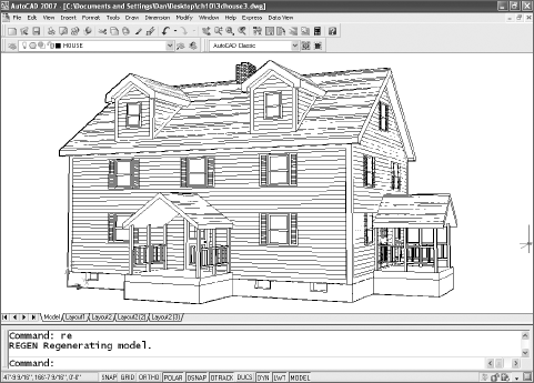
That experience prompted me to look into the 3D tools in AutoCAD. After a little experimenting, I realized that I could make a 3D mass model in AutoCAD and paste the 2D elevations I already had onto the surfaces. I couldn't get rendered output, but I could create quick perspective line drawings that would give people a much better picture of a building. If you have some existing 2D elevations, try this technique. It'll give you some practice with 3D modeling. and you may find that the return on your investment of time is much greater than the time required to create a rendered fly-around.
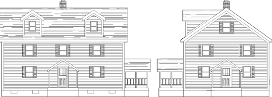
Let's start with the elevations. Suppose you've drawn a front and right side view of a residence, as shown in the simplified version here:
Use the following steps to create a 3D model using the elevations:
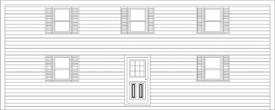
Create block definitions of the elevations. Don't use all the entities in each elevation; include only the entities that would be on a single plane of the final model. The gable-end block should show the siding and the windows, but not the roof overhang or the side of the dormer. The side of the dormer should be a separate block definition. The front elevation looks like this:
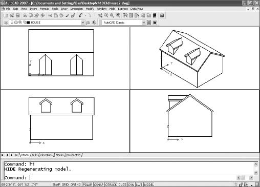
After you produce all the necessary blocks, create a solid model of the house and a separate solid model of the roof system. (You practiced with all the tools you need in the desk-organizer exercise.) Use the same dimensions you used for the 2D elevations. The house with a separate roof system is shown in the next image. It doesn't look like much right now.
Make the Front UCS active, and insert your front elevation onto the front of the mass model. Do the same for the other surfaces. The dormers are added in the next image.
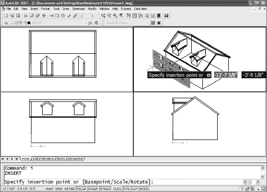
Set each UCS for placing the other 2D blocks. The gable-end block requires a Right UCS. So does the near side of the dormers. If you want to paste elevations on the back of the house, use the Back UCS. The next image shows the front block being placed.
Create a UCS for each roof plane using the 3P option of the UCS command, and add a hatch pattern (I use AR-RROOF at a scale of 24) to simulate roofing. To place the hatch, create a closed polyline, and use Add: Select Objects to select the boundary—picking a point inside a boundary doesn't work well in 3D. For the roof, outline the area you want to hatch with a rectangle that starts at the origin (0,0,0) of your roof UCS. After adding the porch details and perhaps a foundation and chimney, you have something similar to the next image.
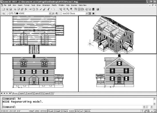
You have two choices for getting a perspective view: 3DORBIT or DVIEW. Because you're familiar with creating a perspective view with 3DORBIT, use that method in a single viewport. Now you have a credible perspective line drawing that you can plot and use for presentation purposes. Or, you can plot it out and trace over it by hand to create a true hand rendering in a lot less time. Some clients still love to see those hand-made illustrations. The screen display may drop some lines, as it did in the next figure. That won't affect how this view plots.
Here's another strategy for using existing work, this one involving a mechanical part. You'll use a simple part here, but you can use this strategy to get a fairly complete model even with much more complex parts. I understand that a selling point used by one of the parametric 3D modeling programs is that it can convert 2D drawings into a 3D model, which implies that you can't do that in AutoCAD. Well, here's how you can, and I bet the resulting model is just as good.
Let's look at the three-view orthographic drawing with dimensions.
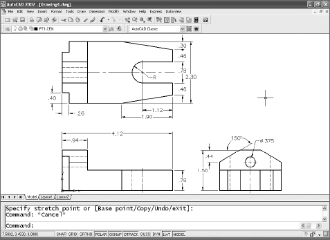
Use these steps to turn this 2D multiview drawing into a solid model:
Make the object layer current, and freeze all the other layers (-LAYER → F → * does that quickly).
Delete all interior features except the hole in the Right view, and then use the PEDIT command to convert the lines into polylines. (Or use the BOUNDARY command to pick a point and have closed polylines or regions placed on top of the lines.) Use the REGION command to convert the closed polyline and circle in the Right view, and subtract the circle from the polyline. This generates a single region with a hole through it. (If you're using AutoCAD 2006 or 2007, you don't have to use PEDIT to convert the lines into a closed polyline before creating a region.)
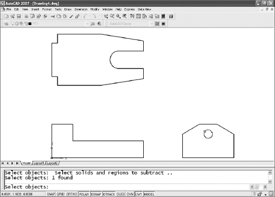
Switch to a SE Isometric view, and move each of the polyline profiles so the common origin of each is at 0,0,0. Note that for the Top view, this common origin is a projected intersection, while it is a corner for the front and right side views.
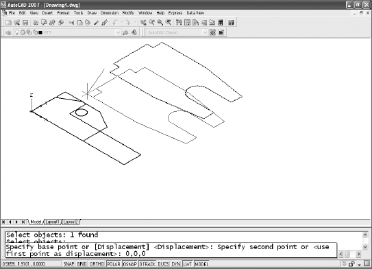
Use the ROTATE3D command to rotate the Front and Right profiles into their proper positions. You can leave the WCS current. Select two points to establish an axis for rotation.
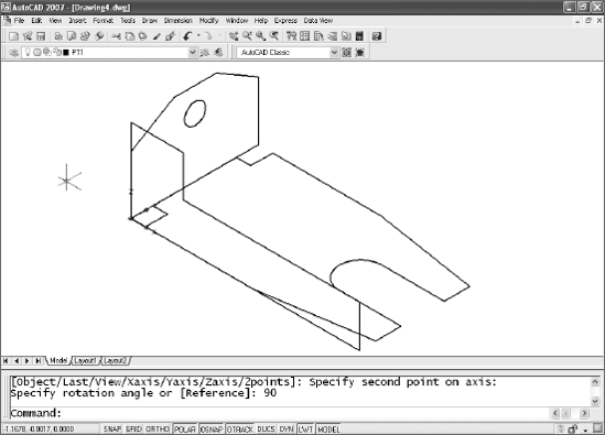
Extrude each of the profiles to its proper length. You can either type those values or select a point (two points prior to AutoCAD 2007). The Front view requires a negative value (−2.3). The result is something that defies physics: three solid objects occupying the same space at the same time. Not possible in the real world, but it works in AutoCAD.
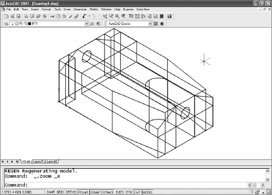
Now comes the magic. Use the INTERSECT command to create a solid from the mass that is common to all three objects. Select the objects, then
At this point, you've completed the model. If you want to edit it, you can do so in several ways:
Add fillets or chamfers to some of the edges.
Use SOLIDEDIT or the AutoCAD 2007 3D editing tools to modify faces or shell the object.
Use the SLICE command to cut though the model, using any three points.
Use the SECTION command to create a 2D section through any three points. The result can be moved off the object and hatched when creating views.
Place another solid and subtract that shape. A cylinder created with the CYLINDER command can be subtracted to create a hole.
Add features by using the UNION command to combine this solid with other solids.
Let's edit this model a little more:
Use
SOLIDEDIT→Body→Shell→ select the model →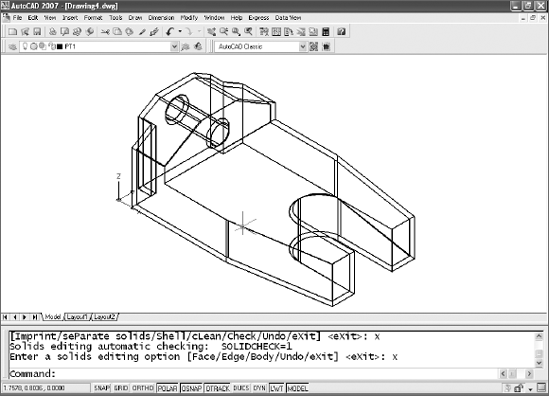
Let's slice it. You'll return to this point later, so use the Mark option of the UNDO command to place a mark before slicing the model. Use the SLICE command, and select the model. To cut it down the middle, select three midpoints, and select the piece in the background when prompted to
Specify a point on desired side or [keep Both sides] <Both>:.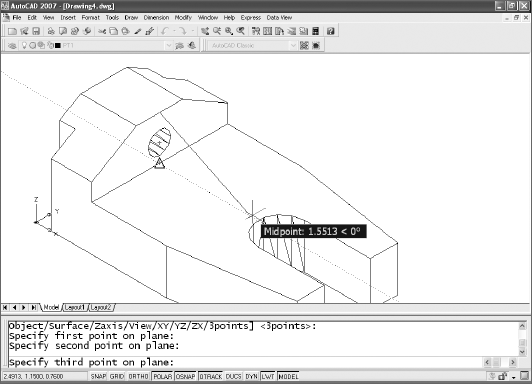
Change the color of the object's layer to red, and then use 3DCORBIT (3D continuous orbit) to display it realistically and move it around. Once you get it going, it appears to spin on its own. Press Esc to stop it, and ZOOM Previous to get back to your starting view.
Let's end this section by setting up a layout with four engineering views of the presliced model you just created:
Undo back to a point before you used the SLICE command but after you used SOLIDEDIT to shell the object. If you set a mark, type
UNDOand thenB.Set Visual Style to 2D.
Select a Layout tab.
Erase any viewports it contains.
Create a page setup for an A-sized sheet.
There are a couple of ways to set up drawing views of a model. You could use SOLVIEW, but in this example use
MVSETUP→Create→Create Viewports→2, and select two corners for the four views. Then, type0→0→Scale Viewports, select all four viewports, and press
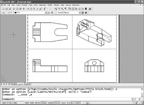
To finish, let's generate 2D profiles that display hidden linetypes in each of your views:
Activate the isometric view.
Type
SOLPROF, and then select the model in the Top viewport.Answer Yes to all three questions with
Repeat step 3 in each of the other three views.
Freeze the layer the model is on. Your sheet may not look any different, but you're no longer looking at a 3D model, you're looking at lines. Using the HIDE command will have no effect. What's the point? This gives you a line drawing that can be dimensioned reliably.
Look at the Layer Properties Manager. You have eight new layers, four of which start with PH, four with PV. The PH layers have the lines that are hidden and the PV layers have the lines that are visible. Note that in each viewport, six of these layers are frozen by viewport.
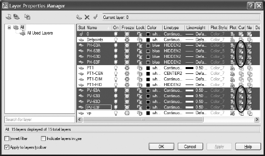
Change all the PH- layers to a Hidden2 linetype and a different color.
Change the lineweight of all the PV- layers to 0.4 or 0.5, and exit the Layer Properties Manager.
Your sheet should now look like this:
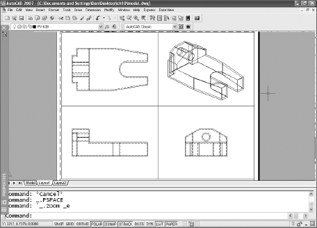
In each view, you have two anonymous block references (their names begin with *), one for visible lines and one for hidden lines. The isometric view doesn't display lines as hidden until you explode the block it contains, but you don't normally show hidden lines in an isometric view anyway; freeze that layer (or erase the block reference). The other views show the hidden lines correctly, but some of them require editing because they're so close to visible lines that they interfere with them. Explode the block to edit them.
In the following image, I erased the hidden lines in the isometric view, erased a few hidden lines that were too close to visible lines, and changed the linetype scale of two of the hidden lines so that they intersect properly with another hidden line.
Now that you understand coordinate systems and can create 3D models, try modeling something for fun. Maybe you can make a model of the interior of your home with the furniture in each room. The next time someone in the family wants to rearrange the furniture, do it on the computer first—it may save you some back strain and scratched floors. Or maybe you've got an invention in the back of your mind and want to know how it would look. Or, even better, create a model of something for the workplace, and show the people you work for how useful it can be. You may have to produce the first one on your own time, but your ingenuity may make you the one person your department can't live without.
I'll close with a handy tip sheet for 3D modeling.
Anchor your model by placing one corner or the center at 0,0,0.
Whenever you create a new UCS, save it with a logical name.
Use viewports in Model Space during the modeling process, and save the useful configurations with names. You can restore these named configurations in a layout using the MVIEW command.
Use the VIEW command to save views that you particularly like. It takes a little time to set up a perspective view that looks good, and specific views are hard to duplicate exactly using 3DORBIT.
Use the BOUNDARY command to quickly create closed polylines or regions.
If you want to move multiple solid objects into place as a group, don't union them together just for that purpose. Use the GROUP command. I've seen a lot of people make a single model using UNION, only to regret it later when they want to move or edit one of the original 3D solids.
If you use 3D models for 2D line drawings as you did in the architectural exercise, make all your blocks in the WCS and insert them onto the surfaces. Don't try to define blocks on the surface of a model. You'll run into pitfalls constantly.
When you're working with multiple models, place each one on its own layer.
If you plan to animate a model, don't UNION parts that move independently.
Create the most distinctive or complex shapes as closed polylines, and extrude them to reduce the amount of work you'll have to do later.
Don't overuse the commands that create primitive solids. You can use the CYLINDER and BOX commands for creating holes and getting a model started, but you seldom need the others if you extrude your most complex shapes from closed plines or regions. (I've seen the torus used to create an o-ring groove, though, so don't forget those other commands entirely.)
If your files start getting too large, consider the surface modeling commands. If they can do the job, they'll reduce your file sizes. If you have an assembly consisting of multiple models, bring them together in a master drawing as XRefs.
If you want to take advantage of all the 3D features, particularly in AutoCAD 2007, you may need to upgrade your video card.
There are modeling commands you didn't use in this chapter. Look at the REVOLVE command and the Path option of the EXTRUDE command in all releases.
In AutoCAD 2007, look at SWEEP and HELIX, which can be used together to create springs or threads by drawing a cross section and sweeping it along a helix.
Also in AutoCAD 2007, try the POLYSOLID command. It's like a 3D polyline, creating slabs with straight lines and arc segments. It can also be used to convert existing 2D objects into solids.
You can get volume information about a solid with the MASSPROP command.
DISPSILH determines how models will look when the HIDE command is used. If you set DISPSILH to 0, tessellation lines are shown; if you set it to 1, they aren't.
The ISOLINES variable controls the smoothness with which solids are displayed on the screen.
The FACETRES variable controls the smoothness with which models are displayed when rendered. It's multiplied by the setting for VIEWRES. The higher you set both variables, the smoother curved objects look when you render them. (VIEWRES also controls the screen resolution of arcs and circles, which are unaffected by FACETRES.)
The UCS command has some options that you didn't use for the exercises in this chapter. The most useful is the option that lets you rotate the current UCS around any axis by typing X, Y, or Z at the UCS prompt.
Note
Speaking of rotating the UCS, you'll see the right-hand rule discussed in a lot of references as an aid to determining whether an angle should be positive or negative when working in 3D. Instead of puzzling over the rule, try typing in a value to see if it goes in the right direction. If you guess wrong, there's UNDO, the most frequently used command in AutoCAD (at least, by me).
The 3DORBIT command can be used to set clipping planes for viewing objects. You can hide the portion of an object in front of one plane and behind another so you can work more easily on the interior of a complex model.