It's impossible to imagine AutoCAD without blocks. They've become as fundamental as drawing lines and circles. When external references were introduced, they were like super blocks that could span multiple drawings, and before long most of us found them nearly as essential as blocks. Now that tables have become internal spreadsheets, and fields can be used to place adaptable text, the process of annotating designs is more efficient than ever. These indispensable annotation tools are now commonplace, but there are times when they can still be baffling.
In this chapter, I'll address the fundamentals of blocks, the appropriate use of the WBLOCK command, and the management of external references. I'll make suggestions for managing symbol libraries, provide an overview of the process of attaching attributes to blocks, and demonstrate how to extract data from blocks in a drawing using two different approaches.
Blocks
Editing Blocks
Managing Symbol Libraries
Adding and Extracting Attributes
External References
Tables and Fields
If you ever did any board drafting before the advent of computer aided design, you undoubtedly used a number of green plastic templates containing cutouts of standard symbols used in your discipline. Templates made drafting more efficient and more uniform. Blocks are often compared with those handy templates, and in some ways that comparison is apt—but not entirely. Blocks and the other annotation tools in AutoCAD have far more value than those green templates ever did. Using a computer for design is more about creating a geometric database than it is about plotting lines. Once you've inserted a block definition, it carries information that can be extracted from the drawing's database. You can find out how many times a block definition was used, where it was inserted, what scale was used. You can attach attribute information to block references and extract that information as well.
Let's quickly review some fundamentals about blocks that you may have overlooked, and then look at some related commands and functions, particularly the misunderstood WBLOCK command. After that, I'll try to straighten out the visibility-control problem you may have encountered with blocks that include entities from different layers.
Before I begin the discussion of blocks, I want to run down a list of some important basics. Knowing this information will help you use blocks more effectively:
A block definition cannot be seen in a drawing.
A block reference can be seen in a drawing, but only if
The block reference is on a layer that's turned on, and thawed.
The view on the screen includes the area that contains the block reference.
You actually selected some entities when defining the block.
The original layers of the entities used to create the block are turned on and thawed.
Note
Did you know that a block can be defined with no entities in it? You can insert it just like any other block, but you won't see anything, because the block consists of...nothing except an insertion point, scale, and rotation angle. This usually happens when a new AutoCAD user tries to insert a block definition using the BLOCK command instead of the INSERT command, accidentally creating a block from nothing. I've known experienced users who create an empty dummy block that they plan to redefine later. If I did that, I'd include at least one entity.
Blocks can be inserted directly only in the drawing in which they're created.
AutoCAD DesignCenter allows you to easily bring block definitions from a saved drawing into your current drawing.
A reference to block definitions from saved drawings can be placed on a tool palette (see Chapter 3).
Any drawing can be inserted into any other drawing, at which time it becomes a block in that drawing.
Blocks can be inserted anywhere in 3D space, using coordinates or osnaps, at any scale, even one that's different in each of the X, Y, and Z axes.
Blocks can be mirrored about any axis when they're inserted by giving a negative scale factor for that axis.
A block can be inserted as a single entity or broken down into component entities upon insertion. You do this by checking the Explode box in the Insert dialog box or by placing an asterisk (*) before the name of the block when it's inserted from the command line (for example,
*block).Although a block reference can be broken into component entities using the EXPLODE command, don't do it unless you have a good reason. What would a good reason be? Sometimes you may use a block definition to move a group of entities from one location to another—from the Model Space tab to a layout, for example. In that case, you aren't really defining a symbol, so you explode the result to get the entities back.
A block reference that has different X, Y, or Z scale factors can't be edited using REFEDIT.
A block that has been inserted using the MINSERT command can't be exploded in any release. Unless you actually do want to prevent an array of block references from being edited, you're much better off inserting one block and using the ARRAY command to create others.
Entities within a block that resided on layer 0 when the block was defined take on the visible properties of the layer onto which the block is inserted.
Entities within a block that resided on a layer other than 0 when the block was defined always retain the properties of their parent layer.
When exploded, a user-defined block's entities return to the layer on which they were created.
A dimension is an anonymous block. When exploded, its entities are placed on the layer onto which it was inserted. Earlier releases of AutoCAD would place these entities on layer 0.
A hatch pattern is an anonymous block. When exploded, its entities are placed on the layer onto which it was inserted. Earlier releases of AutoCAD would place these entities on layer 0.
A block can be redefined after it has been inserted. There are several ways to do this:
You can use the Block editor as of AutoCAD 2006.
You can use REFEDIT as of AutoCAD 2002.
The BLOCK command can be used to define a block with the same name.
The block definition can be replaced with a drawing of the same name using the Insert dialog.
The block definition can be replaced with any drawing using the -INSERT command and the syntax
oldblock=c:path
ewblock.dwg
.
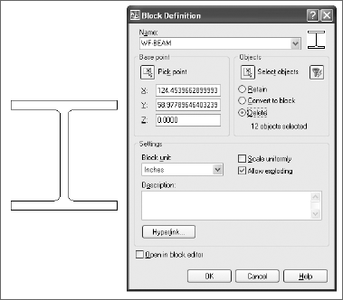
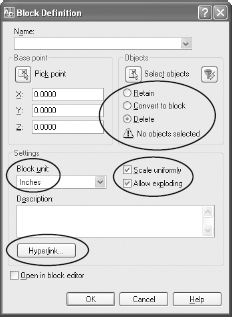
Figure 5.1 shows the current Block Definition dialog box familiar to all AutoCAD users, but there may be a few things you haven't noticed. The top part of the dialog allows you to name a block definition, select a base point (don't forget, or else 0,0,0 will be used as the base point), and select objects. Once the block is defined, you can then control what happens to the entities you selected:
Retain Defines a block from the entities but leaves them in the same state.
Convert To Block Creates a block reference at the same location as the objects you selected, and deletes the objects.
Delete Does what the BLOCK command does at the command prompt—throws the entities away once the block is defined.
The Settings area of the dialog box has two newer options. If you select Scale Uniformly, the block definition can't be scaled independently in the X, Y, and Z axis. If you clear the box labeled Allow Exploding, no one can explode a block reference created with this definition.
The Hyperlink button lets you include a link to a file, layout tab, model tab, or website as part of the block definition. When the block is inserted, it includes that link. To follow it, you hold down the Ctrl key and left mouse button.
If the units identified in the Block unit: pane differ from the units set for the drawing in the Units dialog box, the block will be scaled accordingly when it is inserted. If you define a block with units set to meters, and insert it into a drawing in which units are set to millimeters, the block will be scaled by 1000 when it is inserted.
If you find blocks confusing, it may be because people often use the term block to refer to two different concepts: a block definition and a block reference. A block definition is the equivalent of a stamp with your name on it that you keep in your desk drawer. It exists, but your name isn't yet stamped on anything. Once you take out the stamp, ink it, and press it onto a sheet of paper, you have the equivalent of a block reference.
WBLOCK isn't a block command; it's a save command. I've fielded countless questions over the years stemming from confusion over this command. I wish it had been named something with the word save in the name, but it wasn't. Just keep in mind that you're creating a new drawing file whenever you use this command, and it isn't necessary to use this command to create a file that you intend to use as a symbol in other drawings. You can use any drawing file as a symbol.
Note
There's no WBLOCK entity in AutoCAD. Users who say they made a wblock might as well tell you they made a save. That may make sense in some sports, but not in AutoCAD.
The great utility of the WBLOCK command is the flexibility with which you can create drawing files from part of an existing drawing. Let's say you want to create a separate drawing file using only a portion of an existing drawing file. There's no need to erase objects you don't want in the new drawing—just use the WBLOCK command. There are three ways to use the WBLOCK command to partial-save a drawing (hey, PSAVE might have been a good name). Let's look at each one:

Entire Drawing Selecting this option results in a drawing that has all the entities in the current drawing and everything needed to support those entities. Because unused layers, dimension styles, text styles, and block definitions aren't saved with the drawing, its size is reduced as much as possible.
When using the command-line version of WBLOCK, type *

Objects I've seen people erase a lot of entities in a drawing so they can save those that remain as a separate drawing. They then get all the layers, styles, linetypes, and block definitions even if those aren't related to the objects they want to save. WBLOCK creates a drawing file from only those objects you select, and it includes only the elements of the drawing necessary to support those objects.
Use any portion of a drawing to create a new drawing file by selecting entities directly and identifying an insertion point. Using the command-line version of WBLOCK, press the Enter key when prompted for a block name. Now entities can be selected in the same way they are for the BLOCK command. When you use the command-line version of WBLOCK, the selected entities are erased. To get them back, use the OOPS command.
Nesting is a concept, not a command. It describes the process of using existing block references as entities in a new block definition. There appears to be no limit to how deeply blocks can be nested. I've tried creating an absurd number of nested levels, just to test the theory, and so far I haven't found a limit.
Why would you want to create a block definition from existing insertions of block objects? For starters, you may want to be able to change one aspect of an inserted block but not others. If that aspect is represented by its own block definition, redefining it will change its appearance everywhere it appears, even if used as a nested block in another block definition.
Note
Before adding attributes to existing block definitions, you may want to insert the desired block without attributes, define the attributes, and then create a nested block from the block reference plus the defined attributes. Now you'll have two versions of that symbol—one with attributes, one without. If you want to change the appearance of the block without affecting the attributes, you can redefine the base block. See the next section for more information on adding attributes to blocks.
When one drawing is inserted into another drawing, its insertion point is normally 0,0, but you can change that with BASE. The BASE command redefines the insertion point of a drawing from 0,0 to any coordinates you type in or select. If you expect to use a drawing as an inserted symbol in another drawing, it makes sense to be specific about where you want the insertion point.
The INSERT command has a useful dialog box, of course. It allows you to view a list of all block definitions, or other DWG files, and select one you want to insert. But you can also use INSERT at the command line by placing a minus sign in front of it when typing: -INSERT. This is helpful in creating AutoLISP programs that insert a drawing into another drawing.
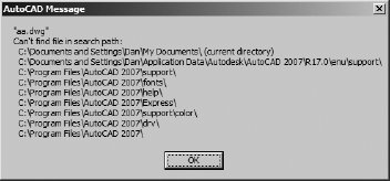
There's another, more unusual use for the command-line version. Typing -INSERT followed by a nonexistent block name gives you a quick indication of the search path AutoCAD is currently using, because it lists all the places it looked for the nonexistent block definition you specified, in order. The first place AutoCAD always looks for a block definition is in the drawing itself. The rest of the list contains the directory where the drawing is currently saved and then the AutoCAD search path specified in OPTIONS. See Figure 5.2.
Note
If you try to insert a drawing using the command-line version of INSERT, you may not get what you expect. If the filename you specify is the same as an existing block definition, the existing definition is used instead of the drawing you specify. Unlike the warning you get with the INSERT dialog box, AutoCAD uses the existing definition without asking if you really mean it.
A brand-new space first appeared in AutoCAD 2006. In addition to Model Space and Paper Space, we now have what I think of as Block Space. Block Space is an editor that makes defining and editing blocks much easier, because you can use all the standard AutoCAD editing and object creation commands, and the odd-colored background never lets you forget which space you're in.
If you can't stand using the block editor, you can still use the standard Block Definition dialog box to create or edit blocks, or the REFEDIT command. Double-clicking a dynamic block won't bring up REFEDIT by default, but you can change that, if you want.
Note
Double-clicking a block can result in different actions, depending on whether the block has included attributes. If it's either a standard block or a dynamic block reference that has attributes, the Enhanced Attribute Editor opens. If it's a block reference without attributes, the block editor opens. Prior to AutoCAD 2006, double-clicking a standard block without attributes opened REFEDIT. You can change any of those double-click behaviors, as of AutoCAD 2007, in the CUI dialog box.
One thing I've always appreciated about Autodesk is that legacy behavior doesn't usually change in new releases of AutoCAD. This reduces, but doesn't eliminate, the surprises that can confront you went upgrading to a new release. Even though there are now two other tools for editing blocks, the old fashioned method still works just fine.
For years you've updated blocks using the BLOCK command. You still can. Just draw a new symbol, use the BLOCK command, and define a new block with the same name as an existing block. It may save time to insert the existing definition, explode it, and then edit the resulting entities. The redefined block immediately updates any block references that have already been inserted into the drawing. This allows you to globally edit even a scaled or MINSERTed block. Redefining a block in this way affects only one drawing file.
You can still redefine a block or an XRef using REFEDIT, if you prefer, either with the Refedit toolbar, or by typing REFEDIT at the command line. The result is the Reference edit dialog box, which displays the block and a tree showing nested blocks. You must select the level you want to edit and then select the objects within that definition that you want to change. Don't close the Refedit toolbar using the X in the upper-right corner; instead, click the third button to discard changes or the last button to save them. If you get a message indicating the objects are "not in the working set," you're still in Refedit: Reopen the toolbar (type REFEDIT at the command line), and then select Close Reference or Save Reference Edits.
You can also redefine a block by replacing its definition with that of an existing drawing file using the -INSERT command. When you're prompted for the block name, type oldblock=newblock. This replaces an existing definition named oldblock with a drawing named newblock.dwg. Don't forget to include the path along with the drawing name.
If your old block definition and the new block definition have the same name, you can redefine the existing block using the Insert dialog box. If you try to insert a drawing with the same name as a block that exists in the drawing, you're asked whether you want to redefine the old block. Say yes, and all block references are redefined.
When you create a block definition using entities that reside on layer 0, those entities take on the properties of the layer onto which they're inserted. They also return to layer 0 if the block is exploded. The entities that reside on any other layer always have the properties of that layer, even when inserted onto a different layer. This creates a block whose visibility is controlled by more than one layer: the parent layers and the host layer.
Note
I use the terms parent layers and host layer quite a bit in this discussion. By parent I mean the layer on which entities reside when you select them to define a block. By host I mean the layer onto which you insert a block entity. These aren't official AutoCAD terms, so they're unlikely to be used by others when discussing AutoCAD.
The parent layer where block entities were located when the block was defined (if not layer 0) control color, linetype, and object visibility. If you freeze or turn off the parent layer, those entities in the block that are on that layer won't be visible. This can be confusing, because it's possible to change the visibility of only part of an inserted block object.
The host layer onto which a block is inserted controls entities in the block as follows:
If you freeze the host layer, those entities that reside on the parent layer aren't visible. However, entities on the parent layer aren't affected by turning off the host layer.
If you lock the host layer, the block reference can't be erased, copied, moved, rotated, or scaled when the host layer is locked. However, if the block definition is changed, any block inserted onto a locked (or even frozen) layer is also redefined.
Note
Layer 0 is like no other layer, and in my opinion it should be reserved exclusively for entities you place for the purpose of creating a block definition. That way you can leave layer 0 on and thawed at all times. In pre-2006 versions of AutoCAD, placing dimensions, which are anonymous block definitions whose entities originally reside on layer 0, can be tricky if you have frozen layer 0 and are working in a layout. They won't display until you select their location.
Note
This selective control of the visibility of entities within a block may seem annoying and cause some confusion, but it offers the possibility of a creative unintended consequence. I know of one user who created an elaborate system of nested blocks using entities from various layers so that he could freeze and thaw layers to selectively display the layout of a large mill by location, system, or both. When he combined this with named views and a few menu macros, he had an impressive key system for viewing his drawings.
Should you use dynamic blocks? Maybe.
Think twice before converting a perfectly usable existing block-library system into dynamic blocks. Doing so will take a lot of time, and other offices with whom you work may still be using a pre–AutoCAD 2006 release and have no way of utilizing the dynamic properties of blocks. Not all block definitions benefit from adding parameters and actions. I recommend the following:
Continue to use your current block-management system.
Look for places where a single block definition can replace multiple versions of the same basic symbol.
If a dynamic version seems useful, create one using the existing block definitions by giving each a separate visibility state.
Recognize the limitations of using dynamic blocks with earlier releases.
Let's discuss dynamic blocks further in this section.
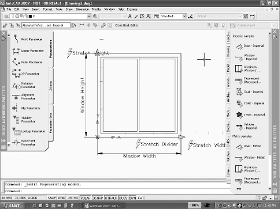
AutoCAD ships with many dynamic blocks already referenced onto Tool Palettes. You should start by inserting one of them and then double-clicking it to enter the new block editor. All the things you see floating around the block geometry are objects representing parameters or actions. Because they're objects, you can select them and view or change their properties in the same Properties palette as other objects. Figure 5.3 shows a stretch action.
Because it's so new and so different, let's go over the basics of creating these blocks with just enough information to get you experimenting.
Actions are things that happen and are usually represented by command names; parameters are the values that control those actions. In Figure 5.3, the window block can be stretched to change the window's height. The action Stretch is controlled (or constrained, to be more inventor-like) by the Linear parameter window height. To create this image, I added two objects to the window in the block editor: a Linear parameter and an action that's attached to that parameter.
Create the entities you want displayed when a block is inserted the same way you've always created blocks: Just draw something. If you have a block, insert it. If not, open the Edit Block Definition dialog box and start drawing. The Help system contains a good overview of the new dynamic-block features, and you can also find some very good papers online at www.autodesk.com.
There are a number of strategies for creating and managing symbol libraries. In the distant past, symbols were often added to a tablet menu and picked directly from the tablet with a puck. I occasionally bump into someone who still uses a tablet, but not often. In the not-so-distant past (pre-CUI), an image menu containing slides of blocks was often created and used on the screen as part of a pull-down menu. Creating such an image menu required customization of the ACAD.mns file. AutoCAD's DesignCenter offers a much better alternative. Use it to view and insert blocks from any drawing, including the current drawing if it has been saved.
It is important to have complete symbol libraries that contain blocks that are accurate and easy to use. In this section I'll discuss different strategies for creating and managing your symbol libraries. Which of them you use is up to you.
Block symbols should be created actual size most of the time. In other words, a block that represents a washing machine should be drawn the size of a specific washing machine. A schematic block—like a resistor symbol or a duplex receptacle symbol—should also be drawn full-size, but that means something a little different. Because the same symbol is used to represent objects whose actual size differs, draw the schematic the size you want it to measure when it is plotted. If, for example, you want a duplex receptacle symbol to be .25″ when plotted, define the block using objects that are .25″. When you reference the block on a floor plan, scale it to the reciprocal of the plot scale used. It will be the correct size when plotted.
Note
It's tempting to use symbols created by someone else. If they work for you, fine, but I think you're generally better off making your own symbols, unless they're from a manufacturer's site and represent a specific model. Even then, manufacturer's symbols often have too much detail to plot correctly. I've seen people grab a generic stove symbol from DesignCenter only to discover later that the size didn't match the real stove being used.
Sometimes it makes sense to use what is known as unit sizing, but a lot of users overdo it. Unit sizing involves defining each block to measure 1 unit × 1 unit. When inserted, the block is scaled in the X, Y, and Z axes to its actual size. In theory, this allows you to use a single block definition for, say, many different sizes of refrigerators. Some symbols lend themselves to unit sizing—a simple door symbol, for example—but most don't, because elements within the symbol get distorted when the scales are different for the different axes.
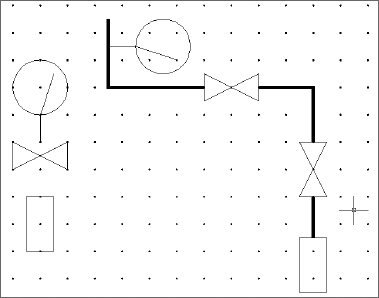
Here's one of the few uses I have for AutoCAD's SNAP and GRID commands. When I use a snap, I always set a grid that's twice as large. It's a lot easier on the eyes. For schematic symbols, I set a logical snap increment like 0.1 to draw each symbol, making sure insertion points land on a snap. Once I've drawn all the symbols for a schematic diagram using the logical snap increment, I set the same snap increment when I draw a schematic diagram that uses the symbols. I plug them into a grid and connect them with lines that end exactly where I want them—a little like using Lego building blocks. See Figure 5.4.
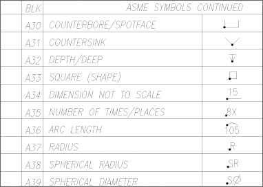
Once you've defined standard blocks, place references to them on a tool palette as described in Chapter 3. You may want to create a reference drawing by inserting block references into a grid and adding a dot (DONUT) at each insertion point. Include the name of the block, and print the drawing. Now it can be used as a reference in a CAD standards binder. Although it's useful to mark an insertion point with a dot, don't make the dot a part of the block definition. Figure 5.5 shows a partial example of an American Society of Mechanical Engineers (ASME) symbol library.
I've encountered three different strategies for managing symbol libraries. Any of them can be used effectively, and some users will combine them, particularly if they work with a number of different clients or contractors and use symbols provided by them.
Create a drawing file for each symbol.
Include all symbols in each template file used.
Group related blocks into separate library drawings.
I prefer the last option, partly because of how easily the related symbols can be placed on a tool palette, but you should use whatever system makes the most sense to you.
When creating a drawing file for each symbol, you don't use the BLOCK command. Instead, you create a drawing file, place the insertion point of your objects at 0,0, and store each symbol in a subdirectory as a separate drawing file. When you need it, insert the drawing from that directory into any drawing. Once a drawing has been inserted, it becomes a block within the host drawing. Because you only insert symbols that you use, this method results in a host drawing with no unused block definitions.
Many offices use this system, particularly for standard details that are used in a lot of projects, but it does have a drawback: Storing all those drawing files takes a lot more space on the drive. Any individual drawing file requires a minimum amount of hard drive space, so 12 blocks stored as individual files take up more space than one drawing containing the same 12 block definitions. Because of this, and because DesignCenter and Tool Palettes make block management much easier when a single DWG file contains a library of symbols, I don't usually recommend this practice.
Another method for managing symbols libraries is to place all block definitions in your template drawings. When you start a new drawing, begin with the template drawing, and you have all your standard blocks in the drawing you're working on.
The drawback to this method is that your drawing files become much larger and must be purged when you're done if you want to reduce their size. If you don't purge all the unused block definitions, every drawing you produce will be larger than it needs to be. I recommend this practice only for those block definitions that are used in every drawing, such as title blocks and borders.
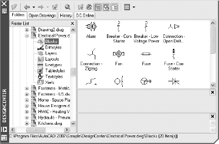
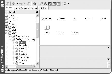
My recommended method for maintaining symbols libraries involves creating blocks grouped into library drawings. This is the practice that I find is most common. Place all related block definitions in separate drawings that contain only block definitions. If you use a large number of symbols, break them into categories and create a DWG file for each category. You can then use DesignCenter to create a tool palette that contains all the block definitions from each symbol-library drawing or to load individual blocks from the symbol drawing into your current drawing as shown in Figure 5.6.
If you want to bring all block definitions from one drawing into another, insert the entire drawing and press the Esc key when prompted for an insertion point. All the block definitions (and all other user-defined elements) become part of the drawing. This can result in a lot of unused block definitions, layers, dimension styles, text styles, and so on. If so, you can use the PURGE command to eliminate the unused objects.
There's another serious drawback to this method. If you have a naming conflict between any element of the host drawing and the drawing being inserted, the host drawing wins.
This causes a problem if you use the same name for different block definitions in the two drawings. Your changes are discarded if the host drawing contains different definitions. For that reason, I don't recommend inserting a drawing to get the block definitions. DesignCenter is a more efficient method, and you can see what the blocks look like before you insert them.
Note
If you have block definitions in a drawing that was created with an early release of AutoCAD, the blocks may not all display in DesignCenter. Icons representing blocks weren't added to drawing files before DesignCenter appeared. Even if you've edited the drawing in a release that contains DesignCenter, block icons appear only for blocks defined in the newer release (see Figure 5.7). To create icons, open the old drawing, and run the BLOCKICON command. Select all blocks by accepting the default when prompted to Enter block names <*>.
When defining a block, you can include attributes. Attributes are text-based information categories that are carried with the block definition. You provide the value for the attribute when the block is inserted. This information can be any property of the block that can be given a value consisting of a text string or number. For example, a single symbol for a tree can include attributes indicating the species, size, cost, age, supplier, and so on for that particular tree.
Note
Attribute definitions are meaningful only if they're used as part of a block definition. By themselves, they have no utility—at least none that I've come across.
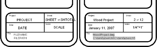
One of the most common blocks to create with attributes is a standard title block. Any information that changes from drawing to drawing should be added as an attribute. When you insert the block, you can provide the values for attributes like project, sheet number, scale, and date. In addition to attributes, you can add fields to title blocks describing information like the filename or path, as shown in Figure 5.8.
Figure 5.8 shows two views of a title block. The left view displays the entities used to define the block; the right view displays an insertion of the block definition. The entities used to create the block include attribute definitions with the following tags:
PROJECT The tag for the project name. It's a visible attribute, as are all the others shown here.
SHEET The tag for the number of this sheet. If this drawing was part of a sheet set, this value could be displayed as a Field.
SHTOTAL The tag for the total number of sheets. Notice that it overlaps the border of the title block. That's OK, because the attribute tag is replaced with a value that has fewer characters, as shown on the right.
DATE The tag for the date. It's possible to use a field for this value, if the date is either the date the drawing is plotted or the date the drawing was created. In this case, the value must be provided by the user, because it represents a completion date.
SCALE The tag for the scale used to set up the main floating viewport on this sheet. The value must be entered by the user.
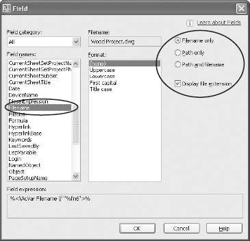
FILENAME The tag for the name of the current file. Its default value is a field that's used as an attribute. Because it's a field, its value changes if the default drawing name is changed. Fields are displayed with a mask when inserted into a drawing, as shown on the right. The mask won't plot. It's there for your reference.
Note
If you use the SAVEAS command with a different filename or path, you redefine the default values. The new values will be displayed by the Filename field.
FILEPATH The tag for the location of the drawing file. It's the same field as used for FILENAME, but with different properties, as shown in Figure 5.9.
Attributes can be defined to either appear as part of the drawing or be invisible. Either way, the information attached to a block can be extracted from the drawing into a file for use in another application, generally a database program like Access. The file into which you extract the attribute values can be an ASCII text file or an MDB file (Microsoft Data-base file). Attributes can also be extracted directly into an AutoCAD table.
The commands listed in Table 5.1 are used to create and modify attributes (consider making aliases for them in your ACAD.pgp file). Those commands that begin with the letter E (for extended) are used to manage and extract block attributes manually. Those that begin with the letter A can be used manually but can also be used in scripts and Lisp routines when you're automating procedures that involve attributes.
Table 5.1. Creating and Modifying Attributes
COMMAND | MEANING | PURPOSE |
|---|---|---|
ATTDEF | Attribute definition | Dialog box for defining attributes for use in a block definition. |
-ATTDEF | Attribute definition | Command-line version of ATTDEF. |
ATTDIA | Attribute dialog | Variable that determines whether a dialog box or the command line is used to complete attribute information when inserting a block. |
ATTDISP | Attribute display | Controls the display of attributes. ON displays all attributes, even invisible ones. OFF hides all attributes, even visible ones. Normal displays them as defined. |
ATTEDIT | Attribute edit | A dialog box to be used to edit attributes one block at a time. |
-ATTEDIT | Attribute edit | Command-line editor used to modify attributes after a block is created. -ATTEDIT can be used to edit blocks globally, rather than one at a time. |
ATTREDEF | Attribute redefinition | Redefines a block and updates associated attributes. Use this command if you have to add or remove attribute definitions in an existing block definition. Don't use the block editor, the BLOCK command, or REFEDIT for that purpose. |
ATTSYNC | Attribute synchronize | Updates all instances of a specified block with the current attributes. Use this command if you redefine a block containing attributes and want the changes to any attributes to be reflected in entities that have already been inserted. |
ATTREQ | Attribute request | Used to control whether you're prompted for a value when inserting a block that contains attributes. If it's set to 0, any block containing attributes is inserted with the defaults as set when the attributes were defined. Set this variable to 1 to allow prompts. |
ATTEXT | Attribute extraction | Dialog box for extracting attribute values into a text file. |
-ATTEXT | Attribute extraction | Command-line version of ATTEXT. |
BATTMAN | Block Attribute Manager | Allows you to manage existing attributes after they're defined. |
EATTEDIT | Extended Attribute Editor | Wizard used to edit attributes as of AutoCAD 2002. |
EATTEXT | Extended Attribute Extraction | Wizard used to extract attributes as of AutoCAD 2002. |
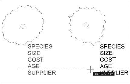
Attribute definitions are AutoCAD entities; they can be selected and used to create blocks, either by themselves or in combination with other entities. Usually they're used to annotate graphic symbols or complete title blocks, so they're generally used with other entities. Follow these steps to use them in blocks that also contain geometric entities (See Figure 5.10):
Create a symbol to which you'll attach attributes. For this example, use a couple of tree symbols as shown in Figure 5.11.
After drawing the symbol, turn it into a block without attributes and insert a reference into the drawing.
Note
Many users create a single block that consists of entities—lines, for instance—as well as the attribute definition. You can do that, but in this example I'm creating two versions of the same block definition—with and without attributes. The one without attributes is nested inside the other one. It's much easier to update the geometry of block references defined this way without affecting their attributes.
Add attributes with ATTDEF, and place them in the proper locations with the desired text style and height and the mode you want.
Note
It's easier to edit existing attributes than to add new ones to existing block definitions. Before defining a block, create any attributes you think you may ever need.
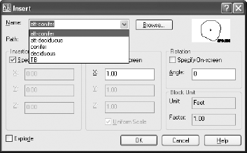
Make a new, nested block definition by selecting the inserted block and then the attributes. The new block must have a different name than the nested version, of course. You may want to add ATT as either a suffix or a prefix to the original block name. Use a prefix if you want all the attributed blocks to be listed together. Use a suffix if you want the two blocks to be listed together. For example, a symbol for a deciduous tree could be named deciduous with its attributed version named either att-deciduous or deciduous-att, as shown in Figure 5.12.
Note
When defining a block, if you use any method other than a single pick to select attributes, the order in which the prompts are given or listed is based on the order in which the attributes were defined, starting with the most recent. If you want to have prompts listed in a different order, select them in that order. If you want to change the order after the block has been defined, you can do that using the BATTMAN command.
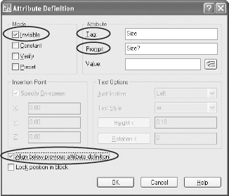
When you're defining attributes, you have the option of setting their mode to Invisible, Constant, Verify, or Preset. The modes affect attributes in the following way:
Invisible Sometimes attributes are used to create text that's part of a drawing; the values entered into a title block are a good example. Such values must be set to the Visible mode. Other times, attributes are used to store information in the drawing that's not part of the drawing itself. Using attributes for storing costs, or model numbers of parts may fit into that category. In that case, values must be set to the Invisible mode. No matter what mode is selected when attributes are first defined, they can all be made to display or not display using the ATTDISP variable.
Constant If the value of a specific attribute will never change from the default, you can use this mode. An attribute value in this mode cannot be edited with DDATTE or ATTEDIT.
Although I normally recommend against using Constant, because Preset allows you to make future changes, there's one situation where using this mode is useful. If you want a value that never changes but can still be extracted from the drawing using ATTEXT or EATTEXT, make it a constant attribute.
Verify When a block containing attributes is inserted into a drawing, the operator may be prompted for the value of the attribute, depending on the setting of ATTREQ andATTDIA. If you enable verification, the operator will be asked to verify each of the values given after they have been typed in. Although this may increase accuracy, it also takes time. I recommend against it except for values that are critical and prone to mistake, like part numbers.
Preset If the value of a specific attribute is nearly always the same, this setting can be used to automatically use the default when the block is inserted. It's still possible to edit a preset attribute value using the EATTEDIT, -ATTEDIT or ATTEDIT command.
You have several options when defining attributes. The options include:
Tag You can use any character that can be typed at the keyboard to name a tag for an attribute definition, as long as it has no spaces. Try to create tags that are short and descriptive.
Prompt You can place anything you want in the prompt window, including spaces. However, I recommend that your prompt consist of the tag name you used followed by a question mark. The Edit Attributes dialog displays the prompt but not the tag. If the prompt is always the same as the tag, you always know the tag name even when only the prompt is listed.
Value This is where you can place a default value. You can also set Attribute Mode to Preset so this value is used automatically. If you need to change it, you can use one of the editing commands.
You can also use this as a place to reinforce the format in which you want information to be placed. You may place a dummy date here, for example, so users remember what date format to use. Just make sure you change it to the correct date when you insert the block.
Insertion Point Click OK to pick a point for the location, or select Align Below Previous Attribute Definition to locate the attributes. The attribute tags show up at that location.
Note
If your attribute definition doesn't show up where you expect, it may be at the default location of 0,0,0. If so, you forgot to pick a location.
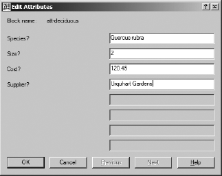
When you insert the block, the Edit Attributes dialog appears, allowing you to fill in the values you want. If it doesn't appear, you may have ATTDIA turned off, in which case you'll be prompted at the command line. If you get no dialog box and no command-line prompt, you may have ATTREQ turned off. The Edit Attributes dialog in Figure 5.13 shows the tag Species with the value Quercus rubra.
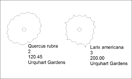
Whether the values you place are visible on the screen depends on whether you defined attributes that are invisible. Most attributes for things like species, size, and cost are invisible—you want the information, but you don't want it shown on the drawing. One exception is a title block. When you create your title block, the attributes should be visible; otherwise, you won't be able to read them in the drawing. If you want to see and/or plot invisible attributes, you can set the variable ATTDISP to ON, as in Figure 5.14.
Attribute values can be useful even if they are only used to display information in a drawing, but they are most powerful when you use them to attach information about each block reference. Most of that information will be invisible, so you have to be able to extract it from the drawing in order to use it. That process can be done in one of two ways. I'll go through both. One is easier when used manually, the other useful for extracting attribute values using an AutoLISP program.
There are two methods for extracting attribute information: EATTEXT and ATTEXT.
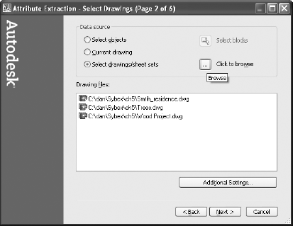
The EATTEXT command displays the Attribute Extraction Wizard. It's easy to use, and with it you can extract attribute data from a group of selected block entities, either from the current drawing or from any saved drawing or set of drawings that have been referenced into a sheet set. (See Figure 5.15.)
Once you identify where you're going to get the data, you can extract it into one of several different formats, as shown in Table 5.2
Table 5.2. Formats for Extracted Attribute Values
FORMAT | DESCRIPTION |
|---|---|
Table | A table is an AutoCAD object that contains rows and columns of cells. It wasn't until AutoCAD 2006 that attribute values could be extracted into a table, but that feature has become a favorite for this process. Tables are the only internal format for attribute extraction. |
CSV | The Comma Separated Value format is also known as the comma-delimited format. It's an ASCII text file with each field within a record separated by a comma. Because this is a common means of delimiting (separating) data, it's a good idea not to include a comma as part of the value you assign to an attribute. It's also common for values in CSV format to be differentiated by placing character values in single quotation marks while leaving numerical values unquoted. |
MDB | The Microsoft DataBase format is used by Microsoft Access for its database files. You'll see how to use Access with data from an AutoCAD drawing later in this section. |
XLS | Excel Spreadsheet format is used by Microsoft Excel for its spreadsheet files. Although there's some similarity between a database and a spreadsheet, they're very different. However, it's possible to extract attribute values from AutoCAD directly into the cells of a spreadsheet. It's also fairly easy to convert an MDB file into an XLS file and vice versa. |
TXT | This is a plain ASCII text file with one record per line and the fields within records separated by spaces. This type of file can be imported into an AutoCAD drawing, but it's hard to line up the columns using an acceptable font. All but a couple of AutoCAD's font options are proportionally spaced, so any time you try to use a TXT file with columns of data, you get wavy columns. |
The other method for extracting attributes, the ATTEXT command or its command-line equivalent, predates the EATTEXT wizard and is much more involved. I still consider it useful, though, because it can be used with a script or an AutoLISP program to automate the extraction of attributes from multiple drawings. (See Chapter 8.) ATTEXT involves a number of steps.
Before extracting attribute information from a drawing, you have to create a template file to tell the software how the information should be extracted. This template file must be an ASCII file. It can be created in any word processor, but because you must save the file in ASCII format, I recommend using Notepad. EDIT is a DOS alternative that's run from the system command prompt, but its only advantage over Notepad used to be its line counter. (EDIT was the replacement for the dreadful EDLIN text editor. If you remember using that, you can definitely claim the title of "computer old-timer.") If you're using the XP version of NOTEPAD, the View pull-down menu gives you the option of viewing a line counter. There are also other text editors that you can find as shareware or buy. You can even use VLISP, if you find it helpful.
Don't leave any blank spaces or blank lines in this template file. When you try to extract attribute values, if you get the error message "invalid field specification" when you extract the data, you may have a blank line at the end of the file. Remove any extra lines by moving your cursor to the end of the file and using the Backspace key to delete them. Don't use the cursor keys, because the blank lines will still be there. The cursor should end up at the beginning of the blank line that immediately follows your text. Before saving the template file, use the Down Arrow to move your cursor to the end of the file. If the cursor doesn't stop directly below the last line, remove the blank lines, and check each line to make sure you have no spaces at the end of any individual line.
In the template file shown, the first two lines represent attributes that all block references have; they aren't tags that you can create. All blocks have a block name, layer name, a linetype, the coordinates of its insertion point, and other information. If a block includes at least one custom attribute, you can also extract the general attributes. If you use the EATTEXT wizard, you can extract general data from any block, regardless of whether it has any user-defined tags.
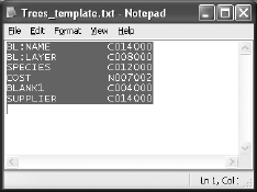
The BLANK1 tag creates a space between a right-justified numerical field and a left-justified character field, not because it's named BLANK, but because no values are assigned to that tag. Any false tag name can be used to create spaces, but only once. This file must have a .txt extension and be an ASCII text file. The file appears as shown in Figure 5.16 if you highlight the entire file to make sure it has no blank lines.
An explanation of the file is shown in Table 5.3.
This template file list provides six rows of information in an extracted file: the block name, layer, species, size, cost, and supplier. The second column in the template file specifies the kind of data (characters or numbers), the field width (008 = 8 characters), and numerical precision (002 = 2 decimal places). All character-based fields have a precision of 000.
Once you've created a template file, open the drawing that contains attributes and use ATTEXT or EATTEXT to extract them. You can specify a filename for the extracted data, or let AutoCAD use the drawing name. In this case the result of extracting block information from two tree symbols using this template file is another text file like the following.
Table 5.3. Trees_template.txt
TAGS | FORMAT | EXPLANATION |
|---|---|---|
BL:NAME | C014000 | BL: means BLOCK. This extracts the block name. |
BL:LAYER | C008000 | This extracts the layer on which the block resides. |
SPECIES | C012000 | This is a Character field, because it includes letters. |
SIZE | C008000 | This is a Character field in case ft is used in an attribute. |
COST | N007002 | This is a Numerical field. It's right justified so no $ characters appear in attributes. |
BLANK1 | C004000 | This is a space between fields—any nontag word is OK. |
SUPPLIER | C014000 | This is a Character field because it includes letters. |
What appears in bold is part of the text file created by AutoCAD. The first example is comma delimited:
'att-deciduous','trees','Quercus rubra','2', 120.45,'','Urquhart Gardens''att-conifer','trees','Larix americana','3', 200.00,'',' Urquhart Gardens '
The second example is space delimited:
att-deciduous trees Quercus rubra 2 120.45 Urquhart Gardensatt-conifer trees Larix americana 3 200.00 Urquhart Gardens
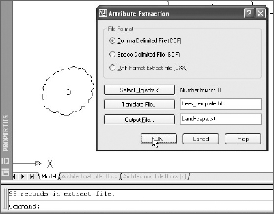
Once the information is extracted into a text file, you can insert it into the drawing as text or import it into a database program like Microsoft Access so you can organize the information in any way that's useful. When you use the ATTEXT command, you must decide how the information identified in the template will be listed in the extraction file. The choices are comma delimited (CDF), space delimited (SDF), and Drawing Exchange Format (DXX). DXX is a partial DXF file, containing only block and attribute information. The .dxx extension is used to differentiate the file from a standard DXF file. It has no value to most users. Use SDF for information you want to be able to read or import into AutoCAD. Use CDF if you plan to use the data in a database application. See Figure 5.17.
An XRef is a drawing that's externally referenced. The process of attaching an XRef is similar to using the INSERT command to bring another drawing into a host drawing, but the result is much more powerful. XRefs allow you to use a single drawing file as a reference in multiple drawings so that the most current version of the XRef is always displayed.
XRefs also let you make a single master drawing from many smaller drawings, even if different designers are working on each of the smaller drawings. XRefs must be managed carefully. They work best in a network environment with clear standards on filenames, locations, and base points for the geometry created in the drawing. In other words, they work best in an office with a good CAD manager.
When you attach an existing drawing file to a host drawing, the external reference doesn't become a part of the new drawing unless you decide to bind it. Instead, AutoCAD stores the location and name of the referenced drawing in the host drawing.
Whenever the new drawing is opened, AutoCAD locates the XRef and displays it. If the XRef has been changed since the last time the new drawing was edited, the changes are automatically reflected in the new drawing. XRefs can also be nested, just like blocks.
Using external references permits several different designers to work on components or subassemblies of a large drawing project. A master drawing of an entire assembly may consist of several XRefs, one for each subassembly. Whenever the master drawing is loaded into AutoCAD, the latest version of each subassembly is loaded as well. When all revisions are complete, XRefs can be bound to the master drawing and become a single drawing file. In most cases, XRefs are maintained and the individual drawings are never bound to the drawing.
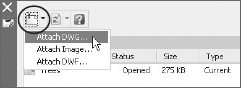
To attach an XRef, issue the XREF command. If you use an release earlier than AutoCAD 2007, you get the External Reference dialog. In AutoCAD 2007, you get a palette that combines the XREF, IMAGE, and DWFIN commands and that lets you manage all three kinds of externally referenced files. All the functions of the pre–AutoCAD 2007 dialog box are available through the palette—you just may have to right-click a filename to find them.
Let's start by attaching an XRef. Pre–AutoCAD 2007 brings up a dialog box that contains an Attach DWG button. Click it to attach a drawing, image, or DWF file. In AutoCAD 2007, click the Attach icon as shown in Figure 5.18. In both pre-AutoCAD 2007 and AutoCAD 2007, you get the same dialog box (see Figure 5.19) in which to select and control the external reference.
Once you select the drawing you want to reference, the External Reference dialog box shown in Figure 5.19 is displayed. The bottom portion gives you the same options that the INSERT command gives for inserting blocks. The top portion, however, gives you several choices specific to external references.
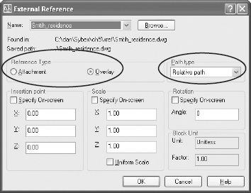
You have an important choice to make for Reference Type: Attachment or Overlay. If you select Attachment, your XRef will be visible in the current drawing and in any drawings to which the current drawing is attached as an XRef. If the current host drawing is attached to another drawing, any attachment-type XRefs will become nested XRefs and will always be displayed. That may not be desirable if the nesting gets deep enough that the detail in this drawing won't be readable.
If you select Overlay, the drawing you're referencing will be visible only in the current drawing. If the current drawing becomes an XRef in another drawing, overlay XRefs contains won't display.
You also have the option of selecting Full Path, Relative Path, or No Path. If Full Path is selected, the absolute path, including the drive letter and each folder in the path, is used to locate the drawing when it's needed. If it's not found in the full path, AutoCAD looks in the current folder. If AutoCAD doesn't find the XRef in the current folder, it looks in the default path locations. If it can't find the drawing, a text string identifying the XRef is displayed at its insertion point instead.
If you select the No Path option, no path is saved, and the XRef is found only if it's in the same folder as the host drawing. That's not a bad idea, especially when you're transmitting drawings and their XRefs to another user. However, it gets cumbersome with large projects that have multiple XRefs.
The Relative Path option was added in AutoCAD 2005. It's useful when you need to copy an entire folder structure and transmit it to someone else, where it may be placed on a drive with a different drive letter. This method stores the path of the XRef relative to the location of the host drawing file into which it's inserted. There are two requirements for using the Relative Path option: You have to save the host drawing before attaching an external reference file, and the XRef must reside on the same drive as the host drawing.
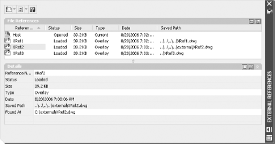
The conventions for displaying a relative folder path are shown in Table 5.4.
When there are more folder levels, another .. is added for each. For example, if a host drawing named HOST.DWG is saved in the folder C:dandadwg and has four XRefs, their relative paths are displayed as in Table 5.5.
The AutoCAD 2007 External References palette displays these XRefs as shown in Figure 5.20.
Table 5.4. Relative Path Designations
PATH DESIGNATION | EXPLANATION |
|---|---|
| From the folder of the host drawing, follow the specified path. |
| From the folder of the host drawing, move up one folder level and follow the specified path. |
| From the folder of the host drawing, move up two folder levels and follow the specified path. |
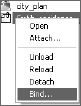
Once you've loaded your external references, you manage them using the same palette (in AutoCAD 2007) or dialog box. You can detach them, reload them to get the most current version, unload them, change their path, change their type, or bind them to the drawing permanently.
The Bind option gives you two choices: Bind or Insert. This is also an important decision. Binding an XRef turns it into a block, as though you had used the INSERT command instead of attaching the drawing as an XRef. The choice between Bind and Insert determines how the names for layers, blocks, dimstyles, and so on are treated. Let's look at how those names are treated in XRefs before they're bound.
When an XRef is attached to a drawing, AutoCAD differentiates the layers, blocks, and dimension styles in the XRef from those in the host drawing. To distinguish XRef elements from the host-drawing elements, their names include the XRef drawing name as a prefix. A layer with the name Cen in an externally referenced drawing named Smith_residence.dwg is displayed in the host drawing as Smith_residence|Cen.
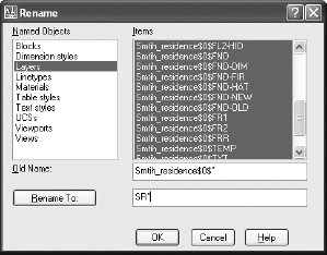
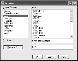
Use the Bind option. Otherwise, you may find that your text styles, dimension styles, and block definitions that use the same name as their counterparts in the host drawing have been redefined. Once you use the Bind-type option of Bind, you'll have some fairly long and cumbersome names for layers, block definitions, text style, and so on. You can quickly rename them by using the RENAME command and applying a wildcard (*) to select all the XRef names. For example, if the names of these elements are prefixed with Smith_residence$0$, you can type Smith_residence$0$* for the old name and a new prefix followed by the wildcard—SR*, for example. Figure 5.21 shows the original bind names, and Figure 5.22 shows the result of using the wildcard to rename them.
Note
Layer 0 and the Defpoints layer behave differently in XRefs than other layers do. They are not identified separately with their drawing name as a prefix. When bound to a host drawing, all entities on the 0 and Defpoints layer in each XRef will be placed on the same layer. For this reason you should avoid placing any entities on either the 0 or Defpoints layer if you intend to use the drawing as an XRef.
When you first attach an XRef, the layer visibility of the XRef is determined by its visibility at the time the XRef was last saved. However, you can alter the visibility of XRef layers from within the host drawing to control the display of the referenced drawing. VISRETAIN controls layer visibility the next time you open the host drawing. Will the host drawing display the layers as they appeared when the XRef was saved or when the host drawing was saved?
If VISRETAIN is set to 0, changes to layer visibility in the host drawing are temporary, and XRef layer visibility reverts to the XRef drawing when the host drawing is reopened. If VISRETAIN is set to 1 (the default), layer settings are saved with the host drawing and persist from session to session. Normally, you should leave this setting at 1.
When a large XRef is brought into a host drawing, it often contains far more geometry than the drawing requires. To prevent unwanted geometry from being displayed, you can use the XCLIP command to clip an external reference into either a rectangle or a polygon. If you want the frame of the clipped area to show, set the XCLIPFRAME system variable to 1; if you don't want it to show, set this variable to 0.
Note
XCLIP also clips block references.
When a drawing contains many external references or a very large external reference, performance during editing slows down. To reduce the amount of computer resources necessary to manage the host drawing, two indexes can be saved with a host drawing and used during demand loading of external references. These indexes keep track of which XRef-dependent layers are currently thawed and how much of an XRef is being displayed as a result of the XCLIP command. These indexes are added to the database of the host drawing, making it slightly larger, but the performance gain in not loading all layers and all geometry (spatial indexing controls the appearance of geometry) generally makes up for that slightly larger file size.
The INDEXCTL variable controls whether indexes are saved with a host drawing. Its settings are shown in Table 5.6.
Table 5.6. INDEXCTL Settings
INDEXCTL SETTING | DESCRIPTION |
|---|---|
0 | No indexes are created. The entire external reference loads with the host drawing. |
1 | A layer index is created. Only thawed layers load with the host drawing. |
2 | A spatial index is created. Only geometry displayed within an XCLIP is loaded with the host drawing. |
3 | Layer and spatial indexes are created. Thawed layers and XCLIP geometry are loaded. |
You don't need to remember this variable when working with host drawings. All this can be controlled in the SAVEAS dialog box by selecting Tools and then Options. The resulting dialog box allows you to select an index option.
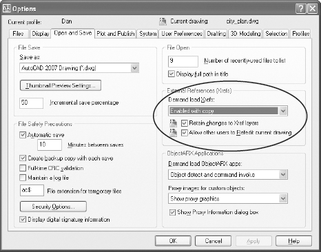
Once you've created and saved an index with your host drawing, you have to enable demand-loading before you gain any performance from setting INDEXCTL. To enable demand loading, either use the variable XLOADCTL or use the Open And Save tab of the Options dialog box, shown in Figure 5.23. Demand Load Xrefs → Enabled With Copy is generally the fastest method when you're working on a network. Only the layers and area specified by INDEXCTL are loaded when a drawing is opened that contains XRefs and the referenced drawings aren't locked.
Although it can be used to edit blocks, the intended application of the REFEDIT command is to edit external references from within a host drawing. This is a potentially very dangerous command, because any changes you make while using it can be saved to the original external reference. Because double-clicking an XRef opens the block editor, it's possible to edit an XRef without noticing it. If you want to prevent the use of REFEDIT on a particular external reference, open that reference drawing and set XEDIT to 0 before saving it. Now you'll have to open the drawing before making changes—a safer method for editing reference drawings, in my opinion.
Fields and tables work together to add significant functionality. They first showed up in AutoCAD 2005 and represented two of the most significant additions to that release. Fields pretty much replaced the Express Tool RTEXT for me, making it much easier to add automatically updated information to drawings—mostly because you don't have to understand diesel expressions to use Fields. Tables finally made it possible to do something that had always been clunky in AutoCAD—organize text-based entities as part of a drawing.
Fields are potentially useful and powerful tools. They can be variable, in the sense that values in fields can be made to change automatically. A date field, for example, always contains the current date (although a REGEN may be necessary to match the display to the value). A system-variable field always contains the current setting of that variable. You can customize fields using the following drawing properties and diesel expressions:
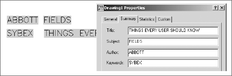
You can create drawing properties (title, author, comments, keywords, or custom) from the File pull-down menu. Once you've defined custom properties, they're listed by the names you gave them in the list of possible fields. Change the properties, and they change in the field location (either in a table or anywhere else). (See Figure 5.24.)
Diesel expressions can also be used in fields. However, spreadsheet-like equations were added to tables in AutoCAD 2006, and so many existing fields are specified that it's unlikely you'll need to use diesel. But, who knows what you may find to do with it?
Many of the fields are obvious: date of creation, which doesn't change; date, which does change; time; and so on; but some are more subtle. The listed fields when you right-click in MTEXT and select Insert Field include the following, plus any custom-drawing properties you create. The asterisk is used here as a wildcard. Wherever it appears, the category has multiple fields that are related.
Author (DWG property) | LastSavedBy |
BlockPlaceholder | LispVariable |
Comments (DWG property) | Login |
CreateDate | NamedObject |
CurrentSheet* | Object |
Date | PageSetupName |
DeviceName | PaperSize |
Diesel Expression | Plot* |
Filename | SaveDate |
Filesize | Sheet* |
Formula | Subject(DWG property) |
Hyperlink* | SystemVariable |
Keywords (DWG property) | Title (DWG property) |
Note
Don't overlook the SystemVariable field, which gives you access to 400 or so variables. The Filename field gives both the default path and name of the current drawing. For just the filename without the path, place the variable DWGNAME as a SystemVariable field. For a list of all system variables, type SETVAR
Creating tables was never easy in AutoCAD, although you've been able to import Access and Excel files as OLE objects since Release 14. Finally it's possible to create and edit tables that retain their format and contain actual data—either text data or fields. Fields are the most interesting of the data types—particularly in AutoCAD 2006, which allows equations to be entered into cells in the table. And if you decide to use a table in some other application, it can be easily exported to a comma-delimited text file that can be read by database and spreadsheet software.
Before I get into specifics about using the calculation functions of tables, here are a few general recommendations:
Create a table style (click the ellipses button in the Insert Table dialog box) that uses a proper font, with text heights that meet standards, and give it a name other than Standard.
To enter a field into a table cell, double-click in the cell to open the MTEXT editor. Now, right-click to bring up the MTEXT menu, and select Insert Field.
To edit a table (column sizes, and so on), select the table, right-click to bring up the context-sensitive menu for tables, and select Properties. Now you can use the Properties palette to change the table's structure.
Each cell in a table has a designation that consists of both a letter and a number.
AutoCAD 2006 gave tables a big boost by adding the ability to place formulas in individual cells that can reference other cells, just like in a spreadsheet. The columns in a table are identified alphabetically, the rows numerically. However, the letters and numbers used to identify each cell aren't displayed. You have to know how the table is structured to figure out how any given cell is named. It's a bit of a mystery but easily solved. Every row, even one that consists of merged cells, must be counted. The same is true for columns. If you have used an application like Microsoft Excel, this format will be familiar.
Note
AutoCAD always includes sample files that demonstrate various features, particularly when those features are new. The drawing used for Figure 5.25 is one example. For a default installation, the sample files are found in C:Program FilesAutoCAD 2007Sample. This folder contains some great stuff that can help you understand how some of these features work. You may find that the sample files weren't installed. If so, it's worth adding them using the installation wizard on the original CDs.
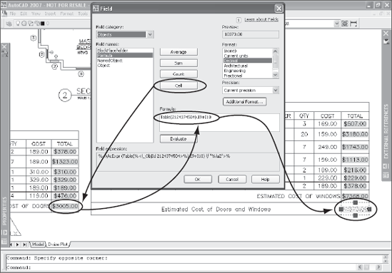
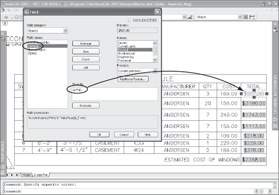
Figure 5.25 shows a table entity. It appears in Blocks and Tables - Imperial.dwg, one of the sample drawings that ship with AutoCAD 2007, so you can open it and see how tables and fields can be used. Each of the highlighted text blocks in the last column (Column I) is a field. In each of these cases, they're fields representing formulas. If you select and right-click one and open it for editing, the Field dialog box opens, as shown.
The formula for cell I3 is shown in the window of the dialog box as G3*H3. This multiplies the value in cell G3 (3) times the value in cell H3 (169.00), for a total cost. The total cost (507.00) is displayed as a field. You can tell it's a field because it's highlighted in the AutoCAD display but the highlighting won't plot.
Note
Fields don't have to be highlighted. You can turn off field highlighting by setting the system variable FIELDDISPLAY to 0 instead of the default value of 1.
You can apply any of the standard math functions (tan, sin, sqrt) from the CAL command to any cell by using a formula like sin(H3). You can also group expressions that include division, multiplication, subtraction, and addition in the same way you can with a spreadsheet: (g3*h3)/2+(h5*h7)/3, for example.
The last cell, I10, contains the formula Sum(i3:i9), which adds all the values starting with cell I3 and going through cell I9. If you look at the dialog box again, you'll see buttons for Average, Sum, Count, and Cell. These formulas can be applied across multiple cells within a single table or applied to individual cells in other tables:
Cell In case you missed the significance of the italics, let me emphasize something: You can place the value of a cell into one table from a different table. To do that, you click the Cell button shown in Figure 5.26 and then select an individual cell in any existing table. That's pretty nifty. The resulting formula has the following format:
Table(2124374504).I9+I10. The value (2124374504) is an internally assigned name for the individual table. It isn't assigned by the user.Average This button prompts you to select a range of contiguous cells, whose values are then added together and divided by the number of cells selected. The formula looks like this:
Average(G2:G9).Sum This button prompts you to select a range of contiguous cells, whose values are then added together. The result is a formula that looks like this:
Sum(H3:H9).Count This button prompts you to select a range of contiguous cells, and the total number of cells selected is shown. The formula looks like this:
Count(G3:G9).