
Considering the complexity of AutoCAD, it's not surprising that many people who use it miss something important along the way. Many users had little training on the software before being expected to start producing useful work, and these users in turn have trained others based on what they figured out on their own. Even the most experienced AutoCAD users have likely forgotten some useful things they once knew.
This chapter is the result of the many questions I've been asked by AutoCAD users over the years while teaching, training, consulting, and responding to e-mails and phone calls. Here I'll offer advice on using AutoCAD, with an emphasis on features and techniques that are often overlooked or forgotten by users. I'll include general design advice that applies to the use of any CAD system, providing my recommendations for universal standard practice in using AutoCAD, reviewing techniques and commands that apply to all releases of AutoCAD.
This chapter isn't meant to be a comprehensive review of AutoCAD—many excellent books already provide that—nor is it a replacement for learning how to use the software. What I've selected here are items that people often overlook.
Design Standards
AutoCAD Best Practices
Feature Review (All Releases)
CAD software is used in so many fields of design that it would be impossible to develop extensive standards that apply to all of them. I've trained people who use AutoCAD to design quilts, hearing aids, doll clothes, houses, barns, commercial buildings, M16s, submarine hatches, and the myriad components of machinery. But there are some foundational rules that represent a consensus among serious users of CAD. You'll find exceptions to these rules, of course, but think of them the way you think of the rules for dimensioning drawings: You follow them if possible. The fact that a rule has rare exceptions doesn't reduce its value as a guide. You certainly follow the rules requiring you to drive on the proper side of the road all the time—except when a dog darts out in front of you, or the road is washed away by a flash flood, or you're passing someone. So, here are some of my rules for using AutoCAD.
Unless you have a very good reason not to, draw everything at its actual size. Even details can be drawn full size, if you use layouts. They may not look right to you in the Model Space tab, but you can display them in Paper Space viewports and give them any scale you want. At one time, you would have used the SCALE command and then set DIMLFAC to compensate for dimensions, but that's not a good idea now. You know why. At some point, you'll forget that your dimension style is multiplying every dimension by 2; or you'll dimension a detail and forget to change DIMLFAC, and all the dimensions will be half their actual size. You have a complex enough job as it is, keeping track of so many details. Why not simplify your life by drawing everything the size it's supposed to be? You're not at a drafting table. Worry about how something will plot when you set up a layout.
I've done a lot of training for different industries and have looked for situations where it was impossible to draw full size; I haven't found an instance yet that couldn't be addressed using Paper Space. At one shop I worked for, two groups of designers who used AutoCAD had a difference of opinion about full size versus scale. One group of designers thought they couldn't draw full size because they were designing long pieces with almost no detail along their lengths but a lot of detail at the ends. They only drew the ends, and then they broke the piece with a conventional break and plotted it for the fabricators. The dissenting designers wanted to draw parts at their actual lengths so they could use them in assembly drawings without re-creating them.
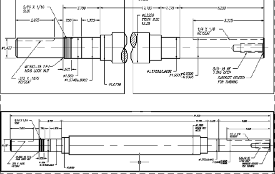
The solution I offered was to draw the pieces full length, with proper end detail, and then create a layout with two viewports to represent each end of the object. As long as the two viewports were at the same scale and aligned, they could be separated for a break symbol to be added in Paper Space. Even the dimension of the overall length was correct, because it was in Model Space (where I think it normally belongs). They could drag the value right or left so it could be seen in one of the viewports. (See Figure 1.1.) The entire part is shown at the bottom, with the conventional break created with two floating viewports above.
This tip probably seems obvious, but I've been asked more than once what I recommend when designing for renovations or additions to existing structures. The question is usually in this form: "I have the original drawings of the building. Should I use them to create an AutoCAD drawing of the existing structure, or should I create the AutoCAD geometry 'as-built'?"
Clearly, creating geometry "as built" rather than "as designed" permits you to solve problems in the software instead of in the field, because few actual structures didn't change in some way from the original plans. You can use the original plans to create a base drawing and then check key locations and dimensions for changes. This is one of the great benefits of using such a precise design system. You can reduce what some builders call on-site engineering by drawing everything as accurately as you possibly can. That way, the results are much more likely to match the plans. Who knows: Someday "as built" and "as designed" may become the same thing.
My advice to draw mechanical parts at Maximum Material Condition (MMC) may be less obvious than my "as-built" advice, because mechanical parts always have a specified tolerance—at least, they're supposed to. The question is, where in that range should you create your accurate-to-15-decimal-places geometry when using a CAD system? (You know it's impossible to make anything an exact size. If you think you can, you're not using a precise enough measuring tool.)
There are several possibilities. Some people draw objects in the middle of their size tolerance range. Others use what they consider the design size or nominal size—the base size given before the plus/minus sign. After all, isn't that the ideal size? Well, it may be the ideal size, but neither of these approaches is good practice, whether you're creating a 2D drawing or a 3D model. The fact is, a mechanical part has no ideal size. If a part is designed properly and given a functional tolerance, as required, it will work fine as long as its dimensions fall within that tolerance. No size in that tolerance will make the part perform better than any other size. As a machinist, you may aim for the middle of a range, but not because that makes a better part. You do that to reduce the chances of making the part too small or too large and having to throw it out.
Draw all parts and create all solid models at MMC unless it's one of those rare features that are controlled at Least Material Condition (LMC) in a tolerance frame. Features with outside dimensions, like a shaft or a pin, should be drawn at their largest acceptable size. Features that have inside dimensions, like a hole or a slot, should be drawn at their smallest possible size. In both cases, the result is a part with the maximum amount of material in it. That's usually when parts are least likely to go together; this approach allows you to draw parts in the situation where they're most likely to fail and to check for interferences more readily. It's also easier to be consistent this way, because the rules for Geometric Dimensioning and Tolerancing assume MMC for many of the specific situations where the rules apply. I recommend this approach for both 2D and 3D modeling, including when you're using Mechanical Desktop, Inventor, or any other CAD package.
When designing something, you can use any size increment you wish. If you choose increments that are easy to work with, or that result in less waste during fabrication, you save both time and materials. During the early design stages, you can set a SNAP to that increment in AutoCAD, with a GRID set to twice the increment. Doing so can speed up the initial layout.
For architectural design, I recommend using the largest increment possible, such as whole inches, one foot, two feet, or four feet. Doing so makes it much easier to use standard-sized sheets of material during construction. For mechanical parts, use increments of 2mm or 0.1 inches if possible.
I've been training people to use AutoCAD for technical graphics and design since the late 1980s. At that time, I frequently got resistance from drafters and designers who felt I placed too much emphasis on absolute accuracy. They would point out that once a drawing is plotted, the absurd 15 decimal places of precision that AutoCAD uses for calculations become meaningless. Once you plot a drawing, even significant errors are difficult to detect, as long as you carefully replace any key dimensions with those you typed in.
I believe all industries that rely on computers for design and documentation should share common standards when using CAD software. In this section, I offer advice on accuracy and other aspects of AutoCAD that should be standard practice across all disciplines. If you understand AutoCAD, it's faster to produce an accurate drawing than an inaccurate drawing. You or your company have probably invested upwards of $7,000 to put you in an AutoCAD seat, so why not produce as accurate and useful a drawing file as possible?
The AutoCAD Help system has become one of the best Help systems available in any software. If I had to identify one AutoCAD feature as the single most underused, this is it. I've gotten many phone calls from people who have an AutoCAD question that I answer by simply going to the AutoCAD Help system. Use it. It keeps getting better and better. It's a model for what a Help system should be.
Blocks can dramatically reduce file size, allow you to quickly update large amounts of work, and make your drawings more consistent. Any time you create a symbol, standard detail, title block, or other collection of objects that you may ever want to use again, consider creating a block definition.
Once you've used a block, don't explode it unless you have a good reason. This is especially true for dimensions. Once you explode it, the block entity no longer exists. You lose the ability to update the dimensions, and you increase the file size (sometimes dramatically). Dimensions will no longer update values when you modify geometry, and you can't update dimension appearance with changes to dimstyles. Don't explode hatch patterns, either, for the same reason.
When you're adding dimensions to drawings, it's tempting to type in the correct value when a dimension is wrong. Unless you absolutely don't have the time to do it, redraw the geometry so it's correct, and then add an associative dimension. Otherwise, you and everyone who ever uses your drawing will assume it's correct—with potentially dire results.
If you do override a dimension because you just can't help it, then make sure you flag the change, or note it so you can go back and re-create the geometry later when you have time.
Note
When I'm dimensioning architectural plans, I set precision to an increment of 1/256 in the Primary Units tab of the Dimension Style dialog box. That's ridiculously small for a dimension, but by using such a small increment of precision, I know immediately if there's an error in the geometry as I'm adding dimensions. If there are no errors, the proper dimension value is displayed. If you set the increment to a whole number, for example, small errors are masked by being rounded to the nearest inch.
Using layers with logical names allows you to separate different kinds of geometry and different functions. Don't be one of those people who produce nightmare drawings by placing all or most entities on a single layer. Layers give you control over a drawing that's essential to efficient management. If your layer names are logical, it's easy to manage multiple layers.
That logic should be embedded in an office standard and reflected in the use of standard drawing templates, and a .DWS standards file. There have been many attempts to standardize layer naming across disciplines. See Chapter 4, "Applying Graphics Standards," for more information.
Unless you have a good reason, avoid the urge to use multiple colors, linetypes, or lineweights on a single layer. If you get a drawing from someone who has done this, use FILTER or QSELECT to select and move objects to different layers, and then change their properties to ByLayer.
Good reasons may include the desire to create a symbol or detail that contains multiple linetypes and colors. Although this can be done by using objects on different layers, many users prefer to have all elements of a block definition reside on a single layer so only that layer controls the appearance of the block. In this case, you can apply a specific color or linetype to an element before including it in a block definition.
Note
If you find it necessary to apply a color or linetype directly to an object rather than to ByLayer, I recommend doing so with the Properties palette after the object is created. If you select the color in the Properties toolbar, you may forget to set it back to ByLayer and continue drawing. You should close the Properties toolbar to avoid using it. See Figure 1.2.
Learn to use direct-distance entry, osnaps, object tracking, temporary tracking, and polar tracking. They're great tools that can dramatically speed up your work once you understand how they work together. Check out the newer osnaps, like M2P, Temporary Track Point, Parallel, and Extension. However, don't overdo the running osnaps. Open the Drafting Settings dialog box, and uncheck as many as possible in the Object Snap tab.
Note
If you're drawing lines at unusual angles, and you want to be able to continue with lines that are perpendicular from the last line segment you drew, set PER as a running osnap and hover over the end you just selected.
Read Chapter 6, "Plotting," for the full story; but for now, follow these steps in sequence when you create a new drawing file:
Create your geometry full size in Model Space, but don't add dimensions, text, or hatches.
Set up a layout with all views at the proper plot scale.
Add dimensions, text, hatches, and schematic symbols to your drawing from a layout with a properly scaled viewport.
Note
Use the command CHSPACE (an Express Tool before AutoCAD 2007) to move objects between Paper Space and Model Space. If you put something in the wrong spot, it's easy to change it and have it scaled automatically so it plots as you intend.
I've heard some horror stories about AutoCAD drawings that were done using the Etch-A-Sketch® method and then reused later by someone who assumed they were done accurately. Most of these stories involve hapless users stuck with their predecessors' drawings, but in some cases users run into trouble by relying on their own inaccurate drawings. In one case, which involved a lawsuit and a lot of money, a bid was made on a structural design based on the assurance that accurate AutoCAD drawings of the existing structure would be provided by the client. Unfortunately, those drawings were facilities drawings—done to show egress and general locations—and were unusable for the intended purpose.
How does this happen? Because most AutoCAD drawings look accurate even if they aren't, we forget that we created something quickly by sketching and then saved the file.
Note
It's quicker to use the accuracy tools built into AutoCAD than to draw by eye, so why not use them?
If you set the height to a fixed value when creating a new text style, the text can be used only at that height no matter how you set the text height in your dimstyle. Setting a height of 0 gives you control over text height every time you enter the height. If you can't read a dimension because the text is too small, but you can see the arrowheads, you've specified a fixed height in your text style.
The name Standard is used as a default name for the text style, dimension style, table style, and probably a few other things in AutoCAD. It's misleading, because it's a standard only in the sense that it always shows up in an AutoCAD environment. Never does the name represent a real standard in any discipline. To avoid a nasty surprise down the road, build a template file that banishes Standard as a name for anything.
I suggest naming text styles for the fonts they use. If you set their height to 0, you won't need all those Romans48 type names; Romans will work fine. For dimensions, give the styles names that represent their disciplines, or the name of the client. For tables, use names that represent their use. Or, use the names of your favorite pets—just don't call anything Standard.
REFEDIT is used to edit block definitions or external reference drawings; it replaces the originals if you tell it to. If you click Save Reference Edits, you'd better mean it. You can protect a drawing that will be used as an external reference (XRef) from being edited with REFEDIT by setting the variable XEDIT to 0 before saving the intended XRef. Before AutoCAD 2006, double-clicking a BLOCK insertion opened REFEDIT. Users who didn't understand what REFEDIT was would close the resulting toolbar and keep working. Unfortunately, they were still reference-editing without knowing it, and eventually they got the not in the working set error. If you get this error, type REFCLOSE at the command line.
Don't change filenames or locations for hyperlinks, XRefs, XRef images, menu files, icon BMP files, or other support files unless you know how to redefine the path used to locate them. Otherwise, you'll get blank rectangles for images and a line of text for XRefs, your menus won't load, many commands won't work, or you'll see clouds or questions marks on your custom toolbars. Using the Relative Path option can help for images and XRefs.
Starting from scratch with either an imperial (acad.dwt) or metric (acadiso.dwt) template controls the files used for linetypes and hatch patterns. ACAD.lin and ACAD.pat are used for imperial, and ACADISO.lin and ACADISO.pat are used for metric. You can change this using the MEASUREMENT variable. The imperial setting is 0; the metric setting is 1.
Changing this doesn't change the limits or the default dimstyle after the fact. When you're plotting a metric drawing, change the drawing area to Metric in the Plot dialog box if you are using a release prior to AutoCAD 2005. AutoCAD 2005 made a change in the plotting process: When you plot a drawing starting with the metric template (or when you've changed the setting for Measurement to 1), and you select a paper size measured in inches, the plot scale is automatically set to 1:25.4. If you get odd results when plotting, check this value.
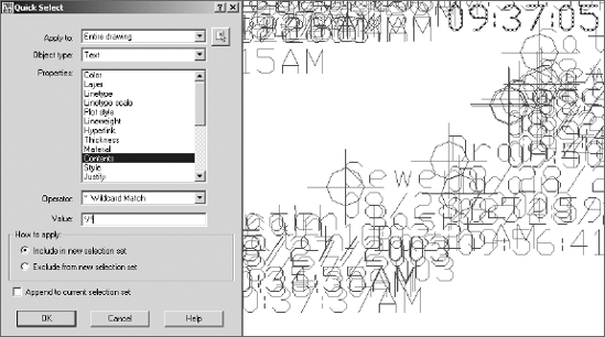
QSELECT is very useful when you're trying to fix a problem drawing. I once received a DXF file from the engineer of our city hall. He had generated a large number of points using GPS equipment to map the location of sewers, drains, manhole covers, and so on. The problem he had was that all the points and all the text were placed on one layer. The text height was so large that the text overlapped and was unreadable. See Figure 1.3.
To fix the problem, I did the following:
I used QSELECT to select all the points and put them on their own layer, which I immediately locked to protect the valuable locations generated by the GPS software.
I used QSELECT to select all the text (height 294) and change its height to 5 so it would be manageable.
I used QSELECT to select all text containing a front slash (all the dates) and put them on their own layer. This required using the * wildcard match operator (nice to know some DOS). By placing */* in the Value window, you get all text containing a front slash anywhere in the string.
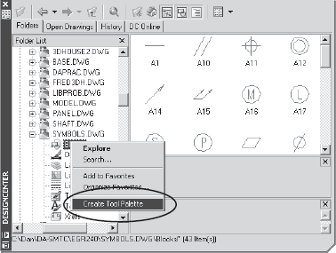
Using AutoCAD DesignCenter (ADC), you can create a tool palette that contains all the blocks from a symbol-library drawing with a single selection. Locate the drawing in the browser window of ADC, right-click it, and select Create Tool Palette, as shown in Figure 1.4.
Once you've created a tool palette, you can use it to enforce standards by setting the properties of any object on the palette, including the layer it's on (all tools), the scale (blocks and hatch patterns), and rotation angle (blocks and hatch patterns). To add a hatch pattern, use ADC to locate the file ACAD.pat or ACADISO.pat, and drag and drop a pattern to the palette.
One of the difficulties with an application as complex as AutoCAD is that everything seems to change with each release. It can get a little discouraging. Why learn the nuances of anything, when that knowledge may be worthless in 12 months? And if you do dig into a release and learn to use it productively, can you keep doing those things after the next release?
The fact is, many things about AutoCAD haven't changed over the years, including fundamentals like the underlying Cartesian coordinate system, the basic command structure, the way menus and toolbars work, the methods for creating and modifying most objects, and how files are saved. This section reviews the functionality that has been fairly constant in AutoCAD across many releases and is likely to stay that way. No matter how much things change, you'll still be able to save a specific screen display using the VIEW command; in fact, that command gets more and more useful with the development of sheet sets. There can be a big difference in drawing efficiency between one user and another that has nothing to do with new features.
Earlier in this chapter, I discussed some rules and standards for using a CAD system. Here I'll point out general AutoCAD features, big and small, that a lot of users have missed. They aren't secrets; they just seem that way if you don't know about them. And because they aren't new features, they don't show up in the New Features Workshop as spiffy and new. I think of these elements as spiffy and old. I don't care what release of AutoCAD you use, there's something here for you.
At the heart of a CAD system is the ability to create accurate geometry. Speed is always secondary to accuracy, but it's possible for one user to be much more efficient than another in creating geometry while still maintaining accuracy. That efficiency isn't merely the result of being fast with a mouse and keyboard—it's the result of planning strategies for approaching each new object to be drawn. And, of course, you must be able to get information from the drawing to check the accuracy.
The following suggestions may improve your speed and accuracy in drawing and improve your ability to get information from a drawing quickly.
COMMAND-LINE VERSIONS OF COMMANDS
One technique for becoming more efficient with AutoCAD is to type aliases and commands at the keyboard. If you can't type, you may be out of luck; but when I watch keyboard jockeys use AutoCAD, I see countless places where they save a few seconds here, a couple of seconds there, and pretty soon it adds up to real time. But what happens if the command brings up a dialog box? You have to wait for the dialog to display, grab your mouse, make some picks, click OK, and get back to work.
It may be faster if you don't have to deal with a dialog box, and many AutoCAD commands have both a dialog-based version and a command-line version. When they do, you can issue the command-line version by placing a minus sign in front of the command name or its alias: for example, -AR or -ARRAY. This behavior is in AutoCAD to protect legacy applications written by users of past releases, but you may find it more efficient than toolbars, tool palettes, or pull-down menus.
Knowing how to bring up a command-line version of a command is a godsend when you write AutoLISP programs. You can check the sequence for creating layers, for example, by typing -LA or -LAYER to avoid the dialog box and see the prompts.
Speaking of the LAYER command, let me use it as one example of efficiency. When I need a new layer—say, one named newlayer—for something I'm about to draw, I almost always type something like this: -la
This technique doesn't suppress all dialog-based commands. If you want the command-line version of the SAVE command, for example, you need to first set the variable FILEDIA to 0. Then, typing SAVE (no minus sign needed) won't display a dialog box, but will give you save options at the command prompt.
When you're creating a rectangular array, it's easier than you think to confuse columns and rows when you're asked to specify their distance. Columns are vertical, and the icon illustrates that in the dialog box. Keep in mind that the distance between rows and columns is the distance from a point on one item to the same point on the next item.
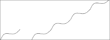
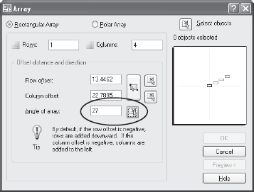
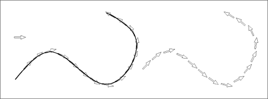
A rectangular array can be created at any angle by selecting the Angle Of Array option in the Array dialog box, even if you don't know the angle. Suppose you want to array the shape on the left in Figure 1.5 to form the shape on the right.
In the example, both the angle and the size of the object are randomly assigned. In other words, you don't know the exact size or angle, and you can't estimate because you want the result to have no gaps or overlaps of the objects as they're arrayed. You can approach this situation using two methods, one of which works with either the command-line version or the dialog-box version of ARRAY.
To create the shape in Figure 1.5, follow these steps:
Run the ARRAY command, pick the Select Objects button, and select the spline object.
Enter 1 for the number of columns and 4 for the number of rows.
Pick the Angle Of Array button shown in Figure 1.6; The dialog box will close temporarily to allow you to select two points in response to the prompt
Specify angle of array.Using the Endpoint object snap, select each end of the spline. Doing so returns an angle and places that value in the window.
Pick either the Column Offset or Unit Distance button, which results in the prompt
Specify distance between columns.Using the Endpoint object snap, select each end of the spline once again. Doing so returns a distance this time and places that value in the window. Click the Preview button; if you like the results, you're done.
You may decide to automate a process like this using AutoLISP. In that case, you need to follow these steps, using the command-line version of the ARRAY command:
Run the UCS command, and type
Z
Select the two endpoints of the object, in this case a spline, to indicate the angle of rotation.
Note
Any time you're prompted for a distance or an angle in AutoCAD, you can select points on the screen instead of typing them in. Doing so is both fast and accurate. When you start creating your own commands in AutoLISP, you can use specific functions to make your programs behave the same way.
Run the ARRAY command at the command prompt (
-AR), and select the spline you want to array at an angle.Press the Enter key at the
Enter the type of array [Rectangular/Polar] <R>prompt.Specify one row and four columns, and you'll be prompted to give the distance only between columns.
Select the two endpoints of the spline again to give the exact distance.
Use the UCS command to return to the World Coordinate System (WCS).
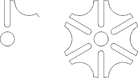
Geometry with a repeated angular pattern is often found in mechanical applications and sometimes in architectural and civil applications. To create polar arrays efficiently, avoid repeating the same set of editing operations for each feature arrayed. Start by identifying a repeatable pattern on the object. Draw the whole pattern once, and then array the result, rather than arraying each of the components of the pattern separately. Be careful. It's easy to select an extra entity when you use the Polar option of ARRAY. The result looks fine, but you have entities on top of each other. The image in Figure 1.7 illustrates an efficient technique for using polar arrays by identifying and creating the repeatable pattern before arraying anything. The repeatable pattern is shown on the left, and the result of doing a single array of that pattern is on the right. The alternative involves multiple construction lines and six times more editing for each feature.
After using ARRAY to create geometry from lines and arcs, you can determine whether the result is perfect using the PEDIT command. If you use PEDIT to join lines into a closed object, they can only be joined if they connect perfectly at all intersections. Your geometry is perfect if the first option of PEDIT, Close, changes to Open after you've joined all your lines. If the geometry isn't perfect (and sometimes that can't be helped), you can still join the segments into a single object using the MPEDIT command.
MPEDIT was once an Express Tool. It allows you to set a fuzz factor for combining lines, arcs, or plines into a single object. To use it, run MPEDIT, and then select all the objects you want to join. You're prompted for a fuzz factor. Enter a number that is greater than your likely error, and MPEDIT cleans up the mess. (I hope you're working on someone else's mess, because you should be able to avoid sloppy drawing if you use the accuracy tools available in AutoCAD.)
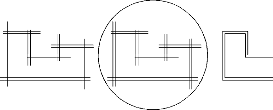
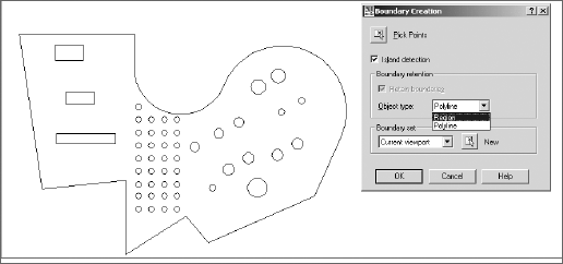
There are also some alternatives to PEDIT for finding areas, even if your closed geometry has overlapping lines. Using the BOUNDARY command, you can select a point and have a closed pline or a region created automatically. This works great for interior spaces, but you can use this command even in situations that are less obvious. For example, when you have overlapping construction lines and want to create a clean set of double lines (a floor plan, for example), use the technique shown in Figure 1.8: Enclose the entire group of lines with a circle, and select a point inside the circle but outside the lines.
You can create regions with the BOUNDARY command or with the REGION command. Either way, you can also use regions to create complex objects quickly by using the SUBTRACT, INTERSECT, and UNION commands. The shape shown in Figure 1.9 was created in under one minute (actually, 38 seconds).
To create regions from existing closed plines or circles, use the REGION command and select the objects. You can create a new object using SUBTRACT, UNION, or INTERSECT, and that object is also a region. If you need to work with individual lines or arcs, use the EXPLODE command to break the region into entities.
Note
If you have trouble understanding what a region is, think of it as a flat 3D object with a thickness of 0. The 3D Boolean editing commands will work with any region; the REGION command can be useful for other applications as well, including creating floating viewports in a layout.
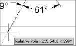
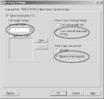
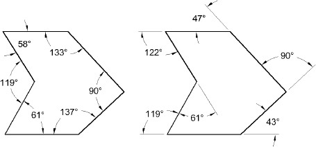
For many drawings, you know the length of each line and the angles between lines. However, you probably don't know the absolute angle of each line in the X-Y plane (angle from 0°–East). There is a strategy for doing drawings of this kind; it involves recognizing that supplemental angles form a straight line (180°). It also involves using the often-overlooked Relative option of AutoCAD's polar tracking feature.
Note
Note that in this case, Increment Angle is set to one (1). This is a small angle, and it isn't easy to work with, but it can be used. If the angles you're using are based on larger increments, use them. It's much easier to use an angle increment of 5, 15, or 45; but any increment can be typed into the window, including values so small they are completely unusable as angles. That's one of the things I love about AutoCAD. It doesn't restrict what you can do by overprotecting you from the results of commands.
Note
You can change the default direction of angles from counterclockwise to clockwise to do this kind of drawing when it's easier to draw clockwise. But if you change the angular direction from counterclockwise to clockwise to simplify drawing a single shape, make sure you change it back to avoid confusion later.
If you know that you need to start drawing an object a specific distance from an existing object, use the From osnap and the @ symbol. For example, if you want to start a rectangle 10 units over and 45 units up from an existing endpoint, do the following:
Start the RECTANG command.
Use the From osnap.
Select the starting point.
Type the coordinates for the first corner of the rectangle as
@10,45.
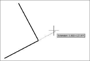
If you have POLAR, OSNAP, and OTRACK on, and the Extension osnap is set as a running osnap, you can pause over any running osnap, acquire a temporary tracking vector, and use it with direct-distance entry to quickly draw an object relative to another object. See Figure 1.12.
Even better, play with the Temporary Track Point osnap until you understand how to use it, because it allows you to chase points all over the screen by typing TT prior to acquiring a tracking point. The new tracking point is temporary until you actually select it. I use TT a lot, and if you haven't figured it out, it's worth trying.
Note
The @ symbol can be used by itself to select the last point you entered.
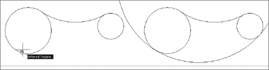
Another common shape involves tangent arcs. The quickest way to create an inside (concave) arc between two circles is to use the FILLET command with the proper radius set. However, an outside (convex) arc can't be drawn between two circles or arcs using FILLET. You must use the CIRCLE command with the TTR option and trim out the unwanted portion of the circle. The location of your cursor on the circles when you select tangent points determines whether a concave or a convex arc result. (See the Deferred Tangent tooltip in Figure 1.13.)
One overlooked feature of the FILLET command is its ability to quickly close two parallel lines with a tangent arc. Select both lines, and AutoCAD will calculate the size of an arc that it will use to join them on the end nearer your selection.
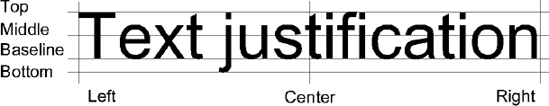
Most justification options are logical. Every line of text has four vertical locations for justification: Top, Middle, Baseline, Bottom, in that order. The Bottom is a line running through the lowest point on a lowercase letter with a descender (j, g, p, y). These locations are shown in Figure 1.14. The Justify options of DTEXT are [Align/Fit/Center/Middle/Right/TL/TC/TR/ML/MC/MR/BL/BC/BR]. The two-letter combinations match the locations: TL is Top Left, ML is Middle Left, and so on.
You can use geometry created in AutoCAD to get information accurate to 15 decimal places. However, the information you get out of AutoCAD is only as good as the accuracy of the geometry you create. Following are some tips on using inquiry commands.
It's easier to work with circle, pline, or region entities when determining areas, particularly if you're trying to add or subtract areas to get a final total. This section will give you some advice about using other entities to create plines or regions so you can easily find their areas.
You can use the PEDIT command to create a closed pline from several line and arc segments. To do so, issue the command, pick one of the lines, answer Yes when asked if you want to turn it into a pline, select the JOIN option, and pick the other segments with a window. Remember:
All segments must be touching but not overlapping.
You can't have segments on top of each other.
The resulting pline should be closed.
Use the Fuzz option of MPEDIT if your geometry isn't exact.
Note
The variable PEDITACCEPT was added to AutoCAD 2005. If it's set to 1, the user isn't prompted with the question Object selected is not a polyline. Do you want to turn it into one? <Y>. Instead, the object is automatically turned into a pline. It's possible that 1 will become the default setting in a future release.
When you use the AREA command, it's easier to select objects than it is to pick points. To find the area of a large object minus the areas of several smaller objects, you can use the Add and Subtract options of the AREA command. Pay attention to the command prompts. Type AREA
Note
The alias for the AREA command is AA, which doesn't follow the normal pattern used for other commands. Why not? A (ARC) and AR (ARRAY) are already taken. RENDER (RR) is the only other alias with this format.
It's not unusual to want to find the area of an object with a large number of features removed. It's easy to miss one or more objects in the process. The quickest way to get a total area when you have many areas to subtract is to create regions. If all the objects are circles or closed plines, you can do this with the REGION command. If the shapes are composed of anything else—lines, arcs, overlapping segments—use the BOUNDARY command. Once all the shapes are regions, use the SUBTRACT command to create a single region. Then you can select a single entity when using the Object option of the AREA command.
In Figure 1.15, it took 25 seconds to get the total area of the object with all internal shapes removed. Here are the steps:
Create regions from the existing geometry using the BOUNDARY command.
Use the SUBTRACT command to remove the holes from the large object by selecting them all with a window.
Use the Object option of the AREA command, and select the resulting region. You can also find the area as a property of the region in the Properties palette.
The DIST command gives you an accurate distance if you use object snaps to pick the points. It's also the quickest way to get an angle in the X-Y plane. Pick the points in the proper order, or the angle will be off by 180°. To get the angle between two lines, use DIMANGULAR (DAN). The lines don't have to exist; you can select three points with DIMANGULAR and get the angle between the segments defined by the points.
Both these commands give you information that varies by entity selected, including the arc length of an arc. PROPERTIES can be used to change the properties of multiple objects as well as individual objects. For example, you can change the height of all text in the drawing without changing the locations.
TIME gives you the total time during which a drawing has been open for editing. You can also use it as a running timer by selecting the Reset option before beginning something new. Use this timer as you try to develop more drawing speed. Pick one object, and draw it several times using different strategies. The TIME command can tell you if you're getting any faster. I've also used the TIME function to see if one computer in an office really is slower than another, or if it's just the perception of a frustrated user. See Chapter 7, "AutoCAD Scripts" for a benchmark system to test computers with no user input.
You can save drawing files using any of the following commands: SAVE, QSAVE, SAVEAS, and WBLOCK. Each of these commands creates a DWG file in different ways, but each has its own advantages:
SAVEAS When you select Save As from the pull-down menu, or type SAVEAS, AutoCAD saves to a specified path with a specified name and makes the resulting path and filename the default. The next time you use a save command, including QSAVE (Ctrl-S), this name and location will be used.
SAVE The SAVE command, if it's issued by typing at the command prompt, allows you to save to a different location or name without redefining the default drawing. (The Save option on the pull-down actually calls the QSAVE command. I change this whenever I upgrade AutoCAD.) I wish all Windows software had this kind of save option.
QSAVE The QSAVE (quick save) command automatically saves to the default location and name. Ctrl-S issues the QSAVE command.
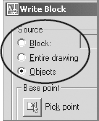
WBLOCK WBLOCK is a save command. It lets you save part of an existing drawing, using one of three methods. Select the option you want from the dialog box, as shown in Figure 1.16. Because dialog boxes can't be used in AutoLISP programs, you should know the command sequence for WBLOCK. When issued from the command line with FILEDIA turned off, the -WBLOCK command allows you to make the same selections. See Chapter 5, "Symbols, Tables, and Fields," for more information on the WBLOCK command.
Backup copies The best method for making backup copies to removable drives (CD, flash, DVD) as you're drawing is to type the SAVE command at the command line or use the Send To function of Windows. Otherwise, you redefine the default name and location. Right-click any filename in a windows file-management dialog box to select Send To. You can add a location by creating a shortcut and placing it in the folder C:Documents and Settings%username%SendTo. Replace %username% with your login name. See Chapter 2, "Managing Your System," for automated backup techniques.
GROUP The GROUP command should be used more often, in my opinion. It allows you to name a selection set so that you can use it again. Once a group is created, you can type G
PICKSTYLE The settings of the AutoCAD variable PICKSTYLE determine how other members of a group are treated, including associated hatch patterns, whenever any member of the group is selected. PICKSTYLE has four settings that you can toggle using the Ctrl-H keys (the Ctrl-A keys in AutoCAD 2000 and AutoCAD 2000i).
PICKSTYLE = 0 allows selection of individual members of the group.
PICKSTYLE = 1 allows the selection of the whole group but not boundaries.
PICKSTYLE = 2 groups the selection of hatches with boundary objects.
PICKSTYLE = 3 allows the selection of whole groups and group selection of associated hatches with their boundaries.
Note
If you find that a hatch boundary is erased when you erase the hatch, check your PICKSTYLE setting. It's probably set to 3.
One of the most underused editing functions in AutoCAD is the Properties palette. Some editing functions can be used in ways they weren't necessarily designed for, and there are other options that a surprising number of people overlook—most notably the Through option of the OFFSET command and the Reference option of the SCALE and ROTATE commands.
This command displays the Properties palette of selected entities. If more than one object is selected, the properties common to all are displayed. Properties of similar objects can be changed simultaneously.
Let's walk through an example. Let's say you have a drawing that has a lot of text. Every text entity must stay in its current location, but the height must change for all. At one time, that was a difficult problem, but not any more. Open the Properties palette, and click the Quick Select icon (the button with the funnel icon in the upper-right corner). Select text in the window, and all the text entities are highlighted (but not the MText entities). Now, change the text height in the Properties palette; the height of all the text changes. You can change any of the properties of the entire group. You could do the same for all the circles in a drawing or within a selection set, and change their diameters.
You can use either of these commands to clean up sharp corners or extend two unconnected lines into sharp corners by setting their values to 0. As of AutoCAD 2006, you have the following option: Hold down the Shift key while selecting the second line to create a sharp corner.
If you're having trouble snapping to what you think is an intersection between two lines, use FILLLET with a radius of 0, select the two lines, and then try again. If that works, you don't have to take the time to zoom into the intersection to see if there's a gap.
Note
You can quickly create a slot by selecting two parallel lines when prompted by the FILLET command.
These commands behave similarly. The difference is that DIVIDE results in an entity divided into a specified number of segments, all the same length. MEASURE divides the entity into segments of a given length, with one shorter segment (usually) at the end. Entities aren't actually segmented; instead, a point is placed at each division.
Note
The appearance of all the points in a drawing (except those on the Defpoints layer) is controlled by the variable PDMODE. You can set this variable using the Point Style dialog box.
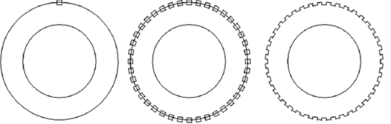
It's also possible with either DIVIDE or MEASURE to have a block inserted at each division instead of a point, which is a useful and often overlooked feature. You can quickly approximate a complex linetype, for example, by placing any block along a line, pline, or spline object. This works well for placing arrows on an egress map (see Figure 1.17).
You can use EXPLODE with the following entities: blocks, hatches, mlines, plines, solid objects, and blocks of text created with the MTEXT command. Any blocks can be exploded except those placed using the MINSERT command. For that reason, MINSERT should not be used unless you want a block that can't be exploded. When you use EXPLODE, be careful not to select more objects than you want.
Note
The TXTEXP Express Tool can explode individual pieces of text into vectors. The results aren't always pretty, but I've used this technique successfully to create cutting-tool paths for CNC machines used to mill letters in either metal or wood. The results differ between SHX fonts and TTF fonts. Shape fonts, which are vector-based, are exploded into line segments, whereas TrueType fonts are exploded into closed polylines. Usually a single letter requires multiple closed polylines that can be edited into a single outline.
Note
You can form 3D block letters by using TXTEXP to explode a TrueType font and then using EXTRUDE to create 3D solids out of all the segments used for each letter. Use UNION to create a single solid.
This command has always had two options: Distance and Through. The Through option allows you to offset an object through a selected point, even if the object isn't long enough to actually pass through the point.
AutoCAD 2006 added some nice features to OFFSET. You can offset an object onto the current layer. You can also elect to erase the source object after using offset. That sounds like it would just become the MOVE command, which it would, except that a multiple option was also added that lets you continue picking through points or offsetting the same distance multiple times.
People use UNDO sometimes when they really should use the OOPS command. OOPS can be used at any time to restore all the entities erased as a single selection set the last time the ERASE command was used. It doesn't have to be issued immediately after the entities are erased. More often than I should, I erase objects that are in the way of a delicate editing operation, and then I use OOPS to get them back after I'm done editing. I don't recommend this approach, but I do it.
Note
OOPS restores objects even if their layer is currently frozen or turned off.
The remarkably useful and often overlooked option of ROTATE is Reference. You can use the Reference option by entering any angle at the keyboard or by picking two points on the screen. You then type the angle to which you want the selected points to align.
Instead of typing the new angle, you can also make one more selection. It becomes the second point on a new angle, using the first point selected as a reference for a base point.
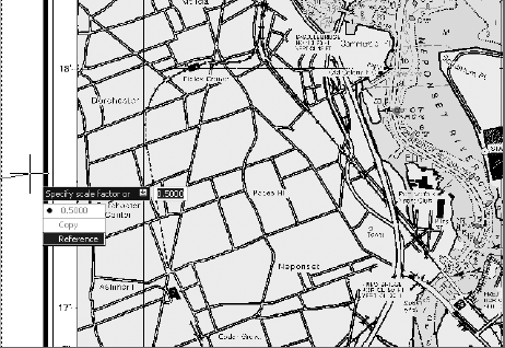
SCALE also has a Reference option that's similar to ROTATE's but that may be even more useful. I use it frequently to resize an image using a feature on the image that I know the size of—this can be a photograph of landscape, nautical charts, a mechanical part, or anything else that's not to scale when inserted. In the example in Figure 1.18, a National Oceanic and Atmospheric Administration (NOAA) nautical chart has been referenced as an image. Scaling it using the Reference options involves the following steps:
Select the edge of the image.
Give a base point.
Type
Ror use the down arrows to select Reference, as shown.Select a start point. In this example, the latitude line showing 17′ is the first point.
Select a second point. In this example, the latitude line showing 18′ is the second point.
Type 1 for one nautical mile, the base unit of this drawing. Because the distance from 17′ to 18′ is one minute of latitude, which represents one nautical mile on the earth, the image scales correctly.
The UNDO command displays the following options at the command prompt: Auto/Control/BEgin/End/Mark/Back<Number>:
Auto Auto requires an additional specification of On or Off. When Auto is on, any operation taken from the menu, no matter how complicated, is treated as a single command, reversible by a single U command.
Back Back takes the drawing back to the state it was in when the most recent mark was entered. If you don't enter a mark, the drawing goes back to the beginning of the editing session. AutoCAD automatically places marks when some commands are used, but normally you must place them yourself. You can place multiple marks and UNDO each.
Control Control limits the UNDO operation or disables it completely. It offers the following options:
All enables the full UNDO feature.
None disables U and UNDO commands.
One limits U and UNDO to a single operation.
BEgin and End BEgin and End cause a group of commands to be treated as a single command for the purposes of U and UNDO. A group, once ended, is always treated as a single, indivisible operation.
Note
This is useful when you're writing an AutoLISP program. Place an UNDO BEgin at the beginning of the program and an UNDO End at the end. If the user doesn't like what the program did, it only takes one U to undo it. Otherwise, a separate UNDO is required for each step executed by the AutoLISP program.
Mark Mark makes a special mark in the undo information, to which you can later back up with the Back option. If you're about to go off on a design tangent, you may want to set a mark with UNDO so you can return to that point quickly if the tangent doesn't work out.
Number Number (default is 1) specifies the number of preceding operations to be undone. UNDO 1 is the equivalent of the U command. When you use a different value, 20 for example, 20 operations are undone at once. Typing REDO restores all 20. Using this option allows you to search back through the drawing history (only during the current editing session) for a specific point in the design process by typing in large values. Don't forget to save the drawing before doing this.
Note
You can click the down arrow next to the Undo button to see a command history and select the command you want to go back to. The Redo button has a similar command history.
This interesting command can be used to change the length of a line, polyline, or an arc. It's the only way to quickly create an arc with a specific arc length. To do that, create the arc, and use the Total option of LENGTHEN to change the total length to whatever you want.
LENGTHEN's options include the following:
DElta DElta allows you to add a specific amount to the length of an existing line or arc, or to add a specific angle to the existing included angle of an arc.
Percent Percent allows a specific percentage increase in the length of a line or pline or the included angle of an arc.
Total Total lets you set a new overall length for a line, a pline, or an arc.
DYnamic DYnamic allows you to change the length of a line (but not a pline) or the included angle of an arc by picking a new point and watching it change.
<Select object> <Select object> gives the existing length or angle of a line or arc.
Dimension styles are discussed at length in Chapter 4 because they're critical to applying technical graphics standards correctly. Here I want to point out some aspects of the process of dimensioning that people often get wrong, starting with a difference that almost nobody seems to understand: aligned versus rotated dimensions
In my experience, most users don't understand rotated dimensions. All linear dimensions are either aligned or rotated, but most are rotated. Vertical dimensions are rotated to 90, horizontal dimensions to 0. Because those angles are built in, users often overlook the possibility of rotating dimensions to other angles and frequently attempt to use an aligned dimension where a rotated one is needed. Figure 1.19 shows the problem with trying to use DIMALIGN.
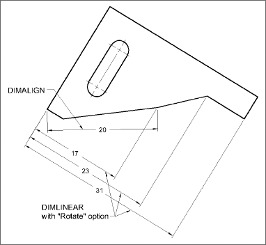
To place a rotated linear dimension between two points at any angle, use DIMLINEAR and select the Rotated option. You can specify a rotation angle directly or by picking any two points that are at the desired angle of rotation.
Ordinate dimensions are used to set dimensions as coordinates in the X and Y axes. Ordinate dimensioning is used most often in mechanical drawing, but it's increasingly being used in architectural and other fields as well. When I draw a structure that I'll be building myself, I always dimension it with ordinate dimensions rather than with continuous dimensions, which is the traditional method. That way, I can hook a tape to one end of a sole or top plate and mark all locations of openings from a fixed point.
Although there's a DIMORD command, the quickest way to place ordinate dimensions is with QDIM. Select the points you wish to dimension, and then select a new datumPoint for 0,0. Now you can choose the Ordinate option, select your objects, and place all ordinate dimensions with one pick. If you have objects with different base points, use the datumPoint option again.
Note
To facilitate the use of ordinate dimensions, you can place points using the POINT command at every location you wish to use as an origin. Using either the FILTER or QSELECT command, you can now select only points. Doing so prevents you from inadvertently selecting too many objects.
If you don't use QDIM, you must first establish a new base point by setting a UCS with its origin at the 0,0 location on the part you're dimensioning. Use the UCS command, select the Origin option, and then select the 0,0 point on the part. If UCSICON is ON and set to ORigin, the icon representing the UCS moves to the new origin point. AutoCAD automatically places the correct distance in the X or Y direction, depending on which direction you move from the dimension origin point you pick.
These dimension values are associated with defpoints, not the objects themselves, if DIMASSOC is 1 or 2. This association is maintained for the UCS that was current when the dimension was placed. Stretching the defpoints of the dimensions results in the values being updated correctly, even if a new UCS has been set since the dimension was created.
AutoCAD 2007 includes 79 dimension variables. The easiest way to change them is using the Dimension Style Manager dialog box. You don't have to know all of them, but there are two you should understand.
This variable was added to AutoCAD 2002 to control associative dimensions. It replaces DIMASO, but not completely, because earlier drawings can be opened in current releases. When an earlier drawing is opened, the setting for DIMASO is used to determine the value of DIMASSOC.
0—Dimensions are exploded as they're placed, which is a bad idea unless you have a very good reason.
1—Dimensions have the traditional defpoint association, but they're not associated with objects and aren't connected to Model Space when a dimension is placed in Paper Space.
2—Dimensions move with objects and reflect true size when placed in Paper Space.
This variable controls all size dimension variables, such as DIMTXT, DIMASZ, DIMEXE, DIMEXO, DIMTVP, DIMTSZ, and DIMGAP. In the past, for Model Space plotting, DIMSCALE was set to the reciprocal of the plot scale to be used. If plotting will reduce a drawing 48 times to fit on a sheet of paper, you must first increase the size of the dimensions 48 times so they'll be readable. DIMSCALE is set to 1 if dimensions are placed in Paper Space (which I don't recommend).
The system that I do recommend is to place dimensions in Model Space and to plot from Paper Space. For that purpose, setting a DIMSCALE of 0 before dimensioning allows you to add dimensions in viewports with different zoom magnifications and have them all come out the same size. Select Scale Dimensions To Layout in the Dimension Style Manager dialog box on the Fit tab. See Chapter 6 for detailed information on plotting.
Note
Many offices still use the once-standard practice of setting DIMSCALE to a value that reflects the reciprocal of the plot scale. This is a legacy of the old days of AutoCAD when such practice was required. If you choose to change this practice, you should do so in the context of a complete overhaul of office standards. Such an overhaul should, of course, include all affected parties.
This section discusses some of the system variables (the setvars) in AutoCAD, but certainly not all of them. What follows are the settings that people sometimes overlook or that I have specific recommendations about.
System variables control the appearance or behavior of AutoCAD. You normally set these by making a selection in an appropriate dialog box, but they can also be set from the command line. Old-time users probably do this a lot by typing the variable name quickly. If I want to change my linear unit precision to check something, I type LUPREC and then type 8. When I have the information I want, I undo that action or type LUPREC again.
Not everyone can touch-type; however, I appreciate being able to. (This may be a good time to thank my mother for insisting that I take high school typing in 1967—an era when the manual typewriters used in classrooms had blank keys so you wouldn't hunt and peck.)
The OPTIONS command (see Chapter 2, "Managing Your System") allows you to set all drawing aids, file search paths, the appearance of the screen, and the variables affecting saving and opening drawings, and also lets you save these settings in a user profile. The profiles can be exported for use on other computers.
Note
There has been pressure over the years to eliminate the AutoCAD command line because it's seen by some people as outdated. I've always found this suggestion alarming, because a keyboard jockey can be much faster and more efficient than a toolbar user with comparable skills. For us keyboard users, Autodesk's decision to make the command line one more optional aspect of the interface was a welcome response to this pressure.
The APERTURE variable allows you to control how close you must be to an object, measured in pixels, when using an osnap. It can also be set using the Drafting tab of the OPTIONS dialog box. If you're having trouble isolating an object in a cluttered area, try setting this value to a smaller size—I prefer a setting of 3. If you're having trouble picking an object because you have to get too close to it, try a larger size.
PICKBOX is similar, but it controls the size of the box that shows up when you're asked to select an object for editing. You can also control it visually using the Drafting tab of the OPTIONS dialog box. I like a setting of 3 for this one, as well.
In the past, it was common to set this variable to the reciprocal of the intended plot scale. If you use layouts properly, however, you shouldn't use LTSCALE to control the appearance of linetypes, because it's global and affects all lines in a drawing. Instead, set LTSCALE, CELTSCALE, and PSLTSCALE all to 1 and ignore the appearance of your linetypes until you set up a layout. With PSLTSCALE set to 1, your linetypes scale automatically in Paper Space, so they plot the same regardless of the ZOOM factor used for the viewport in which they appear.
Note
Some people don't like drawing in the Model Space tab unless their linetypes display correctly. I don't think it should matter. If you put entities representing each linetype on a different layer and use different colors for those layers, you can easily identify the type of line it represents without seeing the segments. Once you have a layout, everything will look great.
If some of your entities have linetypes that aren't scaled to your liking, instead of changing that with LTSCALE, use PROPERTIES to make changes to each individual object in a viewport in the layout.
Note
Linetype problems are often the result of confusion between metric and imperial units. If you need an LTSCALE of 25 or so to see linetypes properly in a layout, you've probably started your drawing in imperial units but are drawing objects measured in millimeters. If you need a small setting, say .04, then it's likely that you have the opposite problem: You started a drawing in metric units but are drawing in inches. See the earlier section "Control Imperial vs. Metric Units."
A number of things about layers can give you problems. Here are a few of them:
Locking allows you to lock a layer so that it's visible but not changeable. You can still use osnaps on the visible entities. Most users would benefit from using layer locking more often to avoid inadvertent changes to their drawings.
Note
People sometimes confuse layer locking with viewport locking in a layout. They do different things and aren't related. Locking a layer doesn't affect the display of objects in any way. Locking a viewport doesn't prevent you from changing objects in that viewport.
Layer filters, and freezing layers by viewport (VPLAYER) are useful advanced commands in the Layer Properties Manager dialog box.
You can change layer names in the Layer Properties Manager dialog box; but the RENAME command is faster when you're changing names of layers from a bound XRef, because you can use wildcards. Layer 0 is the only layer you can't rename.
Plot/No Plot settings can be made for layers, so there's no longer a need to use the Defpoints layer for that purpose. Don't make Defpoints the active layer, because any objects you add to it won't plot.
Note
I've seen two cases of odd behavior with objects placed on the Defpoints layer: One user was unable to select a viewport even though it was visible, and another placed points on that layer but couldn't change their appearance. In the viewport case, freezing layer 0 created the problem. And points can't be displayed as anything other than a single pixel on the Defpoints layer. The only reason to place objects on the Defpoints layer is the security of knowing that no one will accidentally plot them.
I'm sure you frequently use the All, Extents, and Window options of the ZOOM command, but have you ever saved the results with a name so you can return to it quickly? If you have to connect two small features that are widely separated, have you ever used VPORTS to place two views in the Model Space tab and drawn from one to the other? Read on.
It surprises me how few people use this feature. It allows you to save a specific view on the screen, or as defined by a window, so that you can immediately call it up later. This approach reduces the number of regenerations necessary. It's particularly useful in 3D drawings, and some people use this feature for plotting a specific view. If you haven't ever tried saving named views, try it. You'll be surprised at how useful it can be, particularly when using AutoCAD sheet sets.
This function is essential in 3D drawing and often useful in 2D drawing as well. It allows you to divide your screen in Model Space into multiple views. In 3D, this permits you to create geometry while seeing it in a front, top, right side, and iso view. You can then have a different UCS in each viewport and get a different view of the same geometry.
To create a set of standard views for 3D, select the 3D option in the Viewports dialog box. Don't forget to use the SAVE option to save a configuration you've set up. Don't confuse saving viewports with saving views. You can restore saved views within any Model Space viewport and then save the viewport configuration. Now, whenever the viewport configuration is restored, it will contain the views exactly as they appeared when the viewport was saved.
Roll the middle wheel away from you to zoom in or toward you to zoom out. The increment is controlled by the variable ZOOMFACTOR—the larger the value, the bigger the jump when using the wheel. If you hold down the scroll wheel, you can pan. If you hold down the wheel while holding the Ctrl key, you get a joystick pan—not that useful, but kind of fun.
Note
Because holding down the middle wheel allows panning in all directions, the Windows scrollbars aren't useful and often get in the way. Turn them off under the Display tab of the Options dialog box, and you'll get a 4 percent increase in screen area. If you paid $400 for your monitor, that's like getting $16 just for changing a setting!
AutoCAD 2006 added a view transition feature that smoothly changes magnification or location when zooming or panning. This replaced the abrupt transitions of prior releases. Some people love it, and some people don't. VTENABLE allows you to turn it off for everything, for panning only, for zooming only, for scripts only, or for some combination. The VTFTS and VTDURATION variables control the threshold and speed of the transition. Personally, I turn it off to speed things up a little.
Utilities allow you to do things like rename files and purge unused layers. There are just a few things here, but one that could be a huge timesaver is the use of wildcards in the RENAME command, particularly when you bind an XRef.
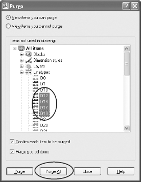
The PURGE command is used to selectively remove unused layers, blocks, styles, linetypes, and dimstyles. You can do this by name or using the Purge All option (ALL at the command line). If your drawing has nested block definitions (blocks used to create other blocks), you can select Purge Nested Items starting with AutoCAD 2002. In earlier releases, use the PURGE command as many times as there are levels of nesting in your block definitions in order to ensure that you're purging everything. The Purge dialog box also allows you to select individual entities individually or in groups. To select a consecutive list of entities, select the beginning item, hold down the Shift key, and select the last item in the group. The Ctrl key lets you add or remove items from the selection set. See Figure 1.20.
Many people still use the WBLOCK command as a quick and complete PURGE command. That requires you to use the Entire Drawing option in the dialog box for WBLOCK, or the * option at the command line.
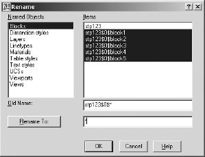
This is a great way to rename blocks, dimension styles, layers, linetypes, materials, table styles, text styles, UCSs, views, and viewports. You can use wildcards, allowing you to quickly change all names created when binding external references (if you used the Bind option for binding, which I recommend you do, and not the Insert option). For example, if you bind an externally referenced drawing named STP123.dwg to a host drawing, the block definitions have names like STP123$0$BLOCK1, STP123$0$BLOCK2, STP123$0$BLOCK3, STP123$0$BLOCK4, and STP123$0$BLOCK5. If you want them to have the names BLOCK1 and so on, type STP123$0$* in the Old Name field and * in the Rename To field, as shown in Figure 1.21.
You can elect to open part of a drawing to reduce regeneration time on large drawings. Highlight a file and then select the Open button in the lower-right corner of the Select File dialog box that's used to open an existing drawing. The Partial Open dialog box that's displayed can be used to select only those layers or views with which you want to work. Once you've used PARTIALOPEN to open part of a drawing, you can use the PARTIALLOAD command (found on the File pull-down menu) to select different layers. There is a design flaw in PARTIALLOAD: You must reselect all layers each time you do a partial load. The layers you first selected aren't remembered. This issue wasn't addressed in AutoCAD 2007, but I'm hoping it will be fixed someday.
The Express Tools, which started as Bonus Tools, have always been popular with AutoCAD users. Many users haven't found them or haven't taken the time to understand them, or these tools aren't loaded on their workstation. Some afternoon when you have a little time, go to the Express pull-down menu and select Help. Now you can read about each tool and get inspired:
Note
If you don't have the Express Tools loaded on your workstation, try typing the command EXPRESSTOOLS at the command line. They may show up. If they don't, the tools may not have been loaded by whoever installed AutoCAD. This is likely to be the case if you use Architectural Desktop (ADT) prior to Release 2007, because loading Express Tools isn't listed as an option during the install. You have to have the install CD, know where on the CD the Express Tools are stored (a folder named Express), and then load them manually. This is because CHSPACE will corrupt some pre-Release 2007 ADT objects.
This command is indispensable, and it has finally evolved from an Express Tool into a native command in AutoCAD 2007. It lets you change objects between Paper Space and Model Space while retaining their relative scales. This makes it possible to place text or dimensions wherever it's convenient while working and then move them to their permanent home later. If you ever decide you placed something in the wrong space, you need this command.
LAYWALK This tool allows you to walk though the objects on various layers to give you a visual clue as to what you've placed where. It's valuable when you're dealing with someone else's disaster drawing. The objects on each layer are isolated temporarily while you cycle through the layers. Like CHSPACE, LAYWALK is now a native command in AutoCAD 2007.
TXT2MTXT TXT2MTXT is used to combine individual lines of text into a single MTEXT object. It doesn't format the final result as individual lines, so you almost always need to do some editing; but if you want to group text from older drawings into a single object, it's nice.
FLATTEN I've recommended this command to a lot of people in companies that do civil design. They call me because they're having trouble with a drawing from someone else. Object snapping to endpoints produces odd results because, it turns out, the elements aren't all at the same elevation. FLATTEN quickly and thoroughly places every object at an elevation of zero.
MKSHP and MKLTYPE These commands give you the ability to create complex linetypes: those containing text or shapes. This process requires that a shape be created first (MKSHP) and then the linetype (MKLTYPE).
LAYMERGE I often advise new users and companies to use as many layers as they may need so they'll have control over the related elements of a drawing. Sometimes this results in too many layers, which is always easier to fix than too few. When you do have too many layers, this command lets you put them together into one. This is another of the Express Tools that have become actual commands.
DIMEX and DIMIN These are related commands that allow you to export dimension styles and then import them into a different drawing. You can do this through AutoCAD DesignCenter or by inserting a drawing that contains the dimension style, but these Express Tools make it a little easier.
DIMREASSOC This is a nice tool. It permits you to individually or globally update dimensions that have been overridden by the operator. In other words, the value in the dimension and the actual size of the object don't match. My favorite application of this command is to find any dimensions that were overridden. I have overridden a dimension purposely on rare occasions when I had an imminent deadline and had to plot something out immediately. With DIMREASSOC, I can find those places and go back and fix the geometry.
You can also change the overwritten dimensions automatically, which may cause even more problems if you don't notice what got updated. The problem is that the value is probably overridden because the geometry is wrong.
SYSVDLG The System Variables editor is a wonderful tool. It gives you a concise list of each system variable, tells you where its value is stored, and describes what it does. The best thing is that you can save the settings to an SVF file and restore them if you ever have to. If you do any training using computers that aren't your own, take this file with you; it will reduce the number of surprises you may encounter.
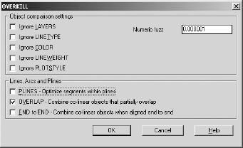
OVERKILL This command gets rid of overlapping lines, line segments that connect in what appears to be a single object, and duplicate objects on top of other objects. It can clean up a mess of a drawing in a hurry; see Figure 1.22.
Note
OVERKILL doesn't always work correctly. I've found that it works best if you use it for one kind of cleanup at a time (pline, overlaps, end-to-end) even though the dialog box allows you to check every type at once. Run it for each type separately to get the results you want.