
CHAPTER 3
Walls and Curtain Walls
Walls in Revit can range a great deal in complexity. Early in the design process, walls and curtain walls can be more generic, vertical containers for space and function. But they can also be associated to masses in order to create incredibly complex shapes. As the design progresses, these generic walls and curtain walls can be swapped out for more specific vertically compound walls that indicate a range of materials as well as geometric sweeps and reveals.
In this chapter, you learn the following skills:
- Creating generic walls
- Creating numerous wall configurations
- Modifying walls
- Creating curtain walls
- Modifying curtain walls
- Understanding basic wall parts and parameters
Creating Generic Walls
![]() The first thing you want to do is understand how walls generally work and how you should modify them. The challenge is that during the design process there's a lot that is not known (and probably can't be known), which can lead to a lot of unnecessary confusion.
The first thing you want to do is understand how walls generally work and how you should modify them. The challenge is that during the design process there's a lot that is not known (and probably can't be known), which can lead to a lot of unnecessary confusion.
Revit uses a system of “Generic” walls that in most cases are not made of anything specific. They're simply about the right thickness for the eventual condition. We recommend using these generic walls during the design process, and then swapping out these walls for more specific geometry later.
By default, the generic walls that have no specific structure are visually identical to walls that contain structure and finish layers. So it's a great idea to make your design walls visually unique. This way, you'll know what has to be swapped out for more specificity later. And there are also some more advantages, such as giving your walls transparency, that will help you quickly and easily visualize your design.
Let's start by giving our generic walls a material assignment that can be used to distinguish them from more specific wall types:
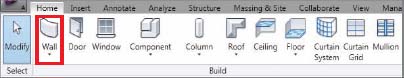
- Go to the Home tab on the ribbon and select the Wall tool from the Build panel (Figure 3.1).
FIGURE 3.1 Choose the Wall tool from the Build panel.
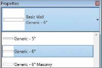
- Now select Basic Wall Generic – 6″ from the Properties menu (Figure 3.2) and sketch a west to east 20′-0″ (6.1 meters) portion of a wall. Don't worry about any of the other settings for the time being. When you're done, go to the Default 3D View, from the Quick Access toolbar.
FIGURE 3.2 Generic 6″ wall from the menu and the wall in 3D
- Select the wall and look at the properties. As you can see, there are a lot of values that apply to this particular piece of wall. You can change its height, constraints, and many other values (we'll get to most of them later). For now, let's create a unique Type property for the wall's material.
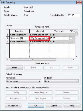
- Select the Edit Type option to open the Type Properties dialog box for the wall. To the right of the Structure label, click the Edit button. Select the <By Category> field, as shown in Figure 3.3.
FIGURE 3.3 Select the Material Field.
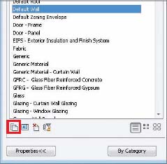
- Rather than create a material from scratch, let's duplicate something that is close and then modify it. Scroll down to the Default Wall material and then select the Duplicate option, as shown in Figure 3.4. Name the Material Generic Material and then click OK.
FIGURE 3.4 Duplicating the wall material
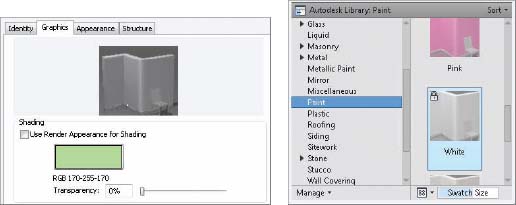
 Once you click OK, you will have a new material that you'll be able to replace with other rendered and shaded values. Click the Replace button on the Render Appearance tab. On the Graphics tab, set the Shading value as shown on the left in Figure 3.5 by selecting the colored panel. Then select the Appearance tab in Figure 3.5 to assign a newly rendered material, as shown on the right in Figure 3.5. This material will be useful for any design elements (floors, ceilings, roofs, etc.) that are used to resolve the design intent when you're not sure of the specific design content.
FIGURE 3.5 Assigning the material
DESIGNING GENERIC ELEMENTS
Generic elements play a large part in Revit. When you're creating your design, it's not practical to use lines to represent ideas when you can use content. But if you select something that's too specific, you might become frustrated. A design that is too specific too early has the tendency to be “exactly wrong.”
“Design” elements and materials help convey the intent of your design with the added benefit of scheduling, so that the data about a project is headed in the right direction without distracting anyone. They'll help you emphasize “where” something is as well as some of “what” something is without getting into the detail of how it's supposed to be assembled—until the time is right. Most of the frustration in design comes from working specifically to generally, rather than the other way around. Design elements will help you avoid this trap.
The Shading and Rendered values don't need to be the same. And in this case it's really helpful if they're not. When you use a white rendered material, you'll get a neutral, matte rendering. But changing the Shading value will help you quickly distinguish between design intent and more specific resolved elements.
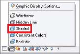
Click OK in all open dialog boxes until you're back in the project environment. Set the view to Shaded With Edges, as shown in Figure 3.6. Now you can quickly and easily tell your design elements from more specific selections.
Creating Numerous Wall Configurations
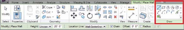
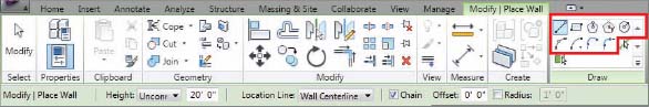
Now let's return to our Level 1 Floor Plan view and start creating a number of wall configurations. Pick the Wall command and you'll notice that a number of configurations are available for creating walls (Figure 3.7).
Sketching Walls
Walls are sketched by drawing the various configurations. These options are available in Figure 3.8. Take a moment to go through each of the sketching and editing options so that you become familiar with the results—particularly when drawing curved sections. The option to keep concentric is very important. Creating tangent arcs takes particular care as well.
FIGURE 3.8 Wall configurations that can be sketched
CREATING ELLIPTICAL WALLS
Since creating elliptical walls often comes up, we'll get it out of the way and give you the answer in two parts. First, elliptical walls can't be sketched as a singular element. And second (more importantly), they can be created via other workarounds (like creating elliptical masses and then picking the face of the mass to create elliptical walls).
The reason is that documenting the elliptical walls is difficult. There's no center to locate, and the arcs are continually changing in plan.
So what's a better way? Create the ellipse from a series of tangent arcs. Doing so will give you an approximation that is indistinguishable from an actual ellipse, and you'll be able to guide a more exact construction.
And if you don't know how to create an ellipse, just look around the office and ask for the person who used to design buildings with pencils. And after they tell you how, expect them to walk away snickering a bit at your expense.
Picking Walls
You can also create walls by picking lines. This approach is helpful if you have a CAD file that needs to be converted to a BIM model, or if the designer has created a single line design in another tool (like SketchUp) and expects you to use the exported results to start from in Revit.
Start by creating a few model lines. Click the Model Line tool, as shown in Figure 3.9.
FIGURE 3.9 Picking model lines

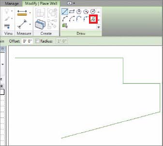
Now draw a series of lines that resembles Figure 3.10. Now that you have a few lines in your project, you can create walls using these lines with the Pick Lines tool (highlighted in Figure 3.10).
FIGURE 3.10 Sketching model lines
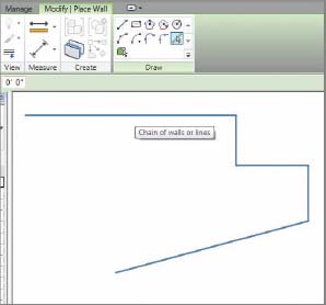
You have two options. You can create walls by picking single lines one at a time. Or, you can hover over one line and then press and release the Tab key. Doing so will highlight the chain of lines, as shown in Figure 3.11. Now you can pick the entire chain of lines to create a chain of walls.
FIGURE 3.11 Selecting a chain of lines
Hosting Elements in Walls
Walls can host elements that are meant to create openings. As long as the walls exist, the elements they are hosting will exist as well. Doors and windows are two common hosted elements.
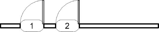
Placing a door in a wall is very easy and can be done in plan, elevation, or 3D views. In this exercise, you'll place doors from the Level 1 view. You'll use the very first wall that you created at the beginning of this chapter. From the Home tab, select the Door tool from the Build panel.
As you hover over walls, you'll notice that you're able to place doors in them. You're also shown temporary dimensions that will help you place the door closer to its correct location. Go ahead and place two doors as shown in Figure 3.12. Notice that by default Revit will tag the door number for you.
FIGURE 3.12 Hosting Doors in Walls
As mentioned earlier, walls can also host windows. Start by selecting the Window tool from the Home tab on the Build panel. Hover over the same wall and place a window as shown. As with any hosted elements, you'll only be able to place them within a host (Figure 3.13).

Containing Spaces
Walls (and a few other elements) may also contain space. This is essential for creating space plans and tracking other room information in your project. But first the walls will have to be organized so that they can contain a space:
- Sketch additional walls to add to the walls that you created in the previous section so that the series of walls resembles Figure 3.14.
FIGURE 3.14 Enclosed series of walls
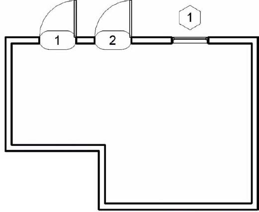
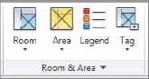
- Now that you have a series of walls, you can select the Room function from the Room & Area panel shown in Figure 3.15. Doing so allows you to add spaces to enclosed areas.
FIGURE 3.15 Selecting the Room function
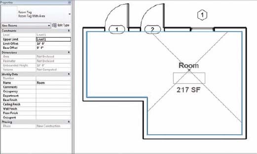
- Select Room Tag With Area from the Properties menu and then hover over the enclosed space. The extents of the space will highlight along with a room tag. Select the room tag and change to one that indicates the area. Then place the room and tag in the space (Figure 3.16).
FIGURE 3.16 Placing the room and room tag
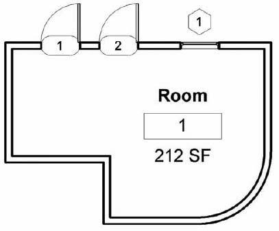
What's really great is that when the shape of the room changes, the area reported will immediately update to reflect the new space. Return to the Wall tool and use the Fillet Arc tool to fillet the lower-right intersection of the walls. The room area will update as shown in Figure 3.17.
FIGURE 3.17 Room tag with updated area
Modifying Walls
Now that you've created a few wall configurations, it's important to understand how you can modify them. Sometimes this is done simply by selecting the wall and dragging a wall end or a shape handle to a new position. In other cases, you want to be more exact and assign a specific value.
Your approach depends on where you are in the design process. Just remember that you can update design decisions and all your views, schedules, tagging, and so forth will update. So don't get too concerned with being too “exact” early in your design.
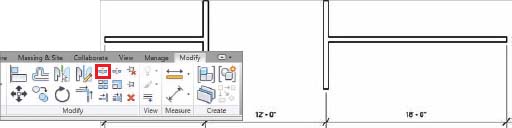
Start by sketching another straight segment of a wall, but this time as you draw the wall, type 40 (or 12 meters). Depending on the default units, typing 40 will create a 40′ segment. Notice that you didn't have to indicate the units “feet.” If you wanted to indicate “inches,” you'd only have to put a space between the first and second values. So 40′-6″ can easily be entered as “40(space)6”.
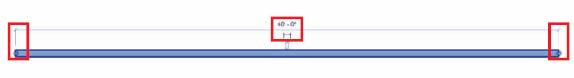
To modify the length, select the wall. You'll notice there are three options (Figure 3.18). You can type in a new value by selecting the temporary dimension, or you can simply drag either wall end to a new location.
FIGURE 3.18 Modifying the wall length
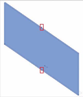
Now let's go to the Default 3D View and look at some other options. The highlighted areas of Figure 3.19 are called shape handles. You can press and drag them to adjust the top and bottom locations of a wall. As you drag the shape handle, the new location will be shown, whereas the existing location will be “ghosted” until you release the Shape Handle.
FIGURE 3.19 Wall shape handles
Instance Parameters
In many cases you'll want to enter more exact values, or just have more specific control over a particular wall instance. You can do this through the Instance Parameters menu (Figure 3.20). Select the wall and look at the properties.
Location Line The location line is the “origin” of the wall, and if you swap one wall for another, the location line will be maintained.
Base Constraint The base constraint is the bottom of the wall. Be careful! Deleting a constraint (in this case Level 1) also deletes what is associated to the constraint!
Base Offset The base offset is the value above or below the base constraint. So if you wanted a wall associated to Level 1 but 3′-0″ (1 meter) below, the value would be −3′−0″.
Base Is Attached The Base Is Attached value will allow you to automatically attach the bottom of a wall to the top of another wall, floor or roof.
FIGURE 3.20 Instance Parameters
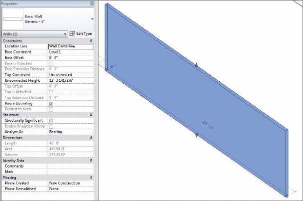
Unconnected Height The Unconnected Height value is the height of the wall. You can type in a specific value, but in this case the value is pretty irregular because we've manually dragged the shape handle to the new position.
Top Constraint The top constraint is presently shown as Unconnected. It can also be associated to Level 2, for example. This way, the wall will move vertically up or down if the level moves. For example, setting the Top Constraint to Level 2, the Unconnected Height will immediately reset to that value.
Top Is Attached Top Is Attached allows you to automatically attach the top of the wall to the underside of a wall, floor, or roof.
Room Bounding The last value you should be aware of is the Room Bounding option. Walls often are meant to contain space and remain space aware. This is what happened when you placed the Room tag in a previous exercise. But if you have a situation where you don't want walls to define a space, you can deselect this option and the Room tag will ignore the walls.
Editing and Resetting Profiles
Of course not all walls are rectilinear in elevation. For these situations you can edit the profile of a wall. Note that you'll only be able to edit the profile of a straight wall, not curved walls.
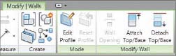
- Start by selecting the 40′ wall and selecting Edit Profile from the Modify | Walls tab (Figure 3.21).
FIGURE 3.21 Editing the profile for walls
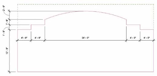
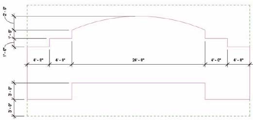
- From a South Elevation view, create the internal sketch as shown in Figure 3.22. Don't worry about dimensioning the sketch. We're just showing the dimensions for reference. Now delete the top line and fillet the two side sketch lines (Figure 3.22). Note that the reference lines indicating the extents of the original wall will remain.
FIGURE 3.22 Adding new sketch lines
- When you are done, click Finish Sketch Mode.
Attaching and Detaching Top and Base
We've previously attached the top of a wall to a roof. But walls can also be attached to the top or bottom of other walls. Let's do this with a copy of the wall from the edit elevation example.![]()
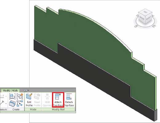
- Copy the wall off to the side, select it, and then click Edit Profile. Modify the exterior sketch as shown in Figure 3.23. Don't forget to trim and delete unnecessary sketch lines. Then finish the sketch.
FIGURE 3.23 Edited wall profile
- Now return to your Level 1 Plan View and sketch another wall right on top of the same location of the wall you just edited. But in this case, use a Generic 12″ wall. The walls will overlap and that's okay.
- Select the lower 12″ wall and then click Attach Top/Base (Figure 3.24). Now select the wall with the profile that we just edited. This will attach the top of the 12″ wall to the underside of the other wall, as shown on the right side of the figure.
The great thing about this technique is that relationships between the two walls are maintained if you edit the elevation profile of the upper wall. Performing these steps is a lot faster than having to edit the elevation profile of both walls!
Resetting Profiles
One last thing about editing wall profiles: If you need to remove the edited condition, don't reenter Edit Profile mode and manually remove the sketches. Select the wall and click Reset Profile in the Mode panel on the Modify | Walls tab. Doing so will reset the extents and remove any interior sketches.
Cutting Openings
Openings can be cut in both straight and curved walls. But the command tends to get used in curved walls because you already have the option to edit the elevation profile in straight walls. And when you cut an opening, you're not able to sketch beyond the extents of the wall boundary or create shapes that are not rectilinear. Here are the steps to create a rectilinear opening in a curved wall:
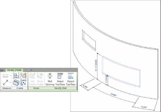
- Start by creating a curved wall segment and then go to your Default 3D View and select the wall.
- The Wall Opening option will then appear on the Modify | Walls tab, as shown in Figure 3.25 on the left. Select this command and then hover over the wall; you'll be prompted to create a rectilinear opening, as shown on Figure 3.25 on the right. To delete an opening, hover over the opening, select it, and then press the Delete key.
FIGURE 3.25 Creating wall openings
Splitting Walls
Sometimes after you've created walls you realize that you don't need an inner segment—or you need to change a segment to another wall type. Having to delete and re-create walls would be tedious. Revit allows you to split walls, effectively breaking them up into smaller pieces. This can be done along both horizontally and vertical edges of either curved or straight walls.
Let's experiment with this technique by creating a plan configuration of walls, as shown in Figure 3.26. The dimensions are shown for reference.
FIGURE 3.26 Configuration of walls
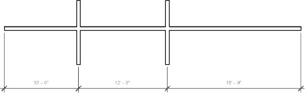
In this case the section of wall between the two parallel walls is not needed. But rather than delete the wall and create three new walls, let's split the wall twice and delete the inner wall.
- Select the Split Element command from the Modify tab.
- Hover over the location of the wall that you intend to split. You'll be prompted with a reference line that helps indicate to you which wall you're splitting. Split the wall twice at each intersection.
- Delete the inner segment. Your wall will now resemble Figure 3.27.
FIGURE 3.27 Using the Split Element command
Swapping Walls
![]() Swapping walls keeps you from having to delete them and start over. You can do the same thing when changing walls from one type to another. Doing so is as easy as selecting a wall and then selecting the new type from the Properties palette.
Swapping walls keeps you from having to delete them and start over. You can do the same thing when changing walls from one type to another. Doing so is as easy as selecting a wall and then selecting the new type from the Properties palette.
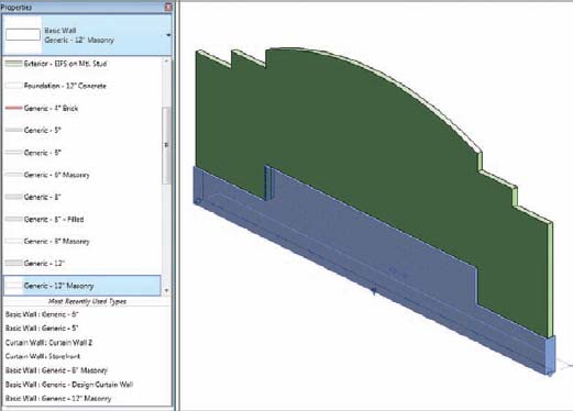
- We'll use the wall from the section, “Attaching and Detaching Top and Base.” Select the lower wall and then associate it to a new type.
- Change the lower wall to Generic – 12″ Masonry. Once you select the new wall type, the result will resemble the wall in Figure 3.28. Note that the patterns of the individual CMU courses are shown on the new wall's surface.
Creating Curtain Walls
Curtain walls are created in much the same way as regular walls: by selecting the type of curtain wall and then sketching the desired shape. But the available parameters are rather different. Let's start by creating a 40′-0″ (12 meter) section, using Curtain Wall 1 as the wall type.![]()
Grid Lines
Before adding mullions, we need to add grid lines to the curtain panel to which the mullions can associate.
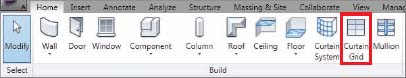
- Select the Curtain Grid tool from the Build panel (Figure 3.29).
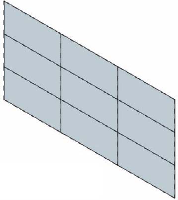
- As you hover over the edge of the curtain panel, Revit will prompt you with a dashed line that indicates the grid location. Also notice that the grid location gets kind of “sticky” at the ½ and ⅓ lengths along the edge
- Place two evenly spaced grid lines in the horizon and vertical edge. When you're finished, the curtain panel will look like Figure 3.30.
FIGURE 3.30 Completed grid lines
Adding Mullions
![]() Now that you've added grid lines, you can add mullions to the curtain panel:
Now that you've added grid lines, you can add mullions to the curtain panel:
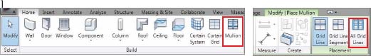
- Select the Mullion tool from the Build panel. You'll be given three different options to place those mullions: You can place a mullion continuously along a grid line, a segment of a grid line, or even on all empty grids on a panel (including the boundary). Let's select the third option (Figure 3.31).
FIGURE 3.31 Selecting the Mullion tool
The default mullion is fine for this exercise, but note that there are several mullions in the default template. You can even create mullions with user-defined profiles.
- Hover over the curtain panel and left-click, and the mullion will be assigned to all empty grids.
- To modify an element in the curtain panel, hover over the location and press and release the Tab key (don't just hold the Tab key down). Doing so will sequentially select the mullion, the grid line, the nearest panel, or the entire curtain system.
- Selecting the grid line and temporary dimensions allows you to enter exact values (or even press and drag to move the grid), as shown in Figure 3.32.
FIGURE 3.32 Moving the grid line
CURVED CURTAIN PANELS
Curved curtain wall panels that you create will appear “flat” until you add the vertical grid lines. But specifying exact grid locations during the design process is often tedious—and difficult to correct. You can create a “design” panel from a specially created wall that is very thin and transparent. Use this wall to figure out the design, and then swap it out for a curtain wall later. The wall can even have a pattern file associated to it that will visually help it to read as a curtain panel. Don't worry—we'll put a sample in the file that will be available at the end of the chapter.
Embedding Curtain Walls
Curtain walls can also be embedded in walls. Follow these steps:
- Create a 40′-0″ section (12 meters) of a Generic 6″ Wall.
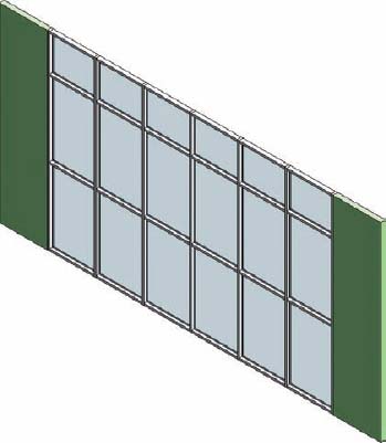
- Sketch a 30′-0″ (9 meters) section of a Storefront type curtain wall inside the wall. This curtain wall type has grid and mullion definitions as part of the wall (see Figure 3.33).
As you can see, the curtain wall will automatically imbed itself in the generic wall.
FIGURE 3.33 Embedding curtain walls
Modifying Curtain Walls
It's very seldom that our design ends up exactly where we started. So let's experiment with modifying our embedded curtain wall. This is a very important step not only in grasping how certain functionality works in Revit, but also in understanding the flexibility in your workflow and how Revit will accommodate it.
Editing the Elevation Profile
Complete the following steps to modify the elevation profile of a curtain system—even one embedded in a wall:
- Select the entire system by hovering over the outer edge of the curtain panel and selecting it. Now you can modify the elevation profile.
- Click Edit Profile and modify the sketch of the curtain wall as shown in Figure 3.34.
FIGURE 3.34 Modifying the sketch lines
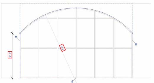
- Trim the side sketch lines and delete the top sketch line before finishing the sketch. Then click OK.
- When you attempt to finish the sketch, Revit will warn you that some of the mullions in the original system can't be maintained. This is fine, because some of the mullions are outside the sketch area. Click Delete Elements to continue.
Revit has already “healed” the outer generic wall to match the new boundary condition.
Adding and Modifying Grids and Mullions
![]() Now let's add some additional grids that are not part of this defined system:
Now let's add some additional grids that are not part of this defined system:
- First, select the grid tool and hover over the curtain system, as shown in Figure 3.35.
FIGURE 3.35 Adding a new grid and mullion
- When the grid line is evenly spaced between the upper and lower mullions, place the new grid line, which will resemble the one in Figure 3.35.
Because this type of curtain system already has a defined mullion, Revit will automatically add the mullion when you place the grid line.
Unpinning and Toggling Mullions
Now we need to exchange a door for one of the panels. Let's start by deleting one of the added mullions:
- Zoom into the curtain system and hover over the mullion. When it highlights, select the mullion.
- Notice the “pin” icon just above the mullion in Figure 3.36. The mullion is “pinned” because it's part of a defined system (in the type properties of the curtain panel).
- You need to “unpin” the mullion before you can delete it. Select the pin icon and it will “unlock.”
- Now unpin and delete the mullion below the previous one. This gives you room for our curtain wall door.
FIGURE 3.36 Unpinning the mullion
Adding and Modifying Panels
Before you swap out the panel for a door, you need to “weld” these two panels into a single panel. Follow these steps:
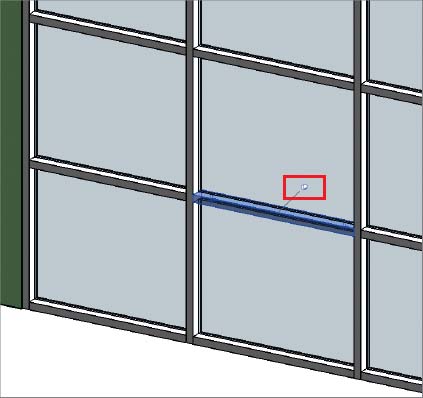
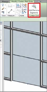
- Hover over the intersection of the two panels and select the grid line shown in Figure 3.37.
- Click Add/Remove Segments and then select the grid line that separates the two curtain panels.
Now you have a single panel rather than two panels, because the two panels have been welded together.
You can swap out the single panel with another panel; when you do so, the entire element is replaced. If you had not welded these two panels together, only the upper or lower panel would have been replaced individually.
Adding and Modifying the Curtain Panel Door
Before you swap out the glazed panel for curtain wall doors, let's load the appropriate family into the project. There's little point in getting ready to exchange the panel if you don't have the new panel ready to go!
- From the Insert tab, select the Load Family option on the Load From Library palette. From the Doors folder, select the Curtain Wall Dbl Glass family. The family is now loaded into our project and you can exchange it for the default curtain panel.
- You'll exchange the panel by first selecting the panel that you want to replace. Right away, you can see that the panel is also “pinned” since it's being defined by the type properties for the curtain wall system— just like the mullions. As you'll recall, pinned elements can't be exchanged until they're unpinned. The same holds true for this panel.
- Select the panel and unpin the panel. Now you can select a new option from the Properties pallet and replace the panel with a door, as shown in Figure 3.38.
FIGURE 3.38 Exchanging the panel for a door
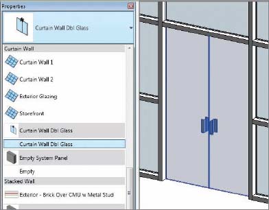
The curtain panel doors automatically expand to fill the space of the entire panel that preceded it. These are special doors that are really a curtain panel category. If you want a “real” door, you can swap out the curtain panel for a wall (even a wall made only of glass), and then place the door in the wall.
Understanding Basic Wall Parts and Parameters
Without going into too much detail, let's take a moment and discuss some of the various wall types that are available in Revit. We don't think it would be a good idea to have you make all of these now. But it's good to know what is in the box so that as your design progresses you won't get the sense that you'll be backed into a corner. The idea is that once you get the basics down, you'll want to begin experimenting with more complex wall types.
There are basically three types of walls in Revit: basic, stacked, and curtain walls. Let's discuss each of these types in a bit more detail.
Basic Walls
Many basic walls have no defined vertical information. They'll be monolithic—like the generic wall type that we've been using for most of these exercises. But in some cases they'll be specific types of monolithic walls. In these cases, the structural region is defined.
Select the Generic – 8″ Masonry wall type and then open the wall's type properties. Click Preview and select the Section view type. In Figure 3.39, the structural region of this wall is defined by a diagonal crosshatch pattern. This is a basic wall with only one pattern defining the wall's material.
FIGURE 3.39 Masonry structural region

However, basic walls may show far more vertical information and detail. Select the wall type Exterior - Brick on Mtl. Stud and you'll see the difference (Figure 3.40). Notice that there are numerous values that control the function, material, and thickness for this wall type. These values help you coordinate your project information across views and schedules. If the wall you select is right anywhere, it's right everywhere!
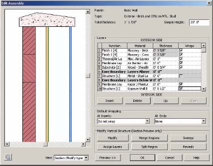
Basic walls can even have profiles associated to them. Profiles can be used to add or remove geometry in your walls. Take a look at the wall type Exterior - Brick and CMU on MTL. Stud. Note the parapet cap at the top of the wall (Figure 3.41). This is a profile associated to the basic wall type. So while you can manually add profiles to walls in your project on a case-by-case basis, we think you'll find adding them to the wall definition makes creating and updating wall types easy and quick.![]()
FIGURE 3.40 Vertically compound walls
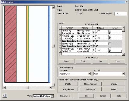
FIGURE 3.41 Wall sweep as part of a wall
Stacked Walls
![]() So what are stacked walls? They're your basic wall types, but in a single defined type. So any of your basic walls can be used to create a stacked wall.
So what are stacked walls? They're your basic wall types, but in a single defined type. So any of your basic walls can be used to create a stacked wall.
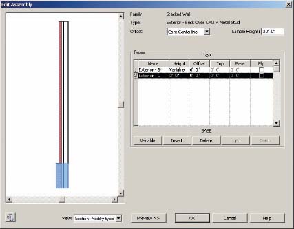
Look at the wall type Exterior - Brick Over CMU w Metal Stud, shown in Figure 3.42. It's defined by two different basic walls, but you can add more. However, you can't combine stacked walls (talk about confusing!) or curtain walls into your stacked wall.
FIGURE 3.42 Stacked wall section
Curtain Wall Types
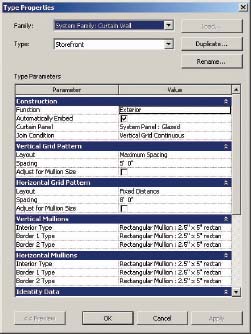
Curtain walls can have complete type definitions (Figure 3.43). The definition will include the mullion type (horizontal and vertical) for the interior and border conditions. But you can also control the horizontal and vertical spacing in the type definition as a type, which is very handy. But what's really cool is that you can also assign panel types to the curtain system type.
FIGURE 3.43 Curtain wall type definitions
Just One More Thing
Walls and curtain walls can be far more complex than the examples you've created in this chapter. If you want to examine all the types, go to the Chapter 3 folder at this book's web page at www.sybex.com/go/revit2012essentials and download 03_Walls_and_Curtainwalls.rvt.
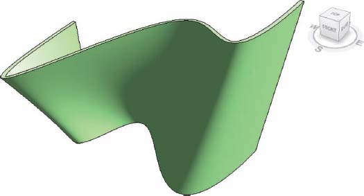
First, there's the option to create walls by picking a face (Figure 3.44). Essentially you create a mass and then assign walls to the face of the mass. If the mass is modified, you can reassign walls to the modified faces. As you can see in Figure 3.44, the results can be complex.
FIGURE 3.44 Walls created by picking a face
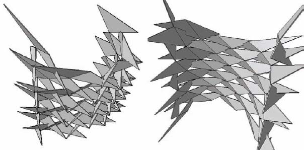
Not only can you create walls in this manner, you can also create complex curtain systems. These mass-based curtain types can contain very complex panel configurations. In some cases, the results may not even resemble a typical glazed system (Figure 3.45).
Once again, the important thing is to understand the basics. Resolve your design intent. Don't get hung up on modeling in Revit when you can sketch. Get feedback from someone who's a Revit expert and is willing to share.
FIGURE 3.45 Curtain panel system
THE ESSENTIALS AND BEYOND
Creating complex wall conditions is possible but takes time and patience. In more complex conditions, walls can also be embedded into other walls. But for an essential understanding of Revit, this is a great start; you've created walls of many types, added hosted elements—and even edited their profiles.
ADDITIONAL EXERCISES
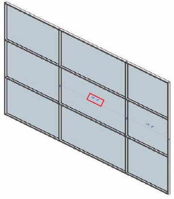
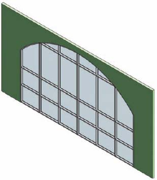
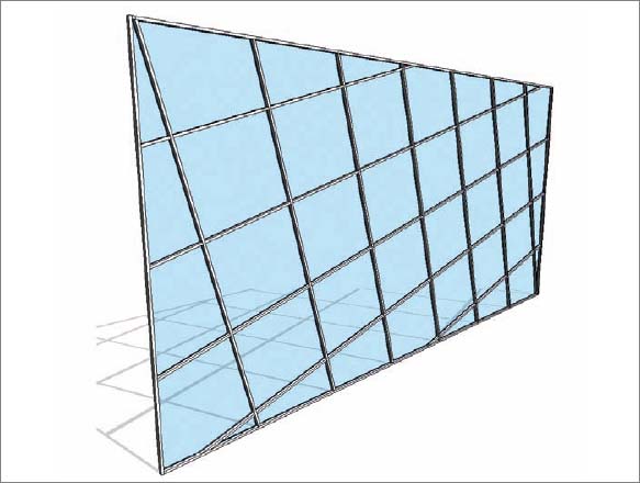
Create the following curtain wall condition. Note that the mullions are angled. You'll need to modify the Type, Instance, and Grid Layout properties to come up with the most flexible solution.
The curved wall in the next graphic has a complex star-shaped opening that is being filled by another curved wall that is star shaped (and fits exactly inside that opening). You can't create non-rectilinear openings in curved walls with the Wall Opening tool. You'll need to use an in-place family.
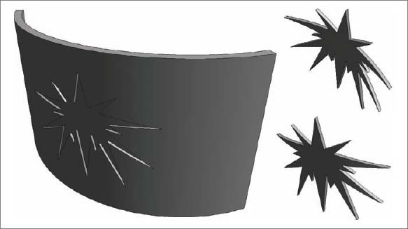
If you get stuck, both of these walls are in this chapter's sample Revit project at the book's web page.