
CHAPTER 12
Creating Drawing Sets
While the industry continues to move toward a 3D BIM model as a construction deliverable, today we still need to produce 2D documents for a construction set. Fortunately because of Revit, we can create these sets with more accuracy and dependability than in the past. In this chapter, you will work on taking the elements and creating documentation.
In this chapter, we're going to introduce a scenario that will mimic what might happen on a real project in preliminary design. You'll be using the Residence.rvt model from the book's web page (www.sybex.com/go/revit2012essentials) in the Chapter 12 folder.
Here's the story: You have recently completed some design work in advance of your upcoming pricing package for a residential design project. You will need to lay the plans, elevations, and perspectives out on some sheets for the package. But you want to help the contractor with some quantities, so you also want to include some schedules. With this scenario in mind, you need to lay out the views already created onto sheets, create some schedules, and then get the drawing set printed.
In this chapter, you learn the following skills:
- Creating schedules
- Placing views on sheets
- Printing documents
Creating Schedules
Schedules are lists and quantities of elements and element properties within the model. They itemize objects, including building families such as walls, doors, and windows; calculate quantities, areas, and volumes; and quantify elements such as the number of sheets, keynotes, and so on. They are another way to view a Revit model. Once created, they are dynamically kept up-to-date with any changes that occur to the model itself.
Understanding Schedules
![]() In a project workflow, creating schedules of objects, areas, or quantities is usually one of the most laborious tasks for architects. When this process is performed manually, it can take a very long time and typically results in errors requiring much checking and rechecking of the information. In Revit, all the elements have information about their properties defined within the model. You also have the option to add information or categories to any existing element. For example, in Revit, doors have properties such as size, material, fire rating, and cost. All of this information can be scheduled and quantified. As those doors are changed within Revit, the properties update in the schedule.
In a project workflow, creating schedules of objects, areas, or quantities is usually one of the most laborious tasks for architects. When this process is performed manually, it can take a very long time and typically results in errors requiring much checking and rechecking of the information. In Revit, all the elements have information about their properties defined within the model. You also have the option to add information or categories to any existing element. For example, in Revit, doors have properties such as size, material, fire rating, and cost. All of this information can be scheduled and quantified. As those doors are changed within Revit, the properties update in the schedule.
Revit lets you schedule elements based on the element's properties. This means that almost anything placed in a Revit model can be scheduled and quantified. Because the schedule is simply viewing the elements within the model in a nongraphical way, making change to the elements in a schedule view makes changes to the element in the model, and vice versa.
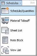
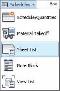
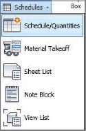 Revit has several types of schedules. They can all be accessed from the Create panel of the View tab. The Schedule flyout is shown in the margin. There are five primary types of schedules you can create using Revit. Let's look at each:
Schedule/Quantity This is the most commonly used schedule type in Revit. This schedule allows you to list and quantify all the element category types in Revit. You would use this type to make door schedules, wall schedules, window schedules, and so on. These schedule types are limited to scheduling properties within the same category.
Material Takeoff This type of schedule lists all the materials and subcomponents of any Revit family category. You can use a material takeoff to schedule any material that is placed in a component or assembly. For example, you might want to know the cubic yardage of concrete within the model. Regardless of whether the concrete is in a wall or floor or column, you can tell the schedule to report the total amount of that material in the project. Material takeoffs will report material properties across multiple categories.
Sheet List This schedule allows you to create a list of all the sheets in the project.
Note Block This schedule lists the notes that are applied to elements and assemblies in your project. You can also use a note block to list the annotation symbols (centerlines, north arrows) used in a project.
View List This schedule shows a list of all the views in the Project Browser and their properties.
Each of these schedule types has a host of categories that you can mix and match to make schedules and track elements within the model. All of these schedules are broken down into some common elements that allow you to build and customize your schedules. Let's step through these elements and see how they can be used.
To begin a schedule, select Schedule/Quantity since it is the most widely used of schedule types. Selecting any of these schedule types will give you the New Schedule dialog box (Figure 12.1).
FIGURE 12.1 Creating a new schedule
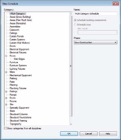
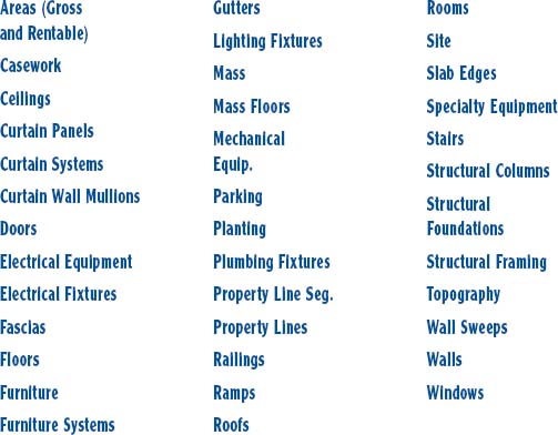
This dialog box allows you to choose the category you would like to schedule. As you move through the list on the left, you can see a host of different schedule categories, as listed here:
If there aren't enough categories for you to choose from to create customized schedules, Revit provides a venue to add additional options. At the bottom-left corner of the New Schedule dialog box is the Show Categories From All Disciplines check box. Selecting this check box gives you the ability to schedule elements from MEP and Structural categories. This option can be useful when you have those disciplines supplying Revit files to you and you are linking them into your architectural model.
Revit also gives you the opportunity to create schedules that span categories. The first option in the dialog box in Figure 12.1 is the Multi-Category schedule. You might want to schedule all the casework and furnishings in a project simultaneously. Or perhaps you want to schedule all the windows and doors if they are being ordered from the same manufacturer. A Multi-Category schedule allows you to combine a number of categories into one schedule. One of the limits of this schedule type is that you cannot schedule host elements (walls, floors, ceilings, and so on) but only their materials and family components.
With this description in mind, let's look at the other options when creating a schedule. Choose Walls and click OK. Doing so opens a new dialog box called Schedule Properties. Here, you can set the various properties of a schedule that define not only how it looks, but what information it reports.
There are five tabs across the top: Fields, Filter, Sorting/Grouping, Formatting, and Appearance. Each of these controls different aspects of the schedule. Let's step through each of these tabs and see how they affect the look and reporting of the schedule:
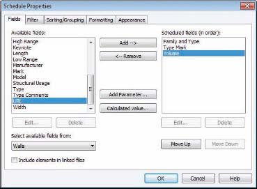
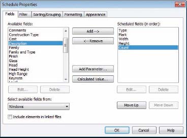
Fields The Fields tab (Figure 12.2) lets you select the data that will appear in your schedule. For the wall schedule, it shows all the properties available in the wall family (we chose Family And Type, Type Mark, and Volume). The list of available fields on the left will vary based on the family you chose to schedule. If you've added any project-based parameters to those family categories, they will be available here as well. Also notice at the lower-left corner is the option Include Elements In Linked Files. Enabling this option allows you to schedule across multiple files and can be a great tool on larger projects.
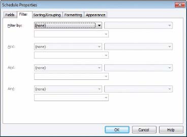
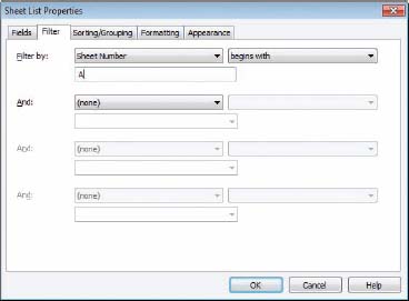
Filter On the Filter tab (Figure 12.3), you can filter out the data you don't wish to show in your schedule. Filters work like common database functions. For example, you can filter out all the sheets in a set that don't begin with the letter A. Or you can filter a material list so that it shows only items containing Concrete.
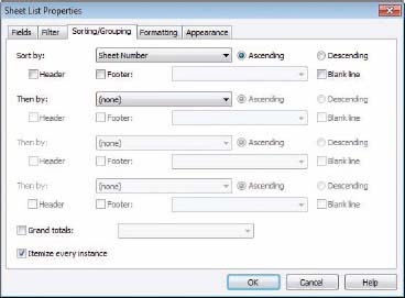
![]() Sorting/Grouping The Sorting/Grouping tab (Figure 12.4) lets you control the order in which information is displayed and which elements control that order. For instance, if you are creating a sheet index you can choose to sort by Sheet Number or Sheet Name, depending on how you'd like the information displayed. You can also decide whether you want to show every instance of an item or only the categories for a family by using the Itemize Every Instance check box at the bottom.
Sorting/Grouping The Sorting/Grouping tab (Figure 12.4) lets you control the order in which information is displayed and which elements control that order. For instance, if you are creating a sheet index you can choose to sort by Sheet Number or Sheet Name, depending on how you'd like the information displayed. You can also decide whether you want to show every instance of an item or only the categories for a family by using the Itemize Every Instance check box at the bottom.
FIGURE 12.4 The Sorting/Grouping tab

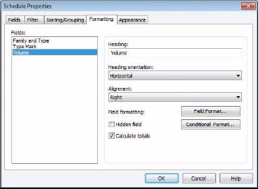
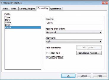
Formatting The Formatting tab (Figure 12.5) controls the display heading for each field and whether the field is visible on the schedule. It also controls other elements of the field, such as justification, display name, and orientation of the header. This tab also allows you to use the Calculate Totals check box. Not all Revit fields will calculate their total values at the bottom of the schedule. By highlighting the field on the left, you can check the Calculate Totals box and show a sum at the bottom for any numerical column.
FIGURE 12.5 The Formatting tab
Appearance The Appearance tab (Figure 12.6) controls the graphical aspects of the schedule, such as font size and style of text for each of the columns and headers in the schedule. It also allows you to turn the schedule grid lines on and off, as well as modify the line thickness for the grid and boundary lines.
FIGURE 12.6 The Appearance tab

Once you've established the fields and look of your schedule, clicking OK gives you a preliminary layout. This layout can be modified at any time during the project, but it gives you a basis from which to begin. To modify the schedule at any time, simply click the Element Properties button or right-click and choose Element Properties from the context menu.
Schedules have their own special tab on the ribbon that is active when you are viewing the schedule outside of a sheet. The tab (Figure 12.7) allows you to select the properties, add and delete rows, and show or hide columns within the schedule.
FIGURE 12.7 The Schedule tab buttons
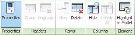
Another key feature of this menu bar is Highlight In Model. This button allows you to select any element in the schedule from any cell and locate that element in the model. Let's say you want to locate a particular door from your door schedule. Highlight the door in the schedule and click the Highlight In Model button, and Revit will take you to a different view with that door highlighted. This feature can be a useful way to locate elements in the model, especially for larger models.
Now that you have an idea of the elements that compose a schedule, let's return to our demonstration workflow and create a Rentable Area schedule based on the areas we've defined earlier in this chapter.
Making Schedules
 Now that we've discussed some of the features of the Schedule tool, let's open the Residence.rvt model and make a couple of schedules. When you first open the model, you'll notice that there are several views and sheets already created. This model is a work in progress—it's a private residence of 1,230 square feet. The project is a renovation of a 1890s two-story brick. In the design, all the interior walls have been eliminated and put on a “demo” phase, which keeps the 19′ clear span as open as possible. All new interior walls have been added and the entire interior refreshed within the historic shell. Since the renovation is so substantial, the designer chose to replace all the existing original windows with new insulated, wood windows. To assist the window manufacturer with the custom sizes, you need to create a window schedule. To begin, choose the Schedule/Quantity button from the Schedule drop-down menu on the View tab.
The New Schedule dialog box (shown earlier in Figure 12.1) opens. Here you'll make a series of selections to create the schedule. Follow these steps:
- From the Categories list, select Window at the bottom. Since this project has multiple phases, you want to make sure the phase is set to New Construction—you don't need to schedule the windows you're removing. Click OK when you've finished.
- We're now going to step through the five tabs in the Schedule Properties dialog box. This will help you format the schedule and choose what you'd like to see. Starting with the Fields tab, choose the following fields:
Type This represents the family type or, in our case, the window name.
Type Mark This is the letter that you'll use on the elevations to define the window type in your document.
Width Specify the window width.
Height Specify the window height.
Count Specify the number of times a window type appears in the model.
Choose these fields from the Fields list on the left and, using the Add button, move them to the right (Figure 12.8). You can use the Move Up or Move Down button to change the order of the fields.
FIGURE 12.8 Adding fields to our Window schedule
- Choose the Sorting/Grouping tab. From the Sort By drop-down, choose Type.
- In our schedule, you want to make the window count read as it would in a spreadsheet: right-justified. Choose the Formatting tab and select Count from the list on the left. Change the Alignment setting to Right (Figure 12.9). In the same way, you can choose the Type Mark field and choose to center-justify it so all the letters will align nicely.
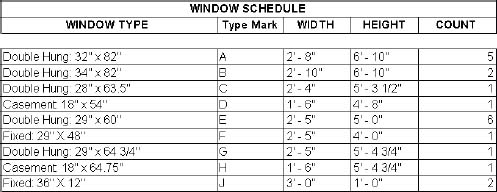
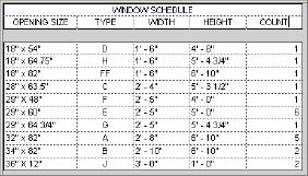
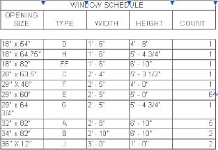
- We're going to leave the rest of the schedule at the defaults, so click OK. Revit will follow the directions you have given it to display the schedule that appears in Figure 12.10. Note that you can also change any of the heading names by simply typing inside the box. Since Type Mark isn't a value that most people relate to, we've simplified it to Type and made the rest of the field names all uppercase.
FIGURE 12.10 The Window schedule
Following these simple guidelines, you can create all kinds of schedules in your project.
Creating a Room Schedule
Creating other schedule types is fairly simple if you follow the guidelines we just went over and step through the tabs in the Schedule Properties dialog box. Since you have one schedule under your belt, let's try another one—this time, you'll create a room schedule. To do this, begin by choosing the Schedule/Quantity button from the Schedule drop-down on the View tab, and then follow these steps:
- Choose Rooms from the New Schedule dialog box and click OK.
- Choose the following fields from the Schedule Properties dialog box:
- Number
- Name
- Floor Finish
- North Wall
- East Wall
- South Wall
- West Wall
- Area
- Comments
When you're done, click OK.
- On the Sorting tab, choose Number.
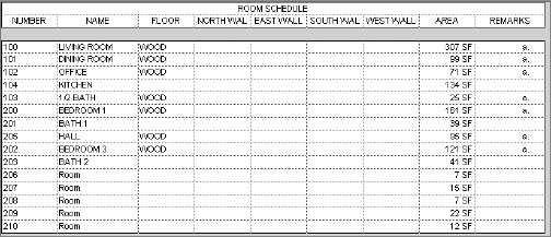
- On the Formatting tab, choose Area and justify to the right. Click OK to get the schedule you see in Figure 12.11.
FIGURE 12.11 Our Room schedule
Now, let's do something slightly different with this schedule. Since four of our columns are dealing with wall finishes, let's add a header to those columns so you can group them under one header, Wall Finishes. To do so, start by selecting the four headers as shown in Figure 12.12. Grab one with your mouse and holding down the left mouse button, drag across to select all four.
FIGURE 12.12 Selecting the wall finishes
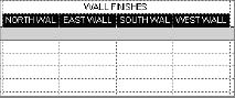
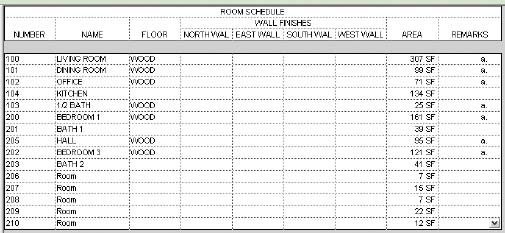
 With the four columns selected, choose the Group button from the Headers panel. This will give you a new row above your existing headers. Now you can type Wall Finishes to complete your schedule (Figure 12.13).
FIGURE 12.13 The Room schedule
 Once this schedule is complete, you'll notice that some of the fields already have data in them. This is due to the fact that some of this information is generated automatically by Revit (like room areas) and some of it was added earlier in this process by adding room numbers to the plans or room names. Remember, schedules are just a nongraphical way of viewing the model—changes to the schedule will alter what you see in the model.
Creating a Sheet List
Sheet List is a different schedule type that you can create in Revit. The Sheet List schedule allows you to create a list of sheets in your project that are found within the Project Browser. This can be handy, especially on larger projects where the sheet list can tend to get long. This tool is also located in the Schedules flyout on the View tab.
This schedule has a feature that allows you to create placeholders for sheets that are not yet created or will not be a part of your discipline's drawings. You can use this feature to create full sheet schedules including all consultant drawings. It also allows you to create placeholder entries in the sheet schedule before you've created the sheets.
In our sample workflow, you have created several drawings and sheets, and you want to schedule them so you can add a sheet list to your drawings. To do so, begin by selecting the Sheet List tool from the Schedules flyout.
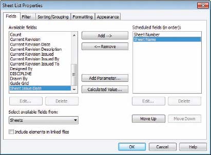
- You'll see the now familiar Revit schedule dialog box starting with the Fields tab. From this tab, you need to select two fields from the categories on the left and move them to the column on the right. Select the Sheet Number and Sheet Name categories (Figure 12.14).
FIGURE 12.14 Creating the sheet list
- On the Sorting/Grouping tab, choose to sort by Sheet Number and make sure the Itemize Every Instance check box is checked (Figure 12.15).
- Now, choose the Filter tab. You'll be creating a sheet index for your presentation sheets, so you don't want to include all the sheets in the set. You already have some of the construction documentation sheets in the file (the A series sheets), and you don't want those reported in your schedule. You want to filter out all the sheets that don't begin with the letter K (for the Kitchen sheets in this set).
- On the Filter tab, choose to filter by Sheet Number.
- From the next drop-down, choose Begins With.
- In the third field, enter the letter A. The filter should look like Figure 12.16.
- Be sure to use an uppercase A, as the Boolean queries in Revit are case sensitive. When you're done, click OK.
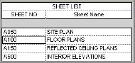
What you should have is a schedule with nothing in it but sheet numbers that begin with the letter A. Now you need to populate the rest of the sheet list.

 To begin adding sheets to the sheet list, select the New Sheet button from the Create panel. This will give you a row with a blank for both of your headings, Sheet Number and Sheet Name.
- To your sheet list, you'll add one of the two sheets you need for this set. You need a Plan sheet – A100. Clicking the New Sheet button will give you the New Sheet dialog box so you can add a sheet to the set (Figure 12.17).
FIGURE 12.16 Filtering out sheets
FIGURE 12.17 Adding sheets to the list
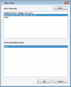
- Choose the 22×34 Sheet CD – C1 sheet and click OK. This will add a sheet to your project browser. By default, the sheets are added in sequential order, so whichever sheet was added the most recently will be the next sheet in the list. In this example, it will appear as A051, right after the A050 sheet. Right-click the sheet and choose Rename from the context menu. Rename the sheet to A100 – Floor Plans. You'll see a blank sheet in your view window. Closing this view will take you back to the schedule view with your new sheet in the list (Figure 12.18).
FIGURE 12.18 Adding sheets to the set
Placing Views on Sheets
Throughout this book, you have created several different kinds of views, from plans to elevations to perspectives. Eventually, you will need to lay out those views onto sheets so they can be printed or converted to PDF format and sent to clients or team members for review.
Creating sheets in Revit is very easy. As you've already seen, they can be created through a Sheet List schedule. You can also create sheets by right-clicking the Sheet node in the Project Browser and selecting New Sheet from the context menu. Regardless of which method you use to create them, let's walk through laying these views out on sheets and see how each view can be further manipulated once it's placed on a sheet.
Adding Floor Plans to the Sheet
![]() Since you have already created a series of views, let's use the sheet you've just made for this purpose. Open the A100 – Floor Plans sheet in the view window by double-clicking it in the Project Browser. Now, let's add our first view: the Basement floor plan. To begin, drag and drop the plan from the Project Browser and onto the sheet. The view will show at the proper scale and with a View Title already established. You can then drag the view across the sheet to place it where you'd like to have it (place it on the left side—you'll add more). Figure 12.19 shows the view placed on the sheet.
Since you have already created a series of views, let's use the sheet you've just made for this purpose. Open the A100 – Floor Plans sheet in the view window by double-clicking it in the Project Browser. Now, let's add our first view: the Basement floor plan. To begin, drag and drop the plan from the Project Browser and onto the sheet. The view will show at the proper scale and with a View Title already established. You can then drag the view across the sheet to place it where you'd like to have it (place it on the left side—you'll add more). Figure 12.19 shows the view placed on the sheet.
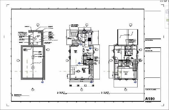
Now, since we have a bit more space left on the sheet, let's add a couple of other views. Add Level 1 and Level 2 by dragging and dropping them from the Project Browser and on to the sheet. You should notice when you're placing your second and third views on the sheet that you will be presented with an outline of the plan view with a dashed line in the center of the view. This is an alignment tool; Revit is assuming that you want the plans to align on the sheet and it is intelligent enough to aid you in this process. You can casually drag the views around on the sheets enough to find the alignment lines and to ensure that all your plans will line up (Figure 12.20). Your sheet full of views should look like Figure 12.21.
FIGURE 12.19 Placing the view on a sheet

FIGURE 12.20 Aligning views on sheets
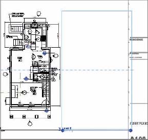
FIGURE 12.21 All the views placed on the sheet
![]() Once the views are placed on a sheet, there will inevitably be a bit of cleanup you'll want to do to the drawings to get everything placed properly and looking good. First of all, by default, Revit will place the View tag in roughly the same place for each view, and that might not be the location you ultimately want it to be in. Revit will also number the views sequentially (1, 2, 3, ...) in order of placement.
Once the views are placed on a sheet, there will inevitably be a bit of cleanup you'll want to do to the drawings to get everything placed properly and looking good. First of all, by default, Revit will place the View tag in roughly the same place for each view, and that might not be the location you ultimately want it to be in. Revit will also number the views sequentially (1, 2, 3, ...) in order of placement.
![]()
Let's adjust the view tags a bit on the sheets. To adjust the text in the tags, start by selecting the view itself—not the tag. To adjust the tag location, you'll want to select the tag itself.
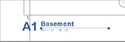
- Start by selecting the view for the Basement. The tag will highlight in blue. You want to change two things on the tag: the number and the length of the line.
- Select the number 1 and change it to A1 to reference the ConDoc drawing system—letters vertically along the side of the sheet and numbers across the bottom of the sheet. Move the detail to the location on the lower-left corner of the detail on the drawing sheet.
- Next, using the blue grips on the view tag line, drag the right grip closer to the end of the Basement text. Your tag will look like Figure 12.22.
FIGURE 12.22 The edited view tag
- Now, clearly you can't leave the view tag there as it's falling off the left edge of the sheet—you need to move it to a better position. Click off the tag, anywhere in the view, to deselect the tag. You can also press the Esc key twice or select the Modify arrow at the upper left. Then, select the tag itself. It will highlight blue again, but without the grips on the line. Now, you can click and drag the tag to any location on the sheet (Figure 12.23).
FIGURE 12.23 Moving the view tag

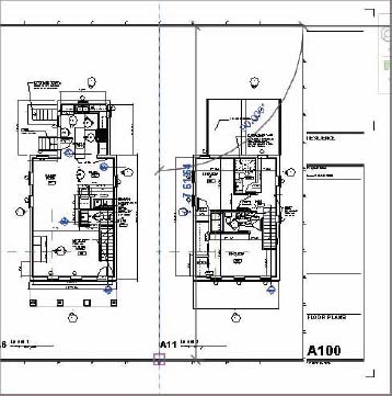
- Do the same to the other two views. Rename Level 1 to A6 and Level 2 to A11 to match their location on the sheet as shown, shortening the view tag lines to a more appropriate length (Figure 12.24).
FIGURE 12.24 Laying out the rest of the sheet views

To finish organizing your sheet, you want to add a few lines to divide the different views. You can do so easily by using the Detail Line tool ![]() , which can be found on the Annotate tab.
, which can be found on the Annotate tab.
- Choose Detail Line from the Detail Panel.
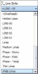
- Doing so activates the Modify | Place Detail Lines context menu. From the Line Style panel on the far right, choose Wide Lines from the drop-down.
 Once the desired line style is selected, you're ready to start drawing lines. By default, the straight line tool is active, and you can select one of the nodes on the sheet between views and draw a vertical line between the Basement and Level 1 and between Level 1 and Level 2 (Figure 12.25).
FIGURE 12.25 Adding lines to the sheet
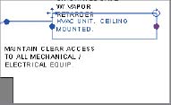
With these dividing lines in place, you notice that one of your annotations in the Basement view is a little too close to the drafting line (Figure 12.26). You want to adjust it.
To do this, you could simply open the view and adjust the text box, but you wouldn't have the sheet as a reference. Instead, you're going to use a command called Activate View.
FIGURE 12.26 Adjusting text in the sheet view

Activating a view is like working in model space through paperspace in CAD. You're working on the actual view but you're doing so while it is placed on the sheet. This approach allows you the benefit of seeing how changes to the view will affect the layout of the view on the sheet.
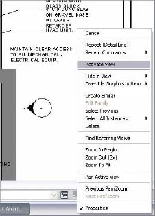
- To begin, right-click the view and choose Activate View from the context menu (Figure 12.27).
FIGURE 12.27 Activating the view
- With the view activated, you'll notice that the other views have become grayed out. Revit is showing you only the elements you can currently edit—those within the view. Select the text box that you've identified and, using the grips, drag the right grip inward so the text wraps (Figure 12.28).
FIGURE 12.28 Modifying the text box
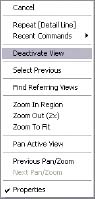
- To complete your edits, you now need to deactivate the view. Right-click anywhere outside the view and choose Deactivate View from the context menu (Figure 12.29).
FIGURE 12.29 Deactivating the view
Adding the Schedules
With your A100 sheet laid out and ready to print, you can quickly finish your sheet set by adding the Window schedule you created earlier. Adding a schedule is just like adding any other view—you simply drag and drop it from the Project Browser onto the sheet.
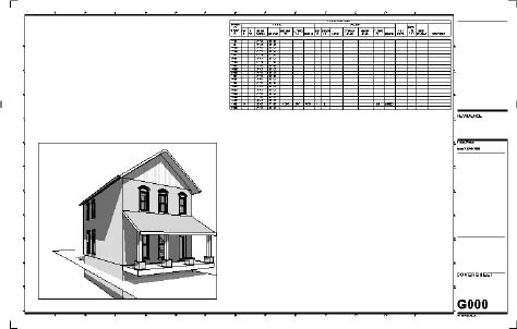
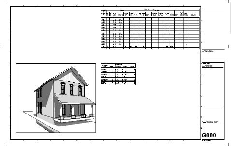
- Open sheet G000 Cover Sheet by double-clicking it in the Project Browser (Figure 12.30).
- Grab the Window schedule from the Project Browser and drag and drop it into the open area on the sheet.
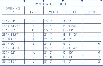
With the schedule on the sheet, it looks like it needs a bit of adjustment. You can redefine the column spacing so you can make any visual adjustments to the schedule while it is on the sheet to help it read better. Such adjustments do not change the actual schedule but just its appearance on the sheet itself.
To do so, highlight the schedule by selecting it. The schedule will turn blue and you'll have a few new grips to help you make changes (Figure 12.31). The blue inverted triangles at the top of each column allow you to modify the column widths. Grab one and drag it left or right to change the column sizing.
FIGURE 12.31 Modifying the schedule on the sheet
You'll also notice a blue cut symbol ![]() . This cut symbol allows you to break the schedule into parts while on the same sheet. This can be especially handy if you have a long schedule like a room or door schedule and it has too many rows to fit on your sheet vertically. Selecting this tool breaks the schedule in half (and you can break it into half again and again) so that you can take advantage of the horizontal real estate on your sheet. If you choose to separate your schedule in this fashion, it still retains all the necessary information and all the portions continue to automatically fill themselves out dynamically as a single schedule would. You also have the opportunity to change the overall height of the schedule once it is broken up by grabbing the grips at the bottom of the schedule and dragging up and down.
. This cut symbol allows you to break the schedule into parts while on the same sheet. This can be especially handy if you have a long schedule like a room or door schedule and it has too many rows to fit on your sheet vertically. Selecting this tool breaks the schedule in half (and you can break it into half again and again) so that you can take advantage of the horizontal real estate on your sheet. If you choose to separate your schedule in this fashion, it still retains all the necessary information and all the portions continue to automatically fill themselves out dynamically as a single schedule would. You also have the opportunity to change the overall height of the schedule once it is broken up by grabbing the grips at the bottom of the schedule and dragging up and down.
With your schedule on the sheet and the columns properly formatted, you can drag the schedule around on the sheet until it's located where you'd like to have it. To move it around, click and hold the left mouse button down on the schedule. As you move it around on the sheet, you'll notice that like other views in Revit, the schedule will justify with the other schedules on the sheet and give you a light green dashed line to help align the two. Your finished sheet will look like Figure 12.32.
FIGURE 12.32 The finished sheet G000
Printing Documents
With all of your documents and sheets laid out, you will eventually need to get the sheets out of Revit and into a printed format. If you've been working in the Windows environment, you'll find that printing from Revit is straightforward, because it's similar to other Windows-based applications.
The Print Dialog Box
To print, you do not need to be in any particular view or sheet. Select the Application menu and choose Print ![]() Print to open the dialog box shown in Figure 12.33. All the features for printing are found here. Let's step through this dialog box and explore each element.
Print to open the dialog box shown in Figure 12.33. All the features for printing are found here. Let's step through this dialog box and explore each element.
The drop-down menu at the top of this dialog box allows you to select the printer or plotter you wish to print to. This can be a physical printer or a virtual one (like Adobe Acrobat Distiller). You add printers to this list using your Windows Printer control panel. Most of the controls you need to use can be found at the bottom of this dialog box in the Settings section on the right and the Print Range on the left.
Print Settings
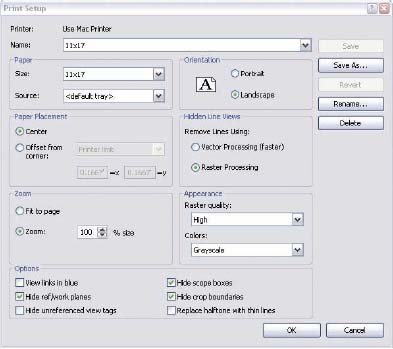
The printing environment is set up using the Print Setup dialog box (Figure 12.34). Here you set up a printer and settings for printing. You can save these settings with a name so that you can reuse them in later Revit sessions. These settings can also be transferred to other Revit projects if need be, using the Transfer Project Standards tool located on the Manage tab. Let's take a look at some of the printing options available to you.
Hidden Lines Views
Views in Revit can be displayed in four graphic modes: Wireframe, Hidden Line, Shaded, and Shaded With Edges. The most commonly used type is Hidden Line. You'll choose this type for floor plans, sections, and elevations, and sometimes even for 3D.
Revit lets you select whether you wish to print this type of view with vector processing or raster processing of the hidden lines. Vector is faster; however, you need to be aware of some nuances when working with hidden line views. For example, transparent materials (like glass) print transparent with raster processing but opaque with vector processing.
FIGURE 12.34 The Print Setup dialog box

Options
The Options pane is at the lower left in the Print Setup dialog box. The pane includes these options:
View Links In Blue View links are hyperlinked tags that lead you from one view to another or from a sheet to a view. They appear blue in Revit and print black by default, but you can specify to print them in blue, which is how they appear on the screen.
Hide Ref/Work Planes; Hide Scope Boxes; Hide Crop Boundaries These three check boxes let you decide whether to print various Revit-specific graphics, including reference planes, scope boxes, and crop boundaries.
Hide Unreferenced View Tags During the course of a project, you may create a lot of elevation tags, section flags, or detail callouts for working purposes that you don't wish to be printed in the final documents or placed on any sheet. These view tags are referred to as unreferenced, and Revit gives you the option to not print them.
Once all of your options are set, you have the ability to save the settings so you can quickly reuse them on future prints. Choose the Save As button on the right, name the setting 11×17, and click OK. Now, click OK to close this dialog box. This will take you back to the Print dialog box.
Print Range
The other important part of the Print dialog box is the Print Range. In this section, you can define exactly what areas, sheets, or views you want to print. It includes these options:
Current Window This option prints the full extent of the open view, regardless of what extents of that view are visible currently on your screen.
Visible Portion Of Current Window This option prints only what you see in the frame of the open window framed for the sheet size you've selected.
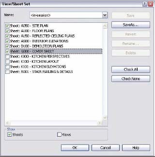
Selected Views/Sheets This option allows you to define a reusable list of views, sheets, or any combinations of views and sheets. This way, you can essentially batch-print a job by sending large quantities of sheets to the printer in one shot and save these selections for later print jobs.
This dialog box lets you pick any view or sheet to include in the View/Sheet Set. If you only want to include sheets in a set, use the Show options at the bottom of the dialog box to shorten the visible list. Doing so allows you to select only sheets or only views if you so choose.
This is a great tool to help define print lists. Some examples of what you might want to use these selections for would be a 100 percent construction document package or a specific set of presentation sheets.
- In our example, you want to print a set of sheets. Deselect the View check box at the bottom of this dialog box and Revit will display a list of the sheets you've created to date.
- Next, check the A series sheets, the D100 sheet, and the G000 sheet you just added the schedule to (Figure 12.35).
- Since you will more than likely want to print this set again, choose Save As from the menu on the right and name the set Set 1. This will keep your current collection of sheets together, and if you want to reprint this set, grab the set name from the drop-down menu. Remember, if you add more drawings to the set, by default they won't be added to this print set. You'll need to revisit this dialog box, add the sheets, and click the Save button. For now, click OK to close this dialog box.
- Our final dialog box looks like Figure 12.36. Clicking OK here will print the six selected drawings to the printer listed at the top. Clicking Close saves your print setup and closes the dialog box.
FIGURE 12.36 Finishing the prints
THE ESSENTIALS AND BEYOND
In this chapter, you learned how to quantify the elements in the model by using schedules. We used this same Schedule tool to create a standard door schedule and added a new schedule type for wall quantities. You also learned how to place all the views we've made over the course of the book onto sheets and print them. Finally, you learned how to combine these two techniques and schedule the sheets you created.
ADDITIONAL EXERCISES
- Create a door schedule adding the following fields:
Mark
Type
Width
Height
Thickness
Material
Finish
Comments
- Lay out this new schedule on sheet G000; be sure to align it with the schedule you already created on that sheet.