
CHAPTER 4
Floors, Roofs, and Ceilings
We've approached this chapter by grouping together horizontal host elements that make up your building. Although the initial creation of a floor, roof, or ceiling is somewhat different, the tools used to edit the initial design element have a lot of overlap and similarity.
In this chapter, you learn the following skills:
- Creating floors
- Laying out roofs
- Adding ceilings
Creating Floors
![]() There are quite a few ways to create floors in Revit. But we honestly don't have the space to dig deep into all these variations! Quite frankly they're not important for early design iteration.
There are quite a few ways to create floors in Revit. But we honestly don't have the space to dig deep into all these variations! Quite frankly they're not important for early design iteration.
What's important is that you understand what the various approaches to a single floor type will do and what kind of relationships they'll make. So let's get started!
Sketching
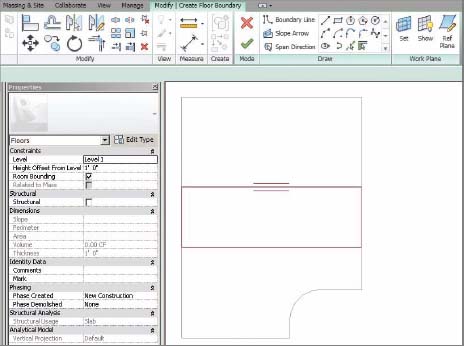
 First, let's create floors by sketching the desired shape in the Level 1 floor plan view. The floor type that we'll be using is Generic – 12″. Start by selecting the Floor tool on the Build panel of the Home tab. You'll enter Sketch mode, which will allow you to create a sketch that will eventually be used to define the boundary of your floor.
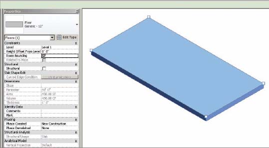
Let's create a simple sketch for the floor, 15′ × 30′ [4.5 m × 9 m]. The dimensions are shown for reference only. Even though this is a simple shape, what's more important is how you'll be able to manipulate the shape.
Finish the sketch and select your default 3D view. Now select the Floor tool and your floor will resemble the one in Figure 4.1.
Editing the Boundary
Note that you're able to see a couple of things right away in the instant properties: metadata about the floor (location, area, volume, etc.) as well as the ability to revise the geometry via sketching or spot elevations. Let's select Edit Boundary and return to the Level 1 floor plan.
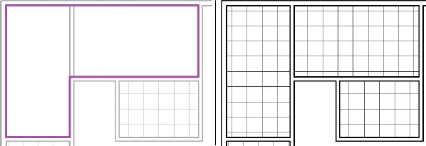
Add additional sketch lines to generate the shape at the bottom right of Figure 4.2. Don't forget to trim back any intersecting lines.
Once this is done and there are no overlapping lines, finish the sketch by clicking the green check button. Select the floor and you'll notice that the options and metadata have already updated, as shown in Figure 4.3.
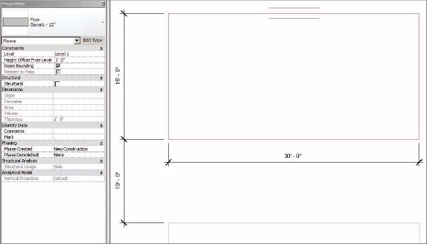
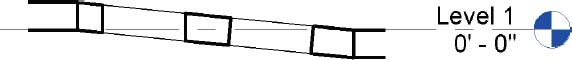
Now let's create another floor of the same type and same initial dimensions: 15′ × 30′ [4.5 m × 9 m], just above the first floor. Leave some space between the two floors. Offset the floor 1′-0″ [300 mm] above Level 1 by entering this distance into the Properties palette. Finish the sketch to complete the floor (Figure 4.4).
FIGURE 4.2 Modifying the floor sketch
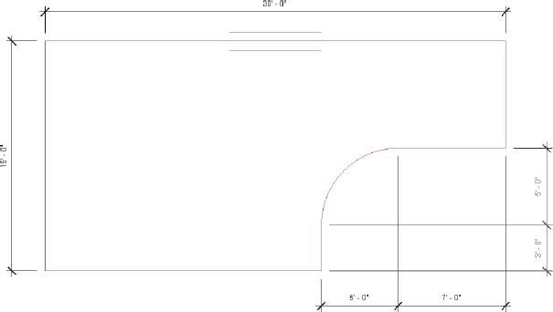
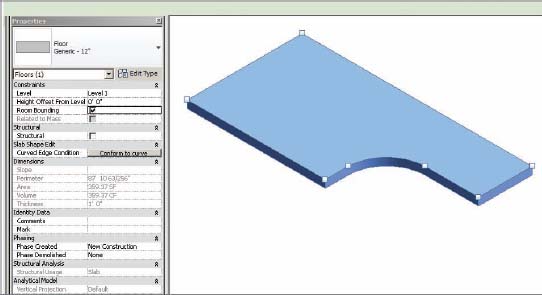
FIGURE 4.4 New floor 1′-0″ above Level 1
Sloped Arrows and Floors
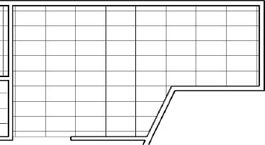
Not all floors are flat, and many have large openings. Let's investigate both options. We'll begin by bridging another sloped floor between the first two. Sketch another floor between the two previous floors, filling the gap between the two (Figure 4.5).
FIGURE 4.5 New floor at Level 1
If you were to finish the sketch like this, the floor wouldn't connect the upper and lower sections. You need to add a slope arrow. Do so by selecting the Slope Arrow tool on the Draw panel. Sketch the arrow as shown in Figure 4.6. The first location that you pick will be the tail of the arrow; the second location is the head.
FIGURE 4.6 Slope arrow constraints
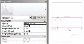
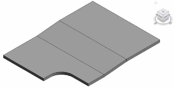
Once you create the slope arrow, select it and modify the parameters as shown in Figure 4.6 so that they match the location of the upper and lower floors. Be sure to specify the heights of the tail and head. Finish the sketch and return to your default 3D view (Figure 4.7), which shows the finished condition. Now the sloped floor connects the lower and upper floors.
FIGURE 4.7 Completed sloped floor
Sloped Floors via Shape Editing
Slightly sloped floors and depressions could be created with slope arrows and separate floors—but this approach is probably too complex since you'd have to create a lot of separate pieces of geometry. For these kinds of conditions, you have the Shape Editing tools.
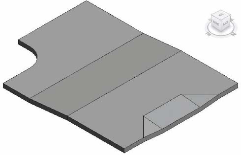
Let's start by returning to Level 1 and selecting the upper floor. Now you can see the Shape Editing tools in the Shape Editing panel. Let's suppose that this entire floor is at the right level, except for one small portion that needs to be slightly depressed in order to accommodate a loading area.
 First, let's define the upper and lower boundaries of this depressed area by selecting the Add Split Line option from the Shape Editing panel. Add the spline lines as shown in Figure 4.8. Dimensions are shown for reference.
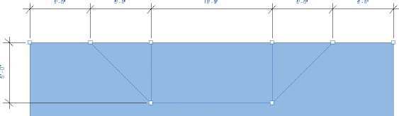
Now that you've added the proper locations to break the slope, you'll modify the points at the ends of the lines to change the slope of the floor. Start by returning to your Default 3D View.
As you hover over the endpoint of the line, Revit highlights the shape handles. Press the Tab key to highlight a specific handle and then select it (Figure 4.9). Now you can adjust the elevation of the shape handle. In this case we're depressing the floor, so the value will have to be negative. But you could also increase the elevation in a small area by using a positive value.
Change the value as shown in Figure 4.9. Then do the same for the shape handle to the right. When you're done, the depressed area will resemble Figure 4.10.
FIGURE 4.9 Editing the shape handle
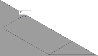
FIGURE 4.10 The finished depression
Creating Openings by Sketching
For the occasional or irregular opening in a floor, it's easy to add a secondary opening using the Opening tool.
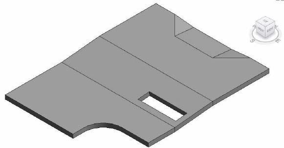
From the Home tab, select the By Face tool from the Opening panel. Then select an edge of the sloped floor slab you created to enter Sketch mode. Now sketch an opening 10′ × 3′ [3 m × 1 m] in the center floor panel.![]()
When you finish the sketch, the result will resemble Figure 4.11. There's no limit to the number of interior sketches that you can create. You can also edit sketches previously created.
FIGURE 4.11 The finished opening
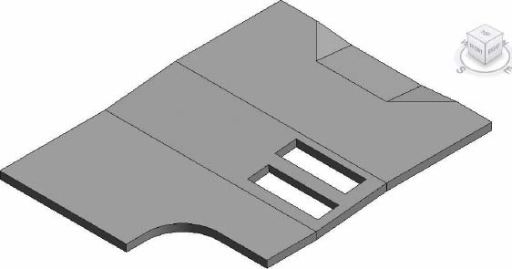
![]() An opening of this type will remain perpendicular to the floor, roof, or ceiling. On the other hand, a vertical opening will remain perpendicular to the level that it was created on. Select the same slab and sketch a new opening of the same size and dimensions to the right of the first one. The result will resemble Figure 4.12.
An opening of this type will remain perpendicular to the floor, roof, or ceiling. On the other hand, a vertical opening will remain perpendicular to the level that it was created on. Select the same slab and sketch a new opening of the same size and dimensions to the right of the first one. The result will resemble Figure 4.12.
FIGURE 4.12 Sketch a new opening of the same size and dimensions.
The differences are subtle but very important. By creating a section through both openings, you can see the difference in an opening that remains perpendicular to the floor compared to one that remains perpendicular to the level (Figure 4.13).
FIGURE 4.13 Finished parallel and perpendicular openings
Keep in mind that from a project management standpoint, if you have a number of openings that are predictably shaped (circular, rectilinear, etc.) and highly repetitive, you'd be better off creating a host- or face-based opening (with parameters for options) as a family component and then loading it for use in your project.
Creating Openings with Shafts
For openings that occur from level to level with vertical regularity (like a shaft or elevator core), you can use the Shaft tool. This tool allows you to create an opening in numerous floors, roofs, and ceilings quickly and easily. Start by adding a few more levels to your project so that you have 10 levels that are evenly spaced.![]()
Select all three floors on Level 1 and copy them by pressing Ctrl+C. Now the geometry is ready to be pasted to each of the levels. The best way to do this is by using the Paste tool, which allows you to select all the levels to which you intend to paste the floors. Select Paste from the Clipboard palette and then select Aligned To Selected Levels (Figure 4.14).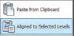
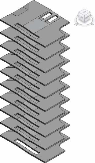
Now you'll be given the option to select all the levels. Select levels 2–10 (Figure 4.15). The resulting floors are shown in the same figure. Return to the Level 1 view and select the Shaft tool from the Opening panel. Once again, you'll enter Sketch mode. Create a new rectangle perpendicular to the last two you just drew. Be sure to modify the top constraint so that the shaft goes up to Level 10. Also be certain to assign a Top Offset value since the upper floor is slightly above the level (Figure 4.15).
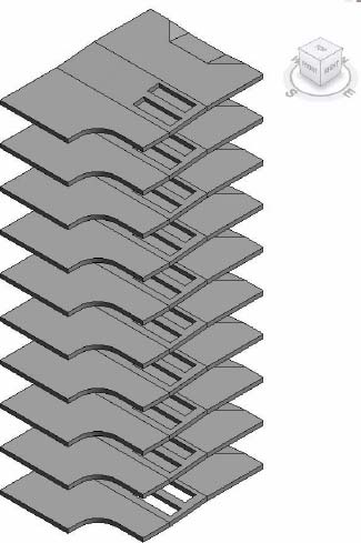
FIGURE 4.15 Creating a multistory shaft

Figure 4.16 shows the resulting shaft in 3D. All the floors were automatically cut. Any ceilings, roofs, and additional floors that may be added in the future will automatically be cut as well.
FIGURE 4.16 The finished multistory shaft
Picking Walls
Selecting walls defines a visual boundary that has been created during the design process; you can also use walls to create floors by using this boundary made by the bordering walls. Let's start by creating a series of walls on Level 1 that resembles Figure 4.17.
FIGURE 4.17 Creating a chain of walls

 Now select the Floor tool to enter Sketch mode. But this time, you don't want to sketch the boundary of the floor manually. There's an easier way. Select the Pick Wall tool from the Draw palette. Doing so allows you to select an individual wall or an entire chain of walls.
Hover over one of the wall edges and then press and release the Tab key. Your selection will “cycle” from one wall to the series of walls. When all of the walls highlight, select them with one pick. Note that the edge of the new floor will be constructed where your mouse clicks when you pick the wall in reference to the interior or exterior of the wall. The floor goes to the outside of the wall; in order to do that, you have to pick the outside edge of the wall—otherwise, the floor aligns with the interior. The entire chain of lines will be created that correspond to all of the walls.
If you move the walls that were used to determine the floor sketch, the boundary of the floor will automatically update. This is incredibly powerful for a multistory building, where updating one floor at a time would be nearly impossible. As soon as one update would complete, the design would have likely changed, requiring you to start over.
Laying Out Roofs
You create roofs much like you do floors: from a sketch resulting from either drawn lines or picked walls. And as with floors, if you pick the exterior walls as a reference, then moving the walls will move the corresponding edges of the roof. Roofs can also be created in elevation (which we'll get to in a bit).
Roofs tend to slope, for a lot of good reasons. Let's create some roofs and investigate a few slope options.
Picking Walls
Let's start by adding a roof to the same walls you used in the previous floor exercise. First, return to your Level 1 plan view. Select the Roof tool and choose Roof By Footprint. At this point, Revit will automatically ask you to select levels this roof is going to be associated with; select Level 3.
Once again, you don't have to pick all the walls individually or sketch all the roof boundary lines. Select the Pick Walls option. Then hover over one of the exterior walls and press the Tab key to select the entire chain. When you select the entire chain of walls at once, all of the roof boundary lines will be created.
Note the icon with the double arrows. Clicking this icon will flip the boundary lines to the inside or outside of the wall face. Click this icon to move all the boundary lines to the inside of the wall's faces.
Since this will be a sloped roof, you can make the slope perpendicular to the left edge by deselecting the Defines Slope check box for all the other lines. Now define the slope of the left edge with a 1/12 rise over run (about 8 percent).
Finish the sketch and look at the project in 3D. While the roof begins at Level 3 and has the proper slope, it's immediately obvious that the walls don't extend beyond the roof.
Revit excels here at helping your team during the design process. Rather than not anticipate a potential conflict, you're able to identify conflicts earlier rather than later so you can resolve them before other design issues create circular conflicts.
Select all the walls (using the Tab key to select the entire chain) and set Top Constraint to Level 4 in the Properties palette. The results will resemble Figure 4.18.
FIGURE 4.18 Adjusting the wall height

![]() Select the roof and reenter Sketch mode. Another option to determine the slope of a roof is using slope arrows. Slope arrows allow you to specify a slope, and they will also allow you to specify the levels of the arrow at both the head and tail.
Select the roof and reenter Sketch mode. Another option to determine the slope of a roof is using slope arrows. Slope arrows allow you to specify a slope, and they will also allow you to specify the levels of the arrow at both the head and tail.
The tail of the slope arrow must reside on the boundary of the sketch. But the head of the slope arrow may point in practically any direction! Add a slope arrow as shown in Figure 4.19. Note the Height Offset At Head value is set to 6′ [ 2m]. Make sure you uncheck the Define Slope option ![]() for the edges of the roof to see the full effect of using the Slope Arrow.
for the edges of the roof to see the full effect of using the Slope Arrow.
When you finish the sketch, you'll notice that a single slope proceeds across the roof. A single slope in this direction would be nearly impossible to specify without slope arrows.
You can create roof slopes using multiple slope arrows. This technique is incredibly helpful when you want to create sloped conditions where two perpendicular slopes must meet at exactly the same location. Again, this is something that's difficult to do without slope arrows.
Let's explore this topic by reentering Sketch mode with the previously created roof. Delete the existing slope arrow by editing the sketch. Now sketch two new slope arrows so that the heads of the arrows meet at the upper-left corner of the roof. The Slope Arrow should have the following properties:
Head Offset At Tail: 0″
Head Offset At Head: 6′ [2 m]
Make sure that Height Offset is the same for both Tails and Heads. When you finish the sketch, the results will resemble Figure 4.20.
FIGURE 4.20 Sketching two slope arrows
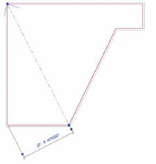
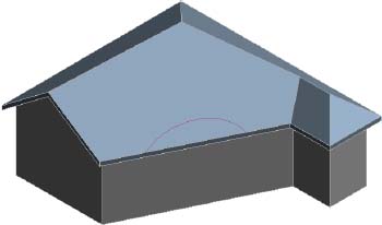
Another common condition in residential-styled roofs is one of multiple slopes that are perpendicular to their many edges. To create this condition, you'll reenter Sketch mode for the previously created roof and start by deleting both the slope arrows.
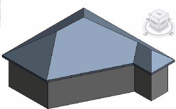
Now select all the lines that represent the roof sketch. You can do this by holding down Ctrl and selecting the lines individually or by clicking on one and pressing Tab to highlight the rest of the lines. Once you have them selected, in the Options Bar, enter 3′ [1 m] for the overhang. Now select the Defines Slope option for all the boundary edges from the Properties palette. Also modify the Slope property for a slope of 9/12. The roof in Sketch mode should look like Figure 4.21. Finish the sketch.
FIGURE 4.21 Offsetting the roof sketch and defining slopes

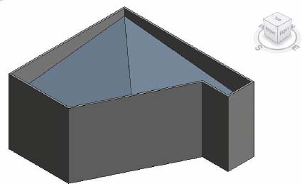
![]() Initially the edges of the wall extend beyond the overhang of the roof. Select all the exterior walls (use the Tab key) and then select the Attach Top/Base option on the Modify | Wall tab. The result will resemble Figure 4.22.
Initially the edges of the wall extend beyond the overhang of the roof. Select all the exterior walls (use the Tab key) and then select the Attach Top/Base option on the Modify | Wall tab. The result will resemble Figure 4.22.
FIGURE 4.22 Attaching the walls to the roof
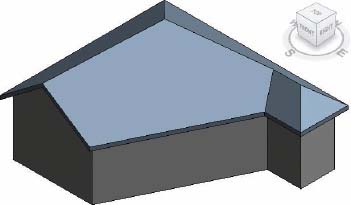
The great thing about attaching walls is that if the roof's angle or slopes change, the walls will automatically react to the new condition. To test this, reenter Sketch mode and remove the Defines Slope option for one of the edges.
When you finish the sketch, the results will resemble Figure 4.23. Since the walls have previously been told to attach to the roof, the gable condition is already updated.
FIGURE 4.23 Removing a defined slope
Extruded Roofs
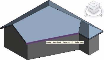
In addition to being able to create roofs in a plan or footprint orientation, you can extrude roofs from vertically planer surfaces. To do so, first select the Roof By Extrusion command from the Roof flyout on the Home tab. Once you select this command, you'll be immediately prompted by Revit to select the plane from which the extruded roof will spring. Select the face of the roof highlighted in Figure 4.24.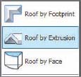
FIGURE 4.24 Defining the slopes
Now you'll be prompted to associate the roof to the appropriate level. This step is important for scheduling purposes and you can modify the value later. For now select Level 3 since it's closest to the base of the extruded roof.
Next, you'll create the sketch for the extruded roof. The sketch line will not be a closed loop. It's just a line (or series of connected lines) that defines the top of the extruded roof. For this example, you'll create an arc. Select the Arc tool from the Draw panel ![]() .
.
Now create the arc approximately as shown in Figure 4.25. The important detail is that we're going to set the Extrusion End to 20′-0″ [6 m].
FIGURE 4.25 Creating the sketch
When you complete the sketch, the roof is springing from the arc that you created. But it's not reaching back and connecting to the roof face. This issue is easy to resolve. First, select the roof and then select the Join/Unjoin Roof option on the Geometry panel. Then, hover over the rear edge of the extruded roof, as shown in the left image of Figure 4.26. Finally, select the face of the previously created roof that you want to connect the extruded roof.
FIGURE 4.26 Attaching the Roof
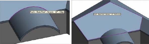
The extruded roof will now extend back to meet the face of the other roof (Figure 4.27). If either roof is modified, Revit will do its best to maintain this connected relationship.
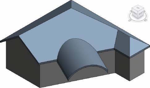
Overall, there are so many other complex areas that we can talk about with regard to roofs, starting with point elevations and then digging into more instance and type parameters. But once again, this is beyond the space limitations for an introduction to Revit. Learning how to use Revit organically is a better approach: Start with the basics of design iteration and then build on these concepts as the need arises.
Adding Ceilings
Ceilings in Revit are easy to place as well as modify. As you move the walls, the ceiling associated to those walls will stretch to fit their new conditions.
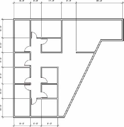
Let's start by returning to the Level 1 floor plan of the previous exercise. Add 10′-0″ [3 m] high walls and doors to create individual, shared, and open spaces (Figure 4.28).
FIGURE 4.28 Level 1 with walls
Automatic Ceilings
The Ceiling tool is found on the Build palette of the Home tab. When you select the tool, the default condition is Automatic Ceiling. This means that as you hover over a space, Revit will attempt to find the boundary of walls. Let's do this for one space (Figure 4.29). As you hover over the space, Revit indicates the boundary with a broad, red line. As you can see, Revit offers four default ceiling types: one Basic type and three Compound types. Let's select the 2′ × 2′ [600 mm × 600 mm] system.
FIGURE 4.29 Placing the ceiling

As you place the first ceiling in the Floor plan view, you'll get a warning. This happens frequently and for good reason. You've placed the ceiling but you can't see it. As a rule, you should not ignore warnings. We've seen people click and click only to find that they've repeatedly placed ceilings in the same space.
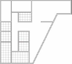
Go to the proper view in the Project Browser to see the ceiling—in this case the ceiling plan for Level 1. Now you can plainly see the ceiling that you've created. Let's automatically place the remaining ceilings as shown in Figure 4.30. Notice that Revit will center the grid based on the space that you've selected.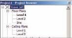
Sketching Ceilings
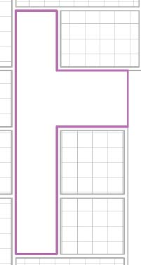
Next, you'll place ceilings in the upper-left corner of the ceiling plan for Level 1, but this time you'll share the ceiling between the two spaces. This practice is common in interior projects. The partitions only extend to the underside of the ceiling (rather than connect to the structure above). Begin by selecting Sketch Ceiling on the Ceiling panel. Add sketch lines as shown in the first image in Figure 4.31. The result is shown in the second image.
FIGURE 4.31 Sketching the ceiling
Now let's place a ceiling in the upper right of the plan, but this time you'll sketch a 2′ × 4′ [1.2 m × 600 m] system (Figure 4.32). Choose this new system from the Type Selector before you finish the sketch of the ceiling.
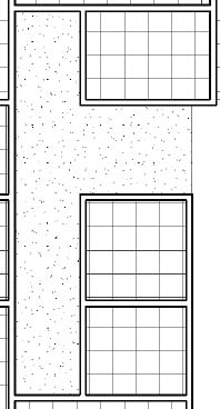
And finally, create a GWB on Mtl. Stud Ceiling for the area shown in Figure 4.33.
FIGURE 4.33 Creating a GWB on Mtl. Stud Ceiling
By default, the GWB material doesn't have a surface pattern. While this material would be too graphically busy for walls, it will be fine for ceilings. So let's create a new material for GWB associated to ceilings and give it a pattern.
Select an edge of the ceiling and click Edit Type. Then click the Structure button to open the Edit Assembly window. Select the Gypsum Wall Board material option and duplicate the existing material. Name the new material Gypsum Ceiling Board. Now associate a surface pattern called Sand to the material. Click OK until you close all the dialog boxes and return to the Ceiling plan view. The result is shown in Figure 4.34. You can now distinguish the ceiling from the open areas that have no ceiling.
FIGURE 4.34 Assigning materials to a ceiling
Bulkhead Conditions
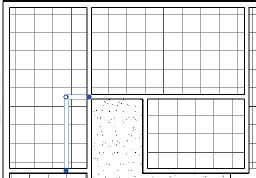
Creating a bulkhead to separate two ceilings is straightforward. To begin, place the walls that will act as the bulkhead, as shown in Figure 4.35. Be sure to set the Base Offset value of the walls to 7′-9″ [2.3 m] and the Unconnected Height value to 2′-3″ [700 cm]. This will create two walls above head height.
FIGURE 4.35 Creating a bulkhead
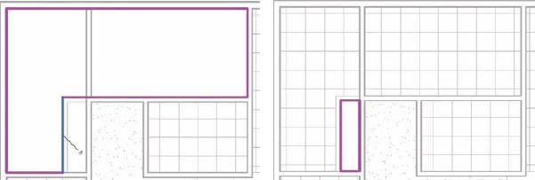
It requires a bit of finesse to delete or edit a placed ceiling. Most beginners simply select the grid. But you actually need to select the edge of the ceiling to edit it. Hover over the edge of the ceiling and use the Tab key to cycle through options until the edge of the ceiling is highlighted. Then select it and choose Edit Boundary. Modify the ceiling as shown in Figure 4.36. Sketch a new GWB ceiling that is 9′-0″ [2.7 m] and finish the sketch. The second image in Figure 4.36 shows the finished ceiling.
FIGURE 4.36 Editing the boundary
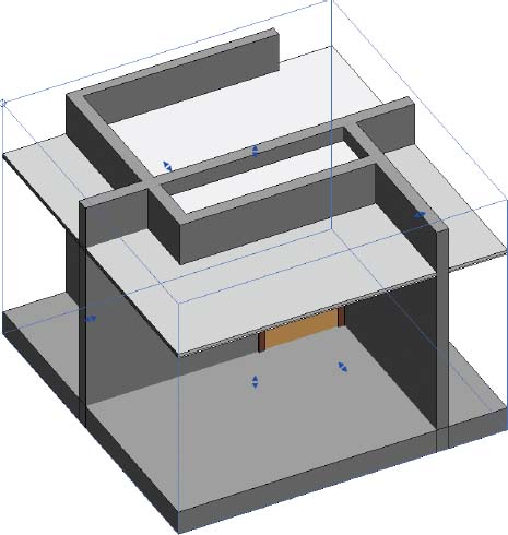
To get a better idea of the finished configuration in 3D, go to a 3D view and orient a section box of the Level 1 plan view. Right-click the ViewCube and from the Floor Plans flyout of the context menu, select Level 1. Use the grip arrows to pull the boundaries of the section box to resemble Figure 4.37. You'll find that working this way is helpful because having both 2D and 3D views aids in communicating the design issues.
FIGURE 4.37 Orienting the section box to the 3D view
Adding Lights and Rotating the Grid
Adding lights is easy and since they're hosted by the ceiling, lights will often create openings for you. Let's begin by loading one of the lighting families.
From the Insert tab, select Load Family from the Load From Library panel. Open the Lighting Fixtures folder and double-click on the family Ceiling Light – Linear Box.rfa.
You'll be prompted to place the first family type of the family in your ceiling, but be sure to select the 2′ × 4′ type from the Type Selector. You'll place lighting fixtures into the 2′ × 4′ ceiling in the upper-right ceiling plan.
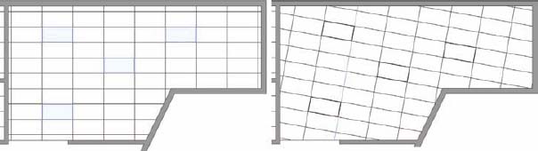
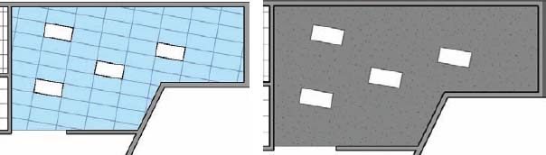
As you will notice, the insertion point for the light is the center of the light. So place the first light and then use the Align tool to get the first one into the right spot. Then copy the first light based on the intersection of the ceiling grid. All of the lights are shown in Figure 4.38 on the left. To rotate the grid, select any grid line and use the Rotate tool rotate the grid line. In this case, we specified a 10-degree angle. You'll notice the lights have rotated as well.
Now press and drag the ceiling grid lines to better center the lights in the overall space. Again, the lights have moved with the grid. This technique is incredibly helpful for maintaining design coordination. The finished condition is in Figure 4.38 on the right.
FIGURE 4.38 Placing lights and rotating the grid
Changing the Ceiling
Ceiling types often change in the design process. Again, where most beginners struggle is mistakenly selecting the ceiling grid (which is actually selecting the material). But you need to select the geometry of the ceiling, which you do by selecting the edge of the ceiling.
Select the edge of the ceiling and then you'll be able to pull down the Properties menu to select the GWB option for this ceiling (Figure 4.39). The result is shown in the second image in Figure 4.39.
FIGURE 4.39 Selecting ceiling geometry
Sloping the Ceiling
We can even slope the ceiling by placing a slope arrow while editing the boundary of the ceiling. This is basically the same process as sloping a floor or a roof.
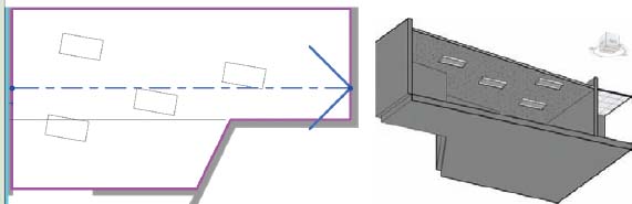
Select the edge of the ceiling and choose Edit Boundary. Place a slope arrow as shown in Figure 4.40. Then set the Height Offsets for the Tail and Head to 0 and 3′ [1 m], respectively. Finish the sketch. The result is shown 3D using a section box. The lights even follow the revised ceiling slope!
FIGURE 4.40 Adding a slope arrow to the ceiling
THE ESSENTIALS AND BEYOND
In this chapter you learned to create floors, lay out roofs, and add ceilings.
ADDITIONAL EXERCISES
- Create a mass and intersecting levels and then create mass floors from those levels. Use the mass floors to create a Floors By Face.
- Modify the mass from the previous step and then update the Floors By Face.
- Create a shaft opening and intersect it with all the Floors By Face from the previous step.
- Create a Roof or Floor and then use the Shape Editing tools to model slopes for drainage.