
10
Inventor iLogic Fundamentals — Creating Process Automation and Configurations
The iLogic functionality within Autodesk Inventor enables designers and engineers to create rules that drive model geometry, parameters, and behavior, all from a user-friendly interface utilizing VB.NET code.
iLogic rules are created and organized using built-in snippets and other code statements to run functionality within a part’s file, assembly, or drawing. The scope of what can be achieved with iLogic is immense: complete model configurations can be created using rules that define the shape, size, suppression or unsuppression of features, material type, and more. iLogic can also be used for drawing layouts and assembly nomenclature. iLogic rules can be run internally and manually inside a file, externally from the file, or configurations can be driven from iLogic forms or triggers in the file.
iLogic’s core purpose and functionality is to provide a level of automation and intelligence to digital CAD models, enabling engineers to readily generate configurations. It resides within the core Inventor product, out of the box, and does not require additional purchases or installation.
In terms of incorporating intelligence into designs, there is a progression of solutions in terms of levels of complexity:
- Parameters and equations
- iFeatures, iParts, iAssemblies, and spreadsheet-driven models
- iLogic
- VBA Macros and apps developed in the Inventor API
In this chapter, we will focus on the third level, iLogic. You must have a good understanding of the functionalities outlined in levels 1 and 2 before proceeding with this chapter, as knowledge and experience in practical terms with these functionalities is essential for understanding and utilizing iLogic.
iLogic may seem a little intimidating to readers who have no experience in coding, but this need not be the case. The iLogic environment and use of snippets (ready-made pieces of code) make using iLogic out-of-the-box simple, and no previous coding experience is required.
In this chapter, we will cover the following topics:
- Understanding the fundamentals and usage of iLogic
- Creating a configurable part with iLogic rules
- Creating a configurable assembly with iLogic
- Creating an iLogic form and Event Triggers
Technical requirements
To complete this chapter, you will need access to the practice files in the Chapter 10 folder within the Inventor Cookbook 2023 folder. It is important that you have a good understanding of equations, parameters, iFeatures, iParts, and iAssemblies before proceeding. You can find information on these topics in Chapter 3, Driving Automation and Parametric Modeling in Inventor.
Understanding the fundamentals and usage of iLogic
In this recipe, you will learn how to operate and utilize an existing iLogic assembly of a ladder. You will become familiar with the iLogic browser and how you can access and edit rules to construct models. You will also make changes to the assembly using the predefined iLogic form.
iLogic itself is a large topic, but this chapter aims to introduce readers to the core functionalities. Here are some common areas where iLogic is utilized:
- Suppress or unsuppress parts or features
- Control assembly constraints
- Run multiple operations on a single input
- Make configurations
- Update iProperties of models
- Work with iFeature, iParts, and iAssemblies
- Control drawing borders and title block information
As with most features and functionality in Inventor, there is a recommended workflow. For iLogic, this is as follows:
- Create and define the model.
- Create the iLogic rules.
- Set rule triggers (if applicable).
- Edit rules.
- Create an iLogic form (if applicable).
As iLogic rules mainly run from existing equations and parameters defined during the creation of the model, it is very important that from the outset, the model has been properly defined at all stages, and there are no unresolved parts, mates, or missing geometry/undefined sketches. The base model must be solid before progressing with the implementation of iLogic rules.
It is also advisable to have set goals and objectives of what you want your end part or configuration to be. Mapping out the options prior to starting will make the process of applying iLogic code much easier.
Creating the rules is done in the iLogic environment of Inventor. A single rule or multiple rules can be defined, and there is no limit to the number of rules that can be applied. A single rule can in fact run multiple operations. Rules can be contained within the relevant file or externally, and at any point, rules can also be edited. Conditional statements such as the following form the basics of most iLogic rules:
If (Something) = True Then
 (Do Something)
Else
  (Do Something Else)
End If
What makes iLogic easy to configure is that Inventor already has a library of snippets – pre-defined VB.NET code statements that can be applied and edited to define the rules. You can of course create your own from scratch.
When editing the rules, the model may have to be flexed and tested with the rule to ensure that it is working to the desired outcome.
Within Inventor, there are two types of iLogic rules, internal and external. Both are created within the context of Inventor, inside the iLogic browser. Internal rules are rules that are created and stored within the context of a file. External rules are not stored within Inventor files, but in a local or networked directory.
Internal rules are accessible to users that have permission to access those files. External rules have an added level of security in that they are stored in a directory either locally on a user system or centrally on a server. It is up to you to decide which type of rule you wish to create, depending on the objective.
Getting ready
Navigate to Inventor Cookbook 2023 | Chapter 10|iLogic Access Ladder.
How to do it…
To start the recipe, we will open the model and observe the predefined form that appears:
- Open the Access Ladder.iam file in Inventor.
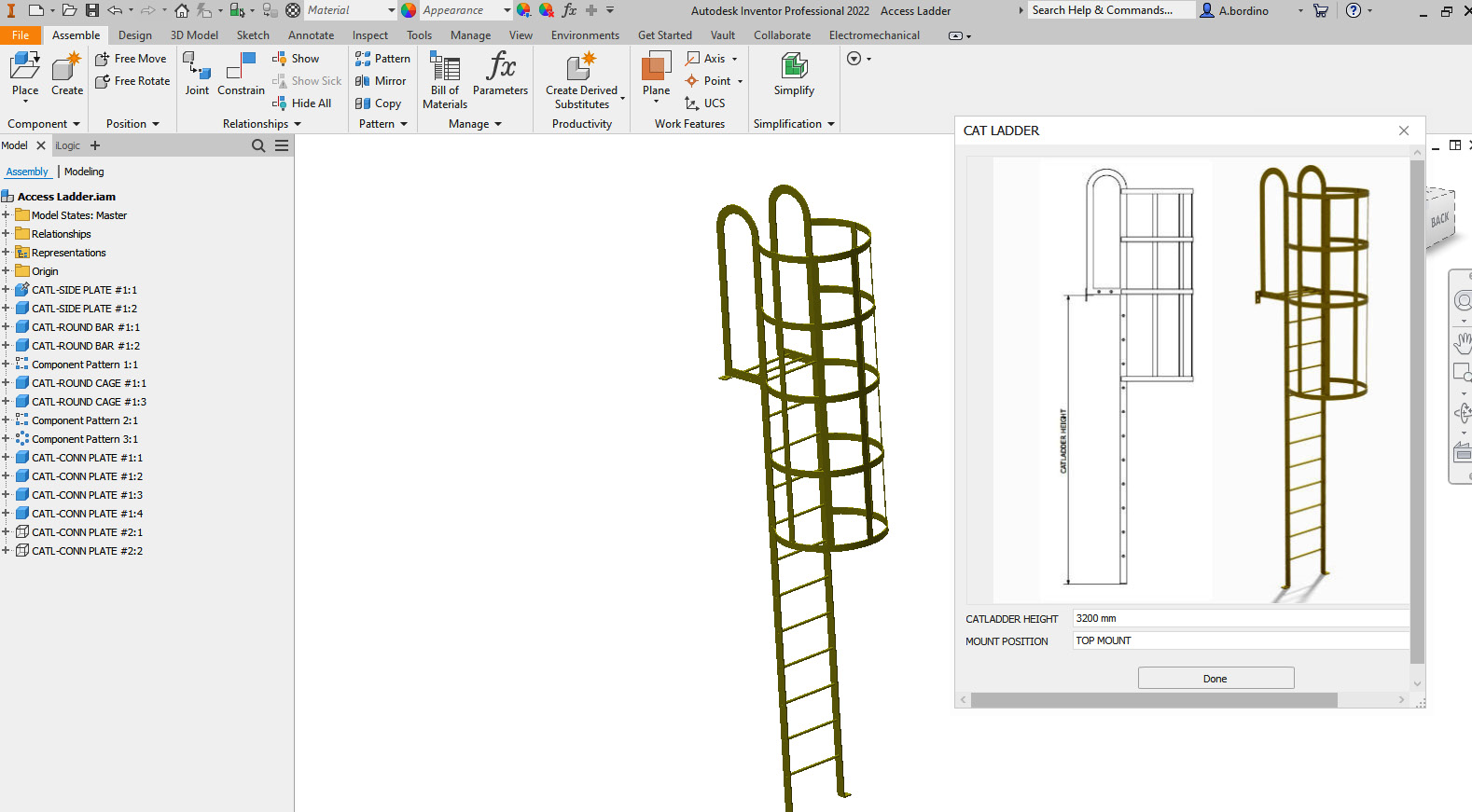
Figure 10.1: Access Ladder assembly open with the iLogic form to the right
Upon opening the file in Inventor, you will see the model displayed in the default state at the Origin. You will also notice that an iLogic form is visible and open. This iLogic form has been created to control the two internal iLogic rules within the file so that you can configure the Access Ladder.iam file efficiently without editing the VB.NET code of the rules.
In this example, you can either adjust the HEIGHT or MOUNT POSITION of the access ladder.
- Select the dropdown next to MOUNT POSITION and select SIDE MOUNT.
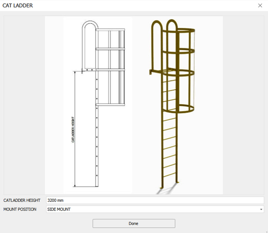
Figure 10.2: SIDE MOUNT selected on the iLogic form
Once SIDE MOUNT is selected, the assembly updates automatically to display a side mounting plate.
- Select LADDER HEIGHT and type 1500mm. The model updates as shown in Figure 10.3. Access Ladder.iam is shortened to 1500mm in length and the guard is removed as dictated by the iLogic rules. To close the iLogic form, select Done.
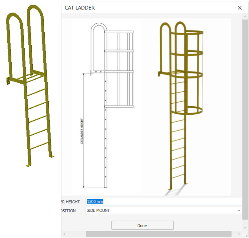
Figure 10.3: Updated iLogic form and assembly
- We will now access the iLogic rules themselves and understand how they operate. From the Model Browser, select the iLogic tab to open the iLogic browser.
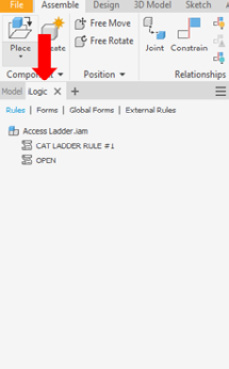
Figure 10.4: iLogic browser selected
- Clicking on Rules displays active rules within this file. From the list, we have two rules that are active: CAT LADDER RULE #1 and OPEN. Right-click on OPEN and select Run Rule. The iLogic form will appear on the screen. This rule is used to open the iLogic form as the Access Ladder.iam file is opened so that the user can begin configurations immediately.
- Right-click on CAT LADDER RULE #1 and select Edit Rule. The Edit Rule menu now opens:

Figure 10.5: Edit Rule menu open for CAT LADDER RULE #1
- This environment is where you can create, edit, and define the iLogic rule functionality. As Figure 10.5 shows, it’s quite a busy menu, so let’s break it down by looking at Figure 10.6:

Figure 10.6: Edit Rule menu areas
This is what each menu area in Figure 10.6 means:
- This section is where we can access features, parts, parameters, and equations that make up the parts in our assembly. You can actively select and reference parameters, equations, dimensions, or other model features for use in your iLogic rule. Ultimately, it is parameters and equations that will provide the building blocks to most rules.
- This is where the iLogic VB.NET code is written and displayed. This is where most of the work to create the iLogic rule takes place. There are tools to enable you to cut, paste, comment, and easily apply If Then and End If statements, operators, and keywords to help you build code and functionality quickly.
- The Snippets area is where we can browse an existing library of readymade snippets of VB.NET code that you can paste, edit, and use within section B of Figure 10.6 to develop the iLogic rules.
Look closely at the start of the code in Figure 10.7. We will now break down what the code means and how it is driving the model.
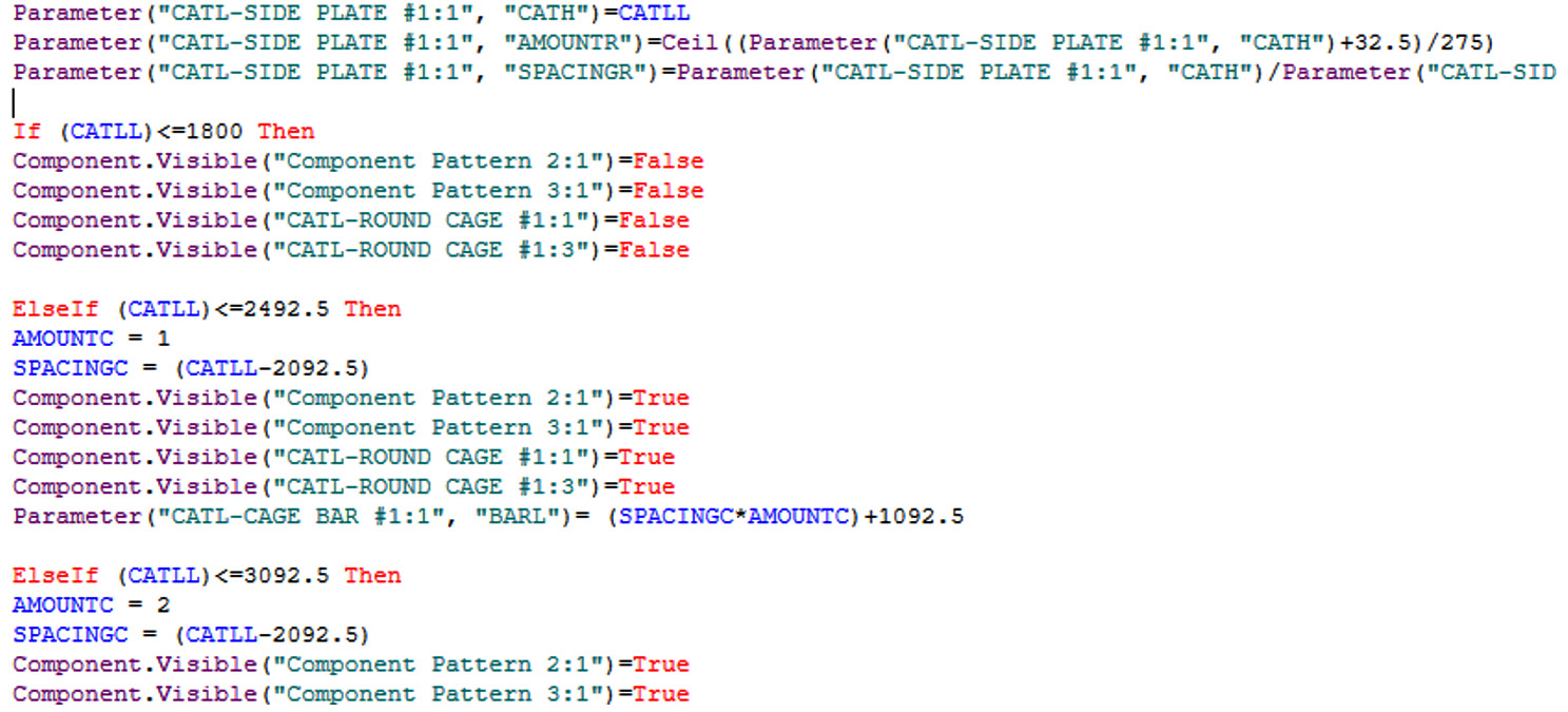
Figure 10.7: Close-up of the code we will examine
The first three lines of code define how certain parameters will work:
Parameter("CATL-SIDE PLATE #1:1", "CATH")=CATLL
Parameter("CATL-SIDE PLATE #1:1",
  "AMOUNTR")=Ceil((Parameter("CATL-SIDE PLATE #1:1",
  "CATH")+32.5)/275)
Parameter("CATL-SIDE PLATE #1:1",
  "SPACINGR")=Parameter("CATL-SIDE PLATE #1:1",
  "CATH")/Parameter("CATL-SIDE PLATE #1:1", "AMOUNTR")
These sections define how the ladder rungs are placed in terms of the number and spacing.
Next are End If/Else If statements, which define how these parameters should behave, depending on the critical CATLL value (which is the ladder’s height) entered in the iLogic form:
If (CATLL)<=1800 Then
Component.Visible("Component Pattern 2:1")=False
Component.Visible("Component Pattern 3:1")=False
Component.Visible("CATL-ROUND CAGE #1:1")=False
Component.Visible("CATL-ROUND CAGE #1:3")=False
This states that if the value of CATLL (the ladder height) is less than 1800mm, then the following features are to be suppressed, and this includes the round protective cage. This is what we demonstrated in step 3 when we defined LADDER HEIGHT as 1500mm in the iLogic form.
The next portion of the code states that if the value of LADDER HEIGHT is set to <2492.5, then create the cage but only with the values and spacings shown here:
ElseIf (CATLL)<=2492.5 Then
AMOUNTC = 1
SPACINGC = (CATLL-2092.5)
Component.Visible("Component Pattern 2:1")=True
Component.Visible("Component Pattern 3:1")=True
Component.Visible("CATL-ROUND CAGE #1:1")=True
Component.Visible("CATL-ROUND CAGE #1:3")=True
Parameter("CATL-CAGE BAR #1:1", "BARL")=
  (SPACINGC*AMOUNTC)+1092.5
The next parts of the preceding code starting with Component.Visible are to calculate the size of the round cage section as the height of the ladder increases.
This next section of code defines how the side or top mounting plates are visible; it relates to the drop-down menu in the iLogic form, defining which components are visible or suppressed:
If BASE1 = "TOP MOUNT " Then
Component.Visible("CATL-CONN PLATE #1:1")= True
Component.Visible("CATL-CONN PLATE #1:2")= True
Component.Visible("CATL-CONN PLATE #2:1")= False
Component.Visible("CATL-CONN PLATE #2:2")= False
End If
If BASE1 = "SIDE MOUNT" Then
Component.Visible("CATL-CONN PLATE #1:1")=False
Component.Visible("CATL-CONN PLATE #1:2")=False
Component.Visible("CATL-CONN PLATE #2:1")=True
Component.Visible("CATL-CONN PLATE #2:2")=True
The final section of code sets a limit to the configuration in that if a value for LADDER HEIGHT in the iLogic form is set to <18,000, then the model displays a working error message "TOO BIG, LOWER LADDER HEIGHT", "ERROR":
If (CATLL)>18000 Then
MessageBox.Show("TOO BIG, LOWER LADDER HEIGHT",
  "ERROR")
End If
This communicates to the user that a lower value must be entered to proceed and compute.
- We will now test the final line of code. Select Close in the Edit Rule menu.
- From the iLogic browser, select Forms, then CATLADDER.
- Choose CATLADDER HEIGHT and enter a value of 20,000. Hit Enter.

Figure 10.8: ERROR message displayed
The rule is executed as soon as the value is higher than 18,000, displaying the warning message.
- Now we will add an additional element to the rule that changes the color of all components of the configuration when it is greater than 3092.5 in length. Select the iLogic browser, right-click on CAT LADDER RULE #1, and select Edit Rule.
Scroll down the code until you reach the section shown in Figure 10.9 and select where the arrow is pointing. This is where the cursor will then deploy, and we will write new functionality within the rule.
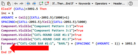
Figure 10.9: Section in the rule where we will write new code
- Hit Enter a few times to create some space between the sections of code. It is important to keep your code organized neatly, as this makes understanding it and future edits much easier.
- Select If…Then…End If, from the toolbar in Rule Editor. This adds the conditional statement to your code without you having to type anything. This is the basis of our new function within the rule.

Figure 10.10: If…Then…End If statement added to the code
- We now need to change My-Expression to a parameter and a value. Select My_Expression and type If (CATLL) >3092.5 Then. This states that if the CATLL parameter value entered is greater than 3092.5 then do something.
- Now we must define what it is exactly we want the code to do when the value of the CATLL parameter reaches the threshold. After Then in the code, hit Enter to start a new line.
- In the Snippets area of the Edit Rule window, select the Components folder, and select Color by double-clicking. The default snippet is inserted into the code. This snippet allows us to define what color the component should change to when the rule is executed.
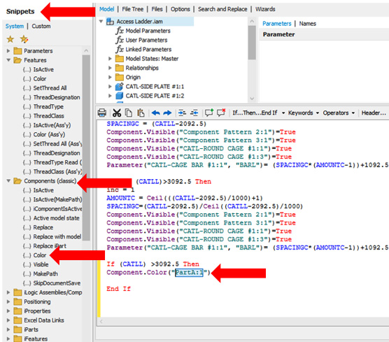
Figure 10.11: Component.Color snippet added to the code
- Change Component.Color("PartA:1") to Component.Color("CATL-SIDE PLATE #1:1") = "Cyan". Now we have defined the component that we want to change the color of when the rule is run, and we have specified a color found in the Appearance Library.
We now need to repeat this for all other components we want to follow this rule. Add additional lines of code as follows. You can view the components in the model in the Model and File Tree area of the Edit Rule menu, shown as section A in Figure 10.6.
Type the following code into the iLogic Rule, or use copy and paste from CAT LADDER #1 iLOGIC RULE COMPLETE.txt in the iLogic AccessLadder folder:
If (CATLL) >3092.5 Then
Component.Color("CATL-SIDE PLATE #1:1") = "Cyan"
Component.Color("CATL-SIDE PLATE #1:2") = "Cyan"
Component.Color("CATL-ROUND BAR #1:1") = "Cyan"
Component.Color("CATL-ROUND BAR #1:2") = "Cyan"
Component.Color("Component Pattern 1:1") = "Cyan"
Component.Color("CATL-ROUND BAR #1:1") = "Cyan"
Component.Color("CATL-ROUND BAR #1:2") = "Cyan"
Component.Color("CATL-ROUND CAGE #1:1") = "Cyan"
Component.Color("CATL-ROUND CAGE #1:3") = "Cyan"
Component.Color("Component Pattern 2:1") = "Cyan"
Component.Color("Component Pattern 3:1") = "Cyan"
Component.Color("CATL-CONN PLATE #1:1") = "Cyan"
Component.Color("CATL-CONN PLATE #1:2") = "Cyan"
Component.Color("CATL-CONN PLATE #1:3") = "Cyan"
Component.Color("CATL-CONN PLATE #1:4") = "Cyan"
Component.Color("CATL-CONN PLATE #2:1") = "Cyan"
Component.Color("CATL-CONN PLATE #2:2") = "Cyan"
End If- With all the components that we want to change the color of defined for this rule, select Save & Run. Inventor will check your code for errors and syntax before completing and will warn you if there are any errors. Be mindful as spelling is key here. Close the Edit Rule menu. We will now test the new piece of code.
- Open the iLogic form for the Access Ladder.iam file. Set CATLADDER HEIGHT to 3500. Hit Enter. The model updates as per the code and all components turn cyan in color. The rule has run successfully with the edits we made.
In the iLogic form, change CATLADDER HEIGHT to 2200 and hit Enter. The model updates correctly in terms of geometry, but the color for all components is left as cyan. Our rule stated that this should only occur if the value of CATLADDER HEIGHT is greater than 3092.5. This is because we are lacking an Else If statement in our code. We need to define all possible scenarios so that if the value is not greater than 3092.5, then the color should be Canary.
- In the iLogic Browser, right-click CAT LADDER RULE #1 and select Edit Rule.
- Add the following after Component.Color("CATL-CONN PLATE #2:2") = "Cyan":
Else
Component.Color("CATL-SIDE PLATE #1:1") = "Canary"Component.Color("CATL-SIDE PLATE #1:2") = "Canary"Component.Color("CATL-ROUND BAR #1:1") = "Canary"Component.Color("CATL-ROUND BAR #1:2") = "Canary"Component.Color("Component Pattern 1:1") = "Canary"Component.Color("CATL-ROUND BAR #1:1") = "Canary"Component.Color("CATL-ROUND BAR #1:2") = "Canary"Component.Color("CATL-ROUND CAGE #1:1") = "Canary"Component.Color("CATL-ROUND CAGE #1:3") = "Canary"Component.Color("Component Pattern 2:1") = "Canary"Component.Color("Component Pattern 3:1") = "Canary"Component.Color("CATL-CONN PLATE #1:1") = "Canary"Component.Color("CATL-CONN PLATE #1:2") = "Canary"Component.Color("CATL-CONN PLATE #1:3") = "Canary"Component.Color("CATL-CONN PLATE #1:4") = "Canary"Component.Color("CATL-CONN PLATE #2:1") = "Canary"Component.Color("CATL-CONN PLATE #2:2") = "Canary"End If
This informs Inventor that if the value is less than 3092.5 in the iLogic form, then the Component Color of all components must be set to Canary.
- Now we need to check the entirety of the code. Ensure that your code matches the completed code in Inventor Cookbook 2023 | Chapter 10 | iLogic Access Ladder | CAT LADDER #1 iLOGIC RULE COMPLETE.txt.
Once your code matches that of the preceding .txt file, select Save & Run. Close the Edit Rule menu. The assembly should update with all components canary in color. In the iLogic form, set CATLADDER HEIGHT to 3100 and hit Enter. The model geometry updates and the color is changed back to cyan.
You have configured an iLogic model using an iLogic form to drive an Inventor assembly with more than one iLogic rule. You have also edited one of the rules to add additional functionality using snippets, and If Then/End If conditional statements, to drive a global color change across all components in the assembly, depending on user input of one of the parameters through the iLogic form.
Creating a configurable part with iLogic rules
In this recipe, the objective is to take an existing support bracket design with existing parameters and equations defined and create a new iLogic rule with multiple functions that can generate three different design variants: Heavy, Regular, and Light. The rule will be run through a custom user-defined multi-value parameter.
Getting ready
To start the recipe, we will open the model and examine the existing equations and parameters that have been set. We will also establish the design criteria for the finished parts and what the final configurations will look like.
How to do it…
To begin this recipe, you will need to navigate to Inventor Cookbook 2023 | Chapter 10 | iLogic Support Bracket and open Support Bracket.ipt:
- Open Support Bracket.ipt.
The bracket is displayed in its default regular arrangement. 3D annotations are visible in the Graphics window to illustrate the changes in dimensions. In Figure 10.12, you can see the three design variants (Light, Regular, and Heavy) that we will generate from the iLogic rule that we will create.
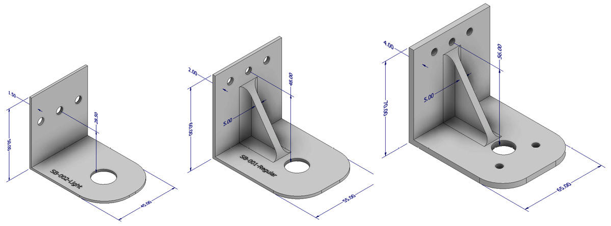
Figure 10.12: Final configurations of each support bracket generated by the iLogic Rule: Light, Regular, and Heavy
- There are currently no iLogic rules defined in this model. Select the Manage tab, and select Parameters. We will now examine the existing equations and parameters that are present and how they control the behavior of the model.
Looking at the existing equations, you can see that the height value is of great importance and is featured throughout many of the equations. It is this primary dimension that drives most of the parameters and thus the behavior in the model.

Figure 10.13: Parameters and equations in the model
Now we will create a user-defined parameter that will enable us to choose between Light, Regular, and Heavy variants of the bracket. This user-defined parameter is what we will reference in the iLogic rule that we will create.
- In the Parameters window, click the drop-down arrow next to Add Numeric and select Add Text.
- Rename User Parameter BracketType. Right-click on Text in the Unit/Type column for BracketType and select Make Multi-Value from the options.

Figure 10.14: User-defined parameter BracketType created and Make Multi-Value selected
- Value List Editor opens. Type Light, Regular, and Heavy into the Add New Items section and select Add. Then select OK.
The multi-value options defined in the preceding step are added to the user-defined custom parameter: BracketType.
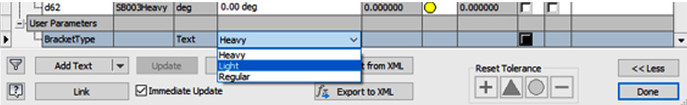
Figure 10.15: Multi-value options for BracketType added
- Cycling through the options currently will have no effect on the model as an iLogic rule driving the changes has not yet been specified. Change the value to Regular as this model is currently in the state of the Regular bracket. Select Done to close the Parameter window.
- Select the iLogic tab next to the Model tab in the Model Browser. Right-click on the empty space and select Add Rule. We will now define the rule to create the configurations.

Figure 10.16: Add rule
- Name the rule Bracket Config and select OK.
Before starting the rule, we will outline our objective and design requirements as comments first. Comments are non-actionable pieces of code that enable you to communicate information in iLogic rules. It is good practice to do this because in the future, if further edits are required, you will be able to get a good understanding of the purpose of the rule without needing to read through the whole code. Comments are also helpful for structuring your iLogic code. Neat and tidy code is good code!
- Type the following into the code writing area (you can also copy and paste this section from the support bracket.dox file into the iLogic Support Bracket folder):
'An iLogic Rule To define 3 Variants of the Support
Bracket .ipt
'Light, Regular and Heavy BracketType
'Regular
'Light
'Heavy
'Regular =
'Height Of 60
'Rib Active
'Material Thickness Of 2 mm
'Additional Support Holes Inactive On rounded plate
'SB-001-Regualar Serial Number Stamped
'Light =
'Height Of 50
'Rib Inactive
'Material Thickness Of 1.5 mm
'Additional Support Holes Inactive On rounded plate
'SB-002-Light Serial Number Stamped
'Hole Height On back plate lowered 10mm
'Heavy =
'Height Of 70
'Rib Active
'Rib Fillet Active
'Rib Thickness 5mm
'Material Thickness Of 4 mm
'Additional Support Holes Active On rounded plate
'SB-003-Heavy Serial Number Stamped
'Hole Height On back plate lowered 10mm
- This now defines what we want to achieve in the iLogic rule. Select all the code and select Comment out the selected lines to turn the text into a comment within the rule. This is shown in Figure 10.17.

Figure 10.17: Comment out the selected lines
- We will now start to write functionality into the iLogic rule, starting with a conditional statement. The first section of the code will define the Regular support bracket configuration. Place the cursor after the comment section and hit Enter twice.
- Type the following commands into the code area:
'Regular Bracket Config
If BracketType = "Regular" Then
    Height = 60
    Thickness = 2
' Rib and Hole feature controls:
Feature.IsActive("Rib") = TrueFeature.IsActive("Hole3") = FalseFeature.IsActive("Mirror1") = FalseFeature.IsActive("Hole2") = TrueFeature.IsActive("Rectangular Pattern1") = TrueFeature.IsActive("Rectangular Pattern2") = TrueHoleHeight = 10
' Serial Number:
Feature.IsActive("SB001Regular")=True
Let’s break down the code. The following segment of code states that if the part is set to Regular, then the Height must be 60 and the Thickness of the material must be 2 mm:
If BracketType = "Regular" Then Height = 60 Thickness = 2
The following segment controls what features are to remain active or inactive at the selection of the Regular variant:
Rib and Hole feature controls:
    Feature.IsActive("Rib") = True
    Feature.IsActive("Hole3") = False
    Feature.IsActive("Mirror1") = False
    Feature.IsActive("Hole2") = True
    Feature.IsActive("Rectangular Pattern1") = True
    Feature.IsActive("Rectangular Pattern2") = True
    HoleHeight = 10
This mainly controls the size and positioning of the central rib and hole features.
The final section enables the correct serial number to be displayed on the bracket:
Serial Number:
Feature.IsActive("SB001Regular")=True- Now highlight the section of iLogic code that you created in step 12. Copy and paste a new instance of this below the previous code added. Then change the values and statements of the copied code to detail the Light variant of the configuration; it should look like the following code:
Light Bracket Config:
Else If BracketType = "Light" Then
Height = 50
Thickness = 1.5
' Rib and Hole feature controls:
Feature.IsActive("Rib") = FalseFeature.IsActive("Hole3") = FalseFeature.IsActive("Mirror1") = FalseFeature.IsActive("Hole2") = TrueFeature.IsActive("Rectangular Pattern1") = TrueFeature.IsActive("Rectangular Pattern2") = TrueHoleHeight = 20
' Serial Number:
Feature.IsActive("SB001Regular") = FalseFeature.IsActive("SB002Light")=True - Copy the preceding snippet of code for Heavy Bracket Config and paste below the previous code as before. Then change the values to Heavy and change Height, Thickness, and all other values as per the following code:
'Heavy Bracket Config
Else If BracketType = "Heavy" Then
Height = 70
Thickness = 4
' Rib and Hole feature controls:
Feature.IsActive("Rib") = TrueFeature.IsActive("Hole3") = TrueFeature.IsActive("Mirror1") = TrueFeature.IsActive("Hole2") = TrueFeature.IsActive("Rectangular Pattern1") = TrueFeature.IsActive("Rectangular Pattern2") = TrueFeature.IsActive("RibFillet") = TrueHoleHeight = 10
d39 = 5
' Rib Thickness change:
RibThickness = 5
' Serial Number:
Feature.IsActive("SB001Regular") = FalseFeature.IsActive("SB002Light") = FalseFeature.IsActive("SB003Heavy") = TrueEnd If
We have now defined all the code required for the iLogic rule and created the custom user-defined parameter to create the three configurations of the bracket automatically. Check that the iLogic code you have written is identical to that found in the following document: support bracket.docx located in the iLogic Support Bracket folder.
- Select Save & Run. The Bracket Config rule is created, which drives multiple functions to drive the Support Bracket.iam configuration.
- Select the Manage tab and then Parameters. Navigate to the BracketType user parameter and select Light. The rule will run, and the model will update to the Light configuration. Select Heavy, and the same again will happen, only this time the Heavy variant is produced. All three design variants can be cycled using the BracketType parameter, which executes the Bracket Config iLogic rule.
You have successfully created a new iLogic rule with multiple functions that is driven by a user-defined, multi-value parameter within the model and creates three different design configurations of a support bracket.
Creating a configurable assembly with iLogic
iLogic rules can also be referenced in a top-level assembly or new rules can be created at this level. In this recipe, you will both reference existing part-level iLogic rules and create new iLogic rules in a top-level assembly to control the configurations of a lamp assembly.
The rule you will create will allow the user to automatically configure the lamp in Inventor in terms of the following aspects: lamp height, lamp length, sleeve color, base shape type, and part numbering.
An example of one of the configurations is shown in Figure 10.18, with labels that correlate to the features and references we will be using as part of the iLogic rule.
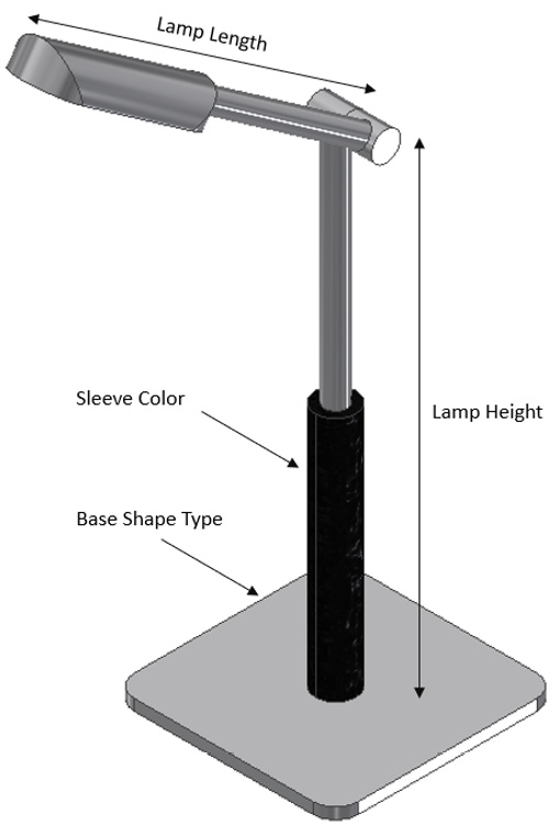
Figure 10.18: Lamp with references to things that will change in the rule to be created in the assembly
Getting ready
To begin this recipe, you will need to navigate to Inventor Cookbook 2023, then select the Chapter 10 folder, followed by the iLogic Lamp folder. Then open iLogic Lamp.iam.
How to do it…
To start the recipe, we will open the model and understand the iLogic rules that have been created and how these influence the model. You will also need to familiarize yourself with the table shown in Figure 10.19, as this details all the configurations of the lamp that our new iLogic rule will control, from the assembly.
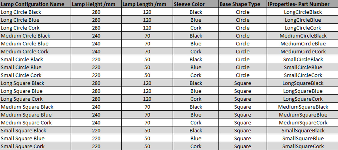
Figure 10.19: Configurations of the lamp that the iLogic rule will generate
Now that we understand all the configuration requirements, we can now start to create the iLogic code to generate these by following these steps:
- Open iLogic Lamp .iam. The assembly consists of three parts. Select the iLogic tab in the Model Browser.
- There are no iLogic rules at this top level of the assembly. Instead, we will need to create a new rule here. First, we will look at each part individually and examine any iLogic rules that are already present. Select the Model tab in the Model Browser.
- Right-click on the lamp:1 part and select Edit. Then select the iLogic tab in the Model Browser. There are three iLogic rules that control this part.

Figure 10.20: Three iLogic rules in lamp:1.ipt
- We will now discess how each iLogic rule functions. Right-click on the BaseType iLogic rule and select Edit Rule.
- Select User Parameters to view the user-defined parameters in the model.

Figure 10.21: Edit Rule window for the BaseType rule open, with User Parameters selected
Looking at the iLogic code, this rule controls the shape of the base of the lamp, by either activating or deactivating an extruded cut that is part of Extrusion5. A conditional If Then, End If statement controls this with a True or False option.
- Select Close.
- Right-click on the SleeveType iLogic rule and select Edit Rule.
- Select User Parameters to view the user-defined parameters in the model.
The SleeveType iLogic rule controls the color of the sleeve that partially covers the vertical stand of the lamp. If the parameter in the model is changed to Black, for example, then the color of the Sleeve is also set to black. There are three options within this rule: Black, Blue, and Cork.
- Select Close.
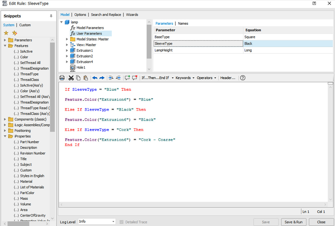
Figure 10.22: Edit Rule for SleeveType open, with User Parameters selected
- Right-click on the LampHeight iLogic rule and select Edit Rule.
- Select User Parameters to view the user-defined parameters in the model.
The LampHeight iLogic rule controls the height of the extrusion, which defines the lamp’s height (the dimension name that controls lamp height is d6) and sets the exact value this must be when either Long, Medium, or Small is selected.
- Select Close.
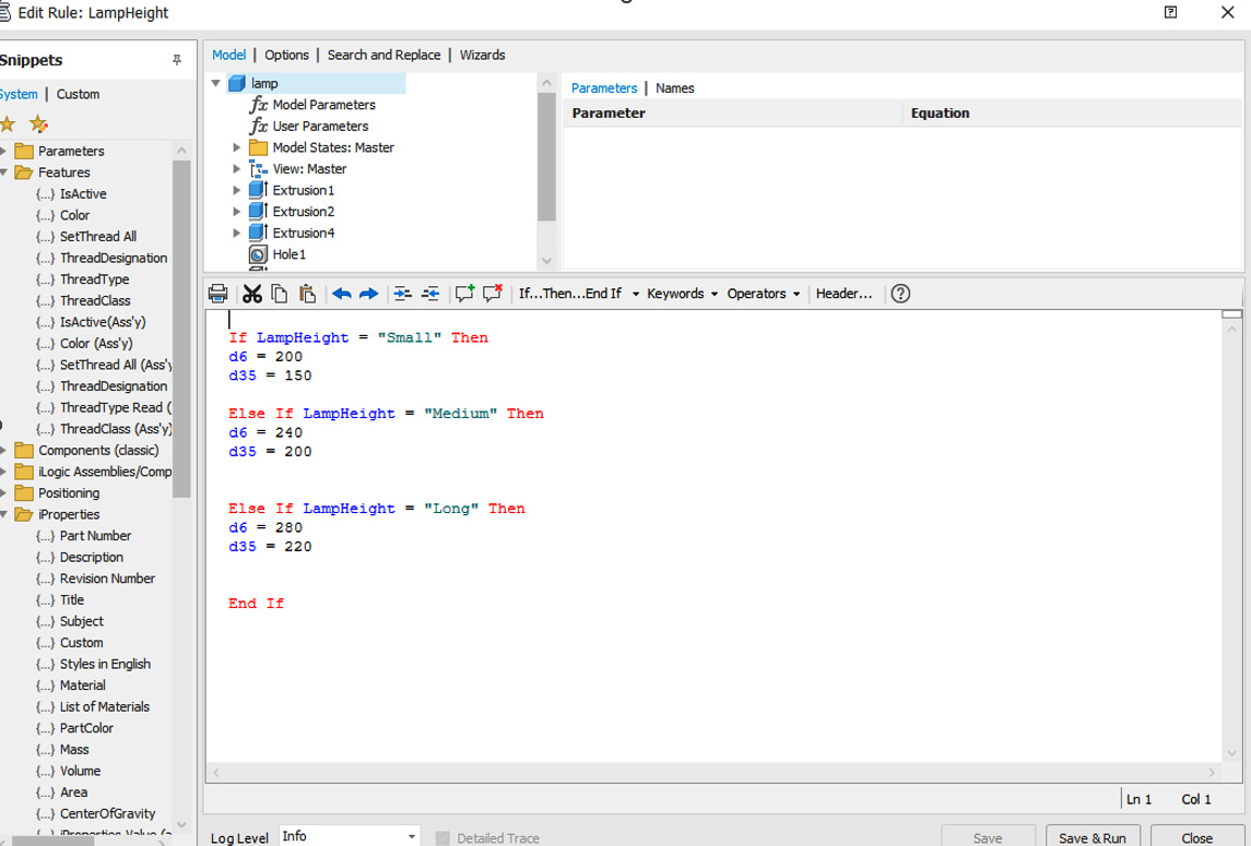
Figure 10.23: Edit Rule window for LampHeight open, with User Parameters selected
- In the ribbon, select Return to return to the assembly.
- Select the Model tab in the Model Browser; right-click on lamp_prt2:1 and select Edit.
- Open the iLogic tab in the Model Browser.
- Right-click on LampLength and select Edit Rule.
- Select User Parameters to view the user-defined parameters in the model.
The LampLength iLogic rule controls the length of the extrusion, which defines the lamp’s length (this is dimension d4) and sets the exact value this must be when either Long, Medium, or Small is selected.
- Select Close.
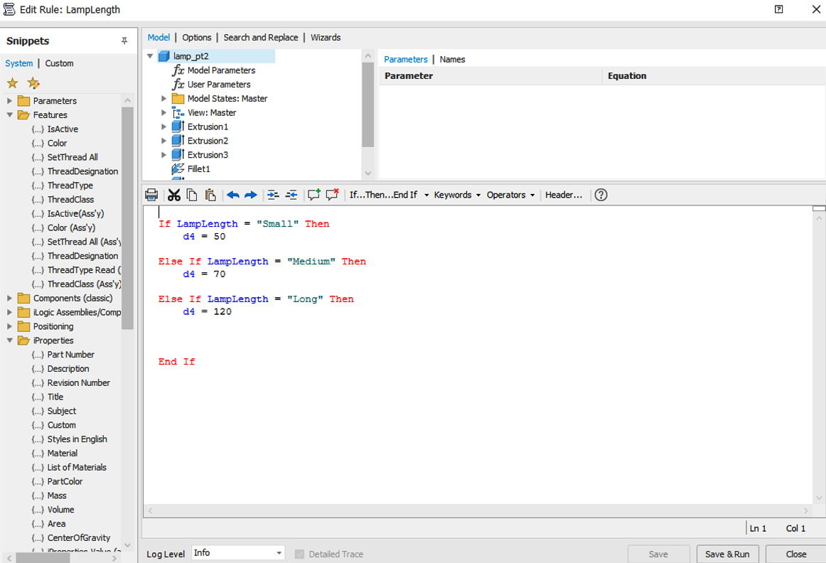
Figure 10.24: Edit Rule window for LampLength open, with User Parameters selected
- In the ribbon, select Return to return to the assembly.
- We now need to create an iLogic rule in the top level of iLogic Lamp.iam, which references all the iLogic rules that are at the part level, so that we can create the configurations outlined in Figure 10.19. Select the Manage tab, then select Parameters.
- In the Parameters window, we will create a user-defined multi-value parameter that will be used to select the configuration by name. The iLogic rule we will create will reference this. Under User Parameters, select Add Text Parameter. Add the name LampConfig to the parameter.
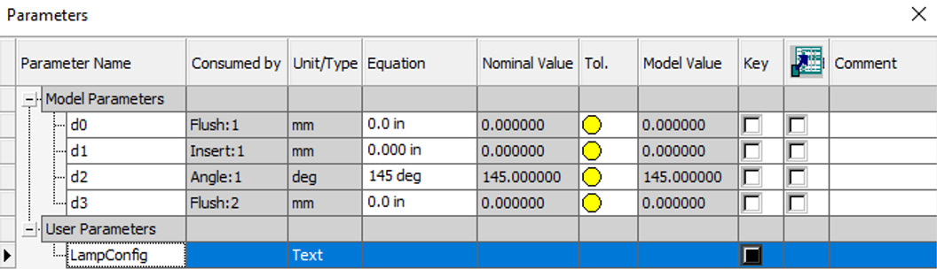
Figure 10.25: LampConfig user parameter created
- Right-click on LampConfig and select Make Multi-Value. In the Value List Editor window, type the following:
Long Circle Black
Long Circle Blue
Long Circle Cork
Medium Circle Black
Medium Circle Blue
Medium Circle Cork
Small Circle Black
Small Circle Blue
Small Circle Cork
Long Square Black
Long Square Blue
Long Square Cork
Medium Square Black
Medium Square Blue
Medium Square Cork
Small Square Black
Small Square Blue
Small Square Cork
- Then select Add, followed by OK. This adds the configuration names into the user parameter dropdown for selection. Now you can click Done.
We now need to write a rule to reference this parameter.
- Select the iLogic tab. Right-click and select Create New Rule. Name the iLogic rule LampConfig and select OK. The Rule Editor window opens.
We now have to write iLogic code for every configuration we wish to generate from the pre-defined user parameter list. We will reference the existing rules at the part level of this assembly.
- Start by typing the following:
If LampConfig = "Long Circle Black" Then
This identifies the rule in our assembly that if Long Circle Black is selected from the dropdown, then... do something.
- We now need to reference a specific existing parameter. Expand lamp:1 in the model tree within the Edit Rule window. Select User Parameters. With your cursor on the next line of code, double-click the LampHeight parameter to import it into your code. Type = "Long" after this snippet.

Figure 10.26: Parameter(“lamp:1”, “LampHeight”) = “Long” added
This rule now states that if LampConfig is set to Long Circle Black, change LampHeight to the value stated in the LampHeight rule, that is, = Long.
- We must now repeat this process for all other aspects of the configuration. Add the following code below Parameter("lamp:1", "LampHeight") = "Long":
Parameter("lamp:1", "SleeveType") = "Black"Parameter("lamp:1", "BaseType") = "Circle"Parameter("lamp_pt2:1", "LampLength") = "Long"iProperties.Value("Project", "Part Number") ="LongCircleBlack"
The result of this is displayed in Figure 10.27.
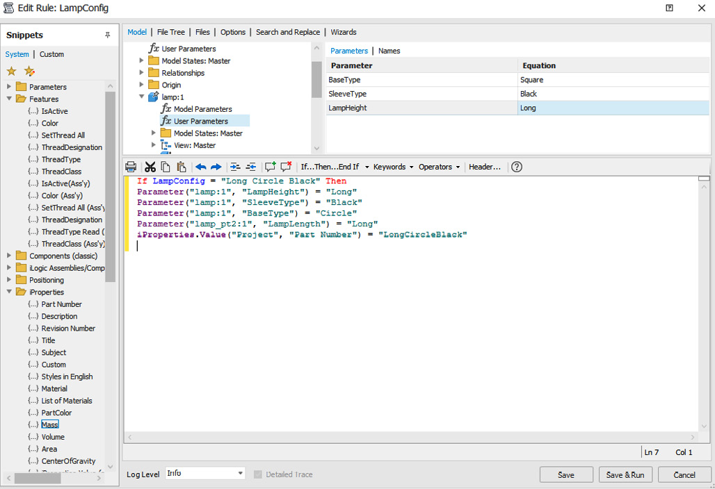
Figure 10.27: Completed code for LampConfig= Long Circle Black
The last line of code added changes Part Number in the iProperties of the assembly to the text shown automatically when the rule runs.
This code must now be duplicated and edited to reflect all the other possible configurations in the LampConfig dropdown.
- The following code needs to now be added below the current paragraph of code shown in Figure 10.27. You can also copy and paste this from iLogic Lamp Code.docx located in the Inventor Cookbook 2023 | Chapter 10 folder.
- Once you have added the code in step 29, select Save & Run.
- Select Parameters and cycle through the LampConfig drop-down options. As you select each configuration, the iLogic rule in the assembly runs and references existing rules in the part files to generate the desired configuration of the lamp automatically.

Figure 10.28: Completed iLogic assembly; LampConfig options selected for ‘Medium Square Cork’
Using iLogic rules defined in the top level of an assembly, you have created a rule that references multiple existing iLogic rules at the part level to produce automatic configurations of a lamp that enable the user to define the base type, height, length, and color, and set automatic part numbers in the iProperties.
Creating an iLogic form and Event Triggers
iLogic forms represent the simplest way for users to generate configurations of models, and they provide an easy-to-use interface to do so. In this recipe, you will create an iLogic form that opens upon the action of an iTrigger. The iLogic form will allow the user to customize a mounting plate, based on predefined iLogic rules and parameters in the model.
Getting ready
To begin this recipe, you will need to navigate to Inventor Cookbook 2023 folder, then select Chapter 10. Select the iLogic Form folder and then Mounting Plate.ipt.
How to do it…
The model has already been created, and there are already two iLogic rules, which are as follows:
- Material Selection allows the material of Mounting Plate.ipt to be set either as steel alloy or as titanium
- Plate Sizing controls the size of the length and width parameters so that only three variants can be picked
You will now start the configuration of an iLogic form to make the configuration of material and plate sizing of this much easier:
- Select the iLogic tab and select Forms.
- Right-click on Forms and select Add Form. Form Editor opens. Here we can define and create a live preview of what the final iLogic form will look like.

Figure 10.29: iLogic Form Editor open
- Under Label, select Form 1 and type a new form name: Mounting Plate Configuration.
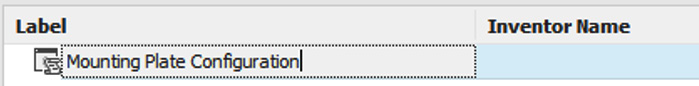
Figure 10.30: Label changed to Mounting Plate Configuration
- From the Toolbox area, click and drag the Picture element over to Form Workspace, as shown in Figure 10.31.
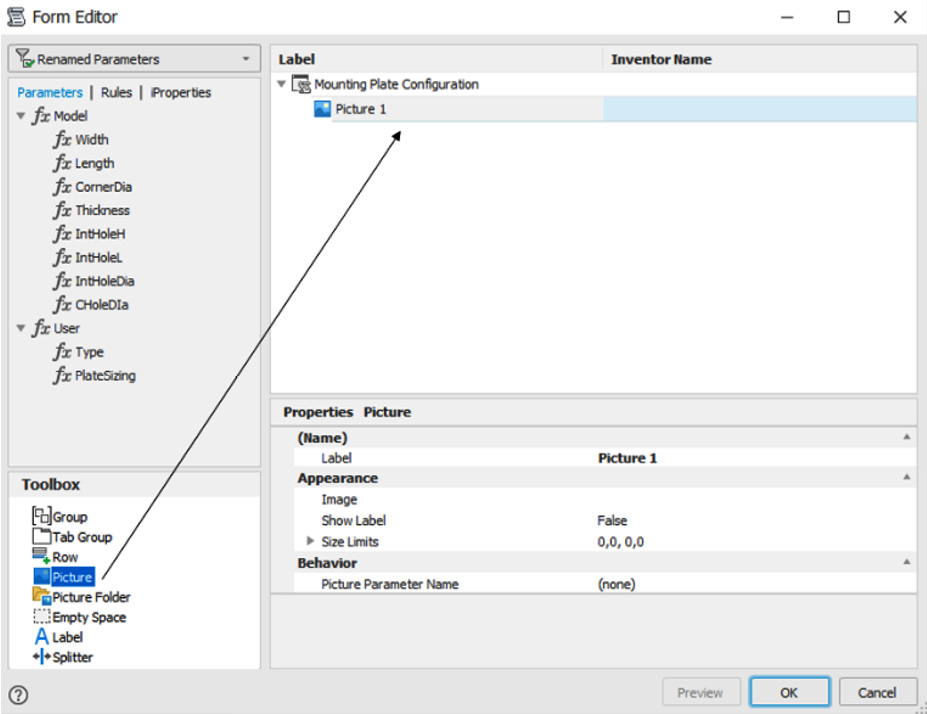
Figure 10.31: Picture element dragged to Form Workspace
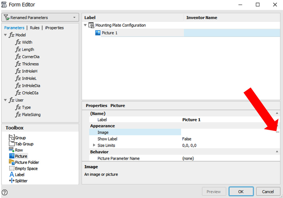
Figure 10.32: The iLogic Form Editor with the Image Browser command show.
- Then browse the Chapter 10 folder, and select Mounting Plate.png. Select Open. The image is incorporated into iLogic Form Preview.

Figure 10.33: Mounting Plate image now incorporated into the iLogic Form Preview
- Now we will start to add functionality so that the mounting plate can be configured in the form. Click and drag three instances of Tab Group from the Toolbox into Form Workspace.
- Rename the Tab Groups as shown in Figure 10.34.
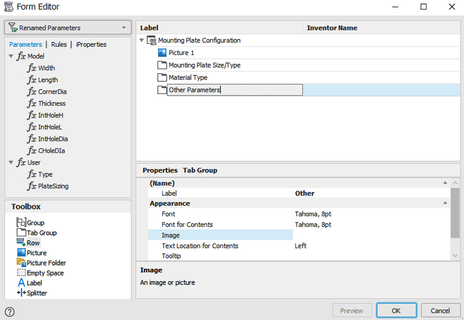
Figure 10.34: Tab Groups added and renamed
- Click and drag the following parameters to the renamed Tab Group folders in Form Editor as shown in Figure 10.35.

Figure 10.35: Parameters dragged into the correct Tab Group folder
The preview of the form will have updated, reflecting these changes.
- We will now make the Inventor names for the parameters more meaningful for the purpose of the form. Select PlateSizing, then type Mounting Plate Type & Sizing under Label, as shown in Figure 10.36.

Figure 10.36: PlateSizing renamed to Mounting Plate Type & Sizing in the iLogic form
Form Preview will automatically update to reflect the change.
- Repeat step 10 with the other parameters:
- Type = Material Selection
- Thickness = Thickness of Plate
- IntHoleDia = Internal Hole Dia
- CholeDia = Central Hole Dia
- Additional buttons will now be added to the form. Select the top level in Form Editor: Mounting Plate Configuration. Scroll down the Properties form to Behavior. Select Done. Under Predefined Buttons, select OK Cancel Apply.
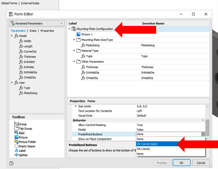
Figure 10.37: OK Cancel Apply selected as additional buttons in the iLogic form
- Select OK to complete the form.
- On the iLogic tab, select Form, and select Mounting Plate Configuration.
- The iLogic form is launched; test the form by editing the drop-down menus and the allowable values. The part file will update automatically.

Figure 10.38: iLogic form launched and tested
- Close the iLogic form. Currently, this iLogic form requires the user to manually open it.
- We will now create an iTrigger to automatically open the form as soon as Mounting Plate.ipt is opened. Select the Manage tab and navigate to the iLogic panel. Select iTrigger.
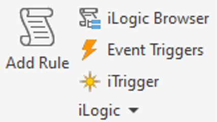
Figure 10.39: iLogic iTrigger command
- Select Parameters. An iTrigger0 user parameter has been created in step 17. Select Done.
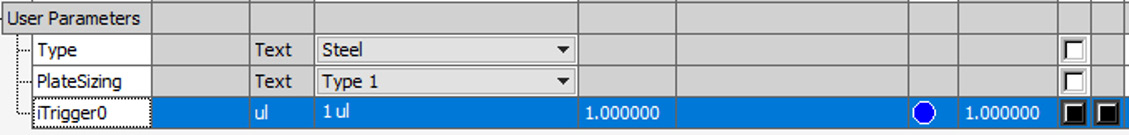
Figure 10.40: iTrigger0 added to User Parameters
- Close Parameters. Navigate to the Manage tab, and in the iLogic panel, select Add Rule.
- Name the rule iLogic Form Launch. Select OK.
- Next, type trigger=iTrigger0 as the first line of code. Then navigate to the Forms folder in the Snippets area and double-click Show Form. Then adjust the code so that Mounting Plate Configuration is entered as the specific form to show. This will launch the form automatically as the document is opened. Select Save & Run. Close the form.

Figure 10.41: Adding code for the iTrigger
- Now we will create an Event Trigger to execute a rule automatically. This will be performed on the Material Selection rule so that if the material is manually changed in the model by the user, it will revert to the only choices available in the form: steel alloy or titanium. In the Manage tab, find the iLogic panel and select Event Triggers.
- Click and drag the Material Selection rule into the Material Change event category.

Figure 10.42: Material Selection rule added to Material Change Event Trigger
- Select OK. If the material is changed in the Material Editor and not the iLogic form, the material will revert to steel alloy automatically as the Event Trigger is triggered and runs the Material Selection rule.
You have created an iLogic form with multiple functions and rules that enables the configuration of a mounting plate part. iTriggers have been set to launch the form upon the document opening, and Event Triggers have been configured to maintain the correct material selection.
Model credits
The model credits for this chapter are as follows:
- iLOGIC CAT LADDER (by Jacobus Willlemse): https://grabcad.com/library/ilogic-cat-ladder-1
- Modern Lamp (by Kyle Canalichio): https://grabcad.com/library/modern-lamp-1