
4
Freeform, Surface Modeling, and Analysis
Surfaces in Inventor are non-solid, zero-thickness features that define contoured shapes and geometry. They are often used to depict complex forms where traditional solid modeling tools would be limited in communicating the design intent. Surfaces can be used in context with solid modeling techniques or independently. Surfaces in Inventor can also be used as references to aid in the creation of other geometry in the model. In most cases, surfaces in Inventor are used to create surface models that are converted to solid models, define complex curves, cuts, and extrusions, or create a skin over imported wireframe models. The Freeform modeling tools within Inventor allow you to create complex organic shaped forms with conventional modeling techniques.
Both surface modeling and freeform geometry modeling environments and tools will be covered in this chapter. We will examine the limitations of the conventional lofts and sweeps within Inventor. It is important to understand the use of these conventional tools so that you will be better placed to decide when to employ a freeform or surface modeling strategy. Then, we will explore surface modeling and freeform geometry modeling environments and tools.
In this chapter, you will learn about the following:
- Creating area lofts
- Creating path and guide rail sweeps
- Creating solid geometry from basic extruded and lofted surfaces
- Creating 3D sketches for surfacing and applying the Trim, Combine, Thicken, and Ruled Surface commands
- Learning how to trim, patch, and convert surfaces to solids with Sculpt
- Replacing a solid face with a surface
- Using the Copy Object command to create a matching contoured part to another part
- Importing surfaces into Inventor
- Validating surface designs: Zebra Analysis, Surface Analysis, and Curvature tools
- Understanding the basic features and techniques of freeform modeling
- Freeform modeling within the context of existing geometry
Technical requirements
To complete this chapter, you will need access to the practice files in the Chapter 4 folder within the Autodesk Inventor 2023 Cookbook folder.
Creating area lofts
An area loft enables you to create geometry by blending multiple profiles; they are similar to rail and centerline lofts, except with an area loft, you can define the area of each section at specific points along its path or centerline.
In this recipe, you will use an Area Loft operation to create the base geometry of a glass. The sketches and planes have already been created for you.
Getting ready
Open Glass.ipt file from the Chapter 4 folder.
How to do it…
In this example, we will use Area Loft to create the geometry of a glass. This will involve using the standard Loft command and selecting the Area Loft options. To do this, see the following:
- With the Glass.ipt file open in Inventor, navigate to the 3D Model tab and select the Loft command.
- The Loft command window now opens. From here you can create a range of different lofts but in this example, we will use the Area Loft function to create the geometry of this glass from the simple sketches provided. So, select the Area Loft option in the Loft command window, as shown in Figure 4.1:
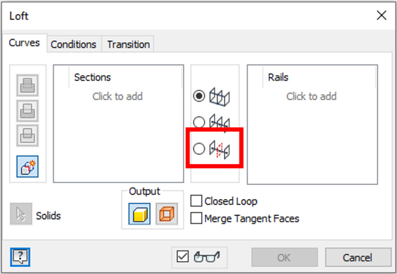
Figure 4.1: Area loft selected within the Loft command window
- Select Click to add in the Sections box and proceed to select the two circle sketches. A preview will now be shown of the base loft as per Figure 4.2:
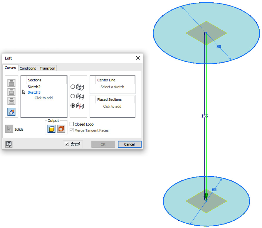
Figure 4.2: Preview of the area loft shown
At this point, the Loft command is still creating a normal loft. To start to use the area functionality, we now need to select and define the centerline, and specific points to incorporate different areas or profiles of the loft.
- Select Center Line in the window and then select the centerline between the two circles in the graphics window. The preview will update and show a basic loft as per Figure 4.3:
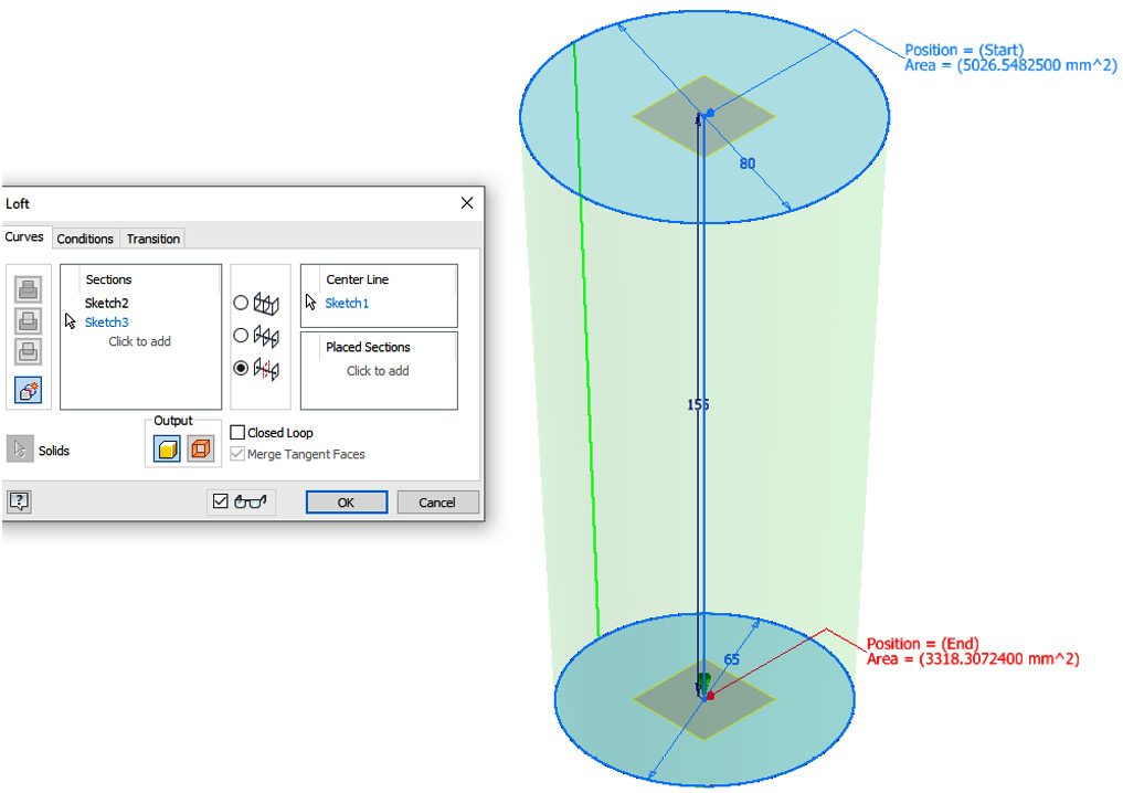
Figure 4.3: Preview of the area loft shown
- Now that the profiles and centerlines have been defined, we can specify points along the centerline to create different areas for the area loft. Select Placed Sections and select a point along the centerline as per Figure 4.4:
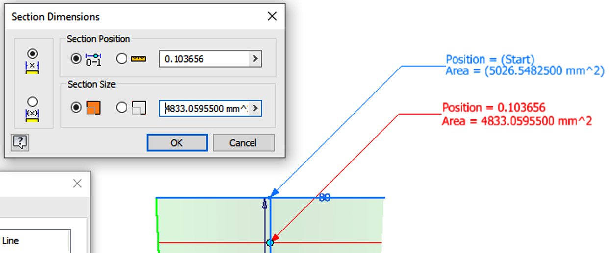
Figure 4.4: The placement of the first placed section
Inventor has now opened another window for us to define the position of the point along the centerline and the section size. The values that need to be entered are as follows:
- Position: 0.15
- Section size: 6000 mm^2
Then, select OK.
As you enter these values, the shape of the area loft will change.
- Now, repeat the process in step 5, adding the positions and section sizes as detailed in Figure 4.5:

Figure 4.5: Position and area values to create
- Once all Position and Area values have been defined, select OK to complete the area loft. With one simple operation of using the area loft and a simple sketch, you have created the basic geometry of a glass.
This is a very effective and easy way to create complex curvature, without using surface modeling or freeform modeling. The operation can also be made as a cut, intersection, or outputted as a surface if required.
- Now, select the Shell command from the 3D Model tab.
- Select the top face of the glass to remove in the shell operation and define the thickness in the Shell command window as 2mm. This is shown in Figure 4.6. Select OK to complete the operation:
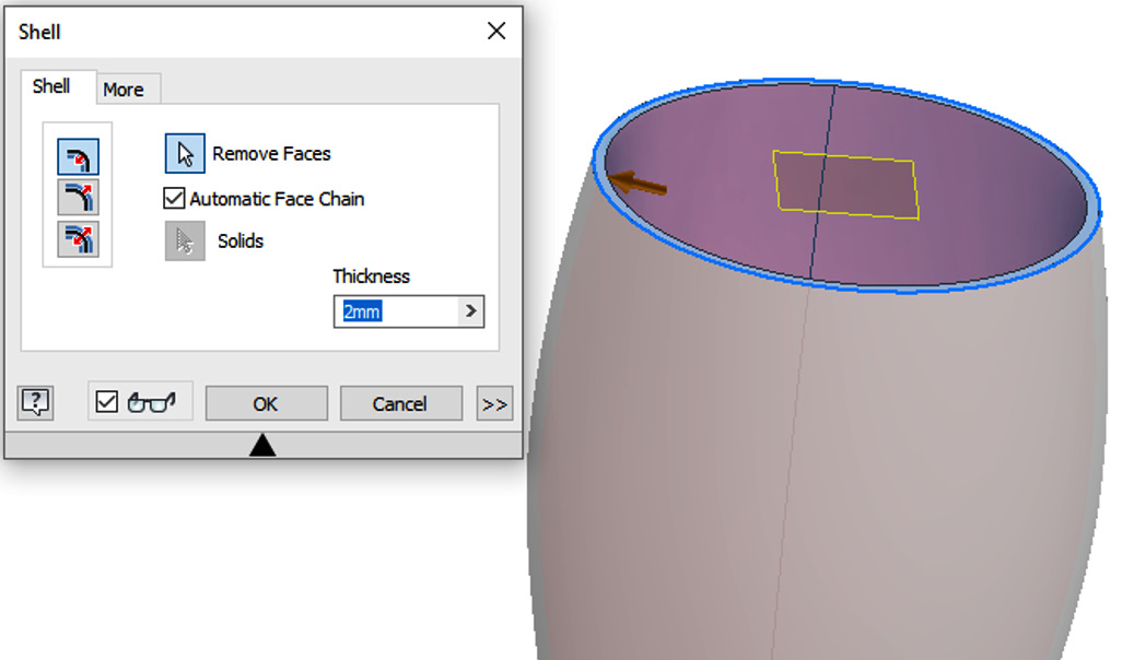
Figure 4.6: Shell thickness and face to remove from model
- Select the Fillet command and apply a 2mm fillet on the two edges, shown in Figure 4.7:
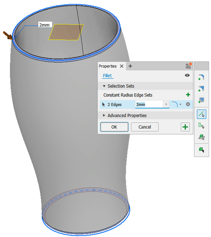
Figure 4.7: 2 mm fillets added to the glass
- Finally, right-click on Glass in the Model Browser. Select iProperties | Physical | Material and then select Glass from the drop-down menu. Select Apply, followed by OK. All Inventor files contain iProperties, which are used to manage files, and automatically update linked information such as BOMs, drawing parts lists, and title blocks. iProperties also contain information about the part, such as mass and material.
You have now used the Area Loft command to generate the complex geometry of a glass.
Creating path and guide rail sweeps
Sweeps can be created as cuts, joins, intersections or to create new solids. They are used to sweep a profile along a defined path. Either the addition of a guide rail or a surface can be used to further control the output.
In this recipe, you will use the Path & Guide Rail function of the Sweep command to generate and complete an ergonomic handle of a kettle and apply a swept groove into the body of the kettle. The outcome of this is shown in Figure 4.8:

Figure 4.8: The completed Kettle.ipt model
Getting ready
Open Kettle.ipt from the Chapter 4 folder.
How to do it…
To start with, we will examine the model and then start to utilize the existing sketches provided, to create the cuts. To do this, let’s see the following:
- With the Kettle.ipt file open in Inventor, select Sketch24 from the Model Browser. This highlights the sketch. A spline about the centerline of the curved handle will be shown in the graphics window.
Sketch 24 is what has been created to act as the path for the sweep operation. Navigate to the Create tab and select Sweep.
- In the Sweep window, do the following:
- Select Profile and proceed to pick the circle profile of the curve.
- Select Path and then set Spline to be the Curve/Path option.
- Select Follow Path as the Orientation option.
- Select Intersect as the Boolean option.
These options are shown in Figure 4.9:
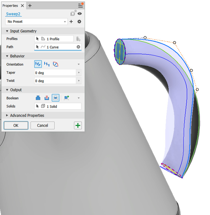
Figure 4.9: Sweep preview for the handle
- Select OK to complete the sweep. The sweep is generated and the handle is intersected with the sweep to create a more ergonomic design.
- The ends of the handle need to be defined and joined or blended to the profile of the kettle housing. Select Start 2D Sketch and create a new sketch on the flat circular face shown in Figure 4.10. For the sketch, select Project Geometry and then select the face:

Figure 4.10: Face to create a new sketch and project geometry
- Select Extrude and then select the newly created projected sketch as the profile. Set Distance in the menu to the To option and select the surface of the kettle. The preview should resemble Figure 4.11 with the extrusion blending into the body of the kettle:
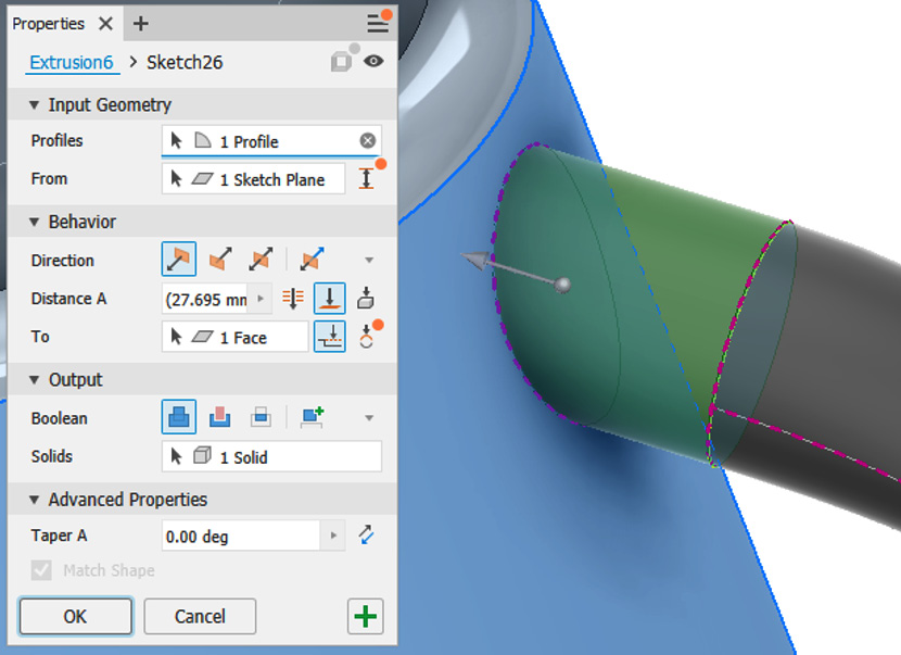
Figure 4.11: Extrusion to create that completes the top of the handle
- Select OK to complete.
- Repeat the projected sketch and extrusion. Remember to define the extrusion as To for the bottom of the handle; the result of this is shown in Figure 4.12:

Figure 4.12: The completed handle on the kettle
You have now completed the handle of the kettle.
We will now create a cut sweep along a path with a guide rail and reference surface to create an aesthetic detail on the kettle housing. The base sketches and planes have already been defined for you in the assembly.
A surface that intersects the model has already been created, following a spline of how we want the detail to be defined. This has then been projected onto the curved surface using the 3D Intersection Curve sketch tool. Near the top of the handle, a circle has been drawn to define the profile of the cut on a plane created at the end of the intersection.
- Select Sweep and navigate to the top of the handle. Locate 5mm Diameter Circle and select this as the profile for the sweep operation. This is shown in Figure 4.13:

Figure 4.13: Profile to select for the second sweep operation
- Select Curve in the Sweep menu, and then select the projected intersection curve on the housing. It is displayed in yellow by default. Figure 4.14 shows this selected:

Figure 4.14: Intersection curve selected to form the path of the sweep
- For Orientation, select Guide.
- Select the cylindrical face of the kettle as the given Reference Surface, illustrated in Figure 4.15:
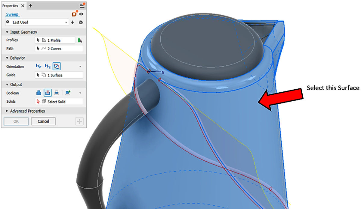
Figure 4.15: Surface to select
- Boolean should default to Cut; if it’s not, select Cut.
- Select Solid in the window and then navigate to the Model Browser and select Solid1 from the Solid Bodies folder, as per Figure 4.16:

Figure 4.16: Selection of Solid1 for the sweep operation
You have completed the kettle, by using advanced sweep functionality, including sweeping along a path, sweeping along a path with a guide rail, and sweeping along a path and guide surface.
Creating solid geometry from basic extruded and lofted surfaces
With this recipe, you will complete the modeling of an EV charger using basic surface tools. You will learn how to create a basic extruded surface for use as a termination point for an extrude and how to create and apply a lofted surface, which transitions between two edges on different surfaces. The resultant surfaces will then be combined with a stitch operation and converted to solid geometry.
The completed model of the EV charger you will create is shown in Figure 4.17:

Figure 4.17: Completed EV charger model
Getting ready
You will need to access the EV Charger.ipt file in the EV Charger folder within the Chapter 4 folder.
How to do it…
The EV charger model is partially created and you do not have to build this from scratch. We will be applying surface modeling techniques to complete the model. To do this, let’s see the following:
- Open EV Charger.ipt. The unconsumed sketches required have been left visible and are shown in black and yellow on the model.
- The first objective is to create the curved geometry in the center of the EV charger where there is currently a large opening, shown in Figure 4.18. We will extrude Sketch 2 as a surface and select the Extrude command:

Figure 4.18: The EV charger model with the opening we will complete using surface modeling
- In the Extrude command, navigate to the top right of the window and select the Surface Mode ON button as per Figure 4.19. This changes the Extrude command to extrude a surface instead of a solid geometry:

Figure 4.19: Surface mode on selected in the Extrusion window
- In the Profiles section of the window, deselect Profile1 if this is selected by default; do this by clicking the x symbol next to Profile1. Then, select Profile and pick the sketched spline as shown in Figure 4.20:

Figure 4.20: Selection of the sketch spline to create the surface to extrude from
- In the Behavior section of the command window, under Direction, flip the direction of the extrusion by selecting the Flipped icon, as shown in Figure 4.21:
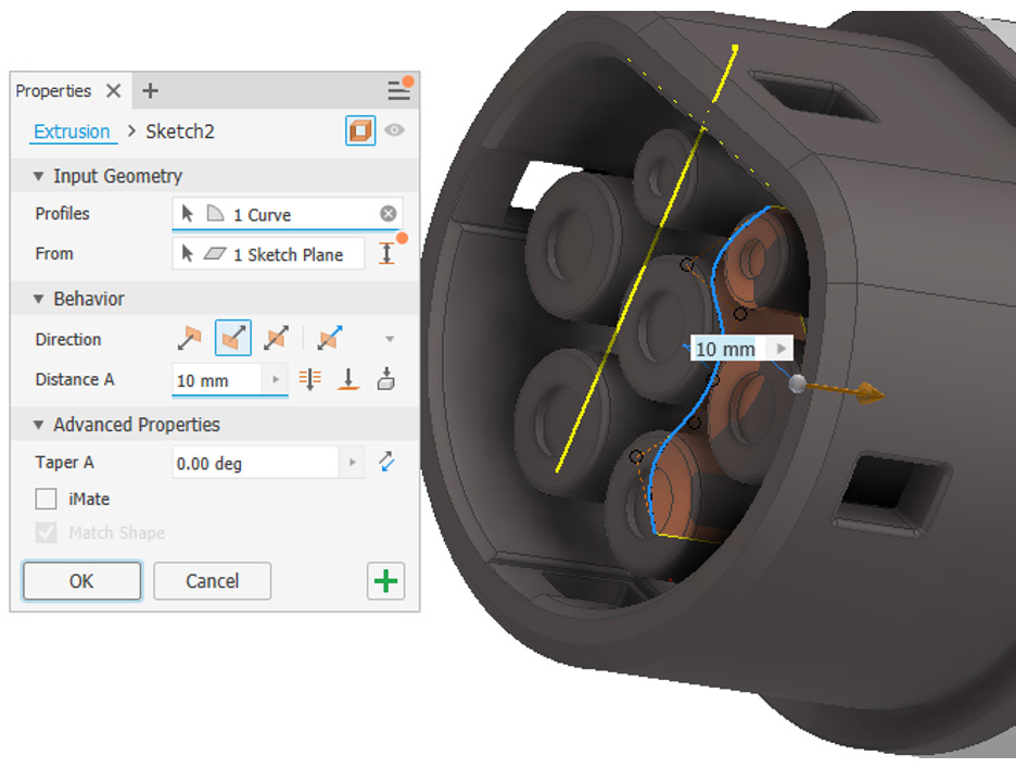
Figure 4.21: Direction of the surface extrusion flipped
- Extend the Distance value by clicking and dragging the orange display arrow. Extend this to around 150 mm. The preview should display as per Figure 4.22 once complete:

Figure 4.22: Completed preview of surface extrusion
- Select OK to complete the Surface Extrude operation.
- Select the Extrude command again to start the creation of a new extrusion.
- Select Surface Mode OFF in the top right of the command window if this is still active from the previous extrusion.
- For Profile, select Sketch 1, which is the projected sketch in the center of the opening of the EV charger, as shown in Figure 4.23:
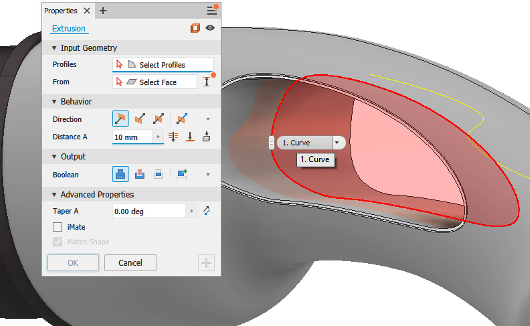
Figure 4.23: Profile to select for the extrusion
- Select To for Distance and select the face of the extruded surface you previously created. The preview will look like Figure 4.24:
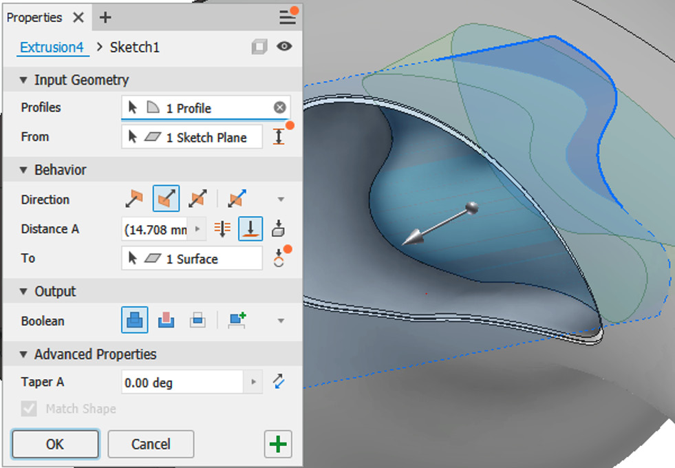
Figure 4.24: Preview of the extrusion after the profile and the surface have been created
- Select OK.
This completes the operation. You have now successfully used a basic extruded surface for use as a termination point to create the desired geometry.
This geometry needs to be replicated on the other side of the model.
- Navigate to the other side of the opening in the graphics window and select Mirror from the Pattern commands.
- Select the solid extrusion created by step 12 as the feature to mirror.
- Select Mirror Plane in the Mirror window and then select the surface shown in Figure 4.25:
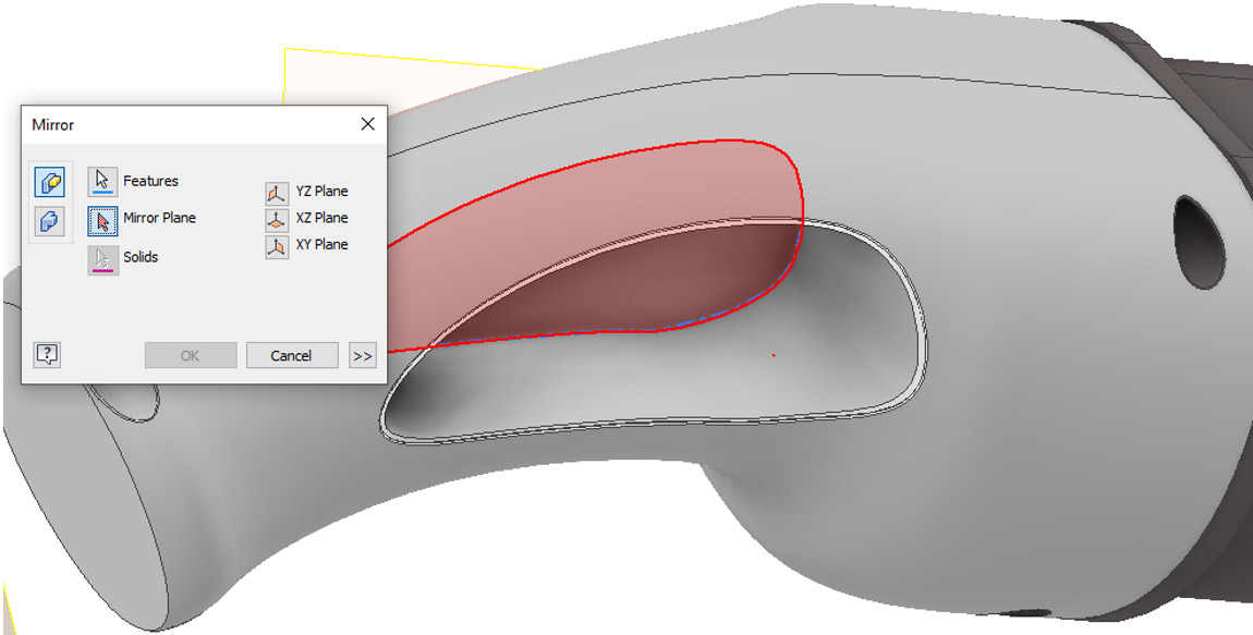
Figure 4.25: Showing the mirror plane to select
- Select OK to complete.
- Navigate to the Model Browser, right-click ExtrusionSf#, and then select Visibility. This removes the visibility of the surface extrusion, as it is no longer required.
- Use Start 2D Sketch on XY Plane.
- Select Project Geometry and then select Work Plane 1.
- Create the sketch as shown in Figure 4.26:
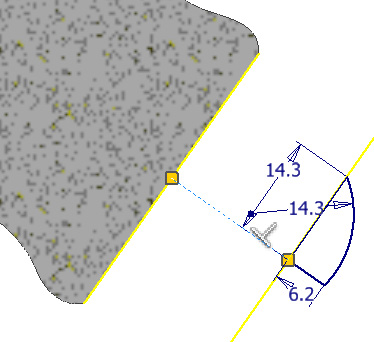
Figure 4.26: Sketch to be created on the XY plane
- Select Finish Sketch and then select Revolve.
- Select Surface Mode ON.
- Select the recently created sketch from step 20 as the profile.
- Select the line that is 6.2 mm long as the axis. The preview generated is shown in Figure 4.27:
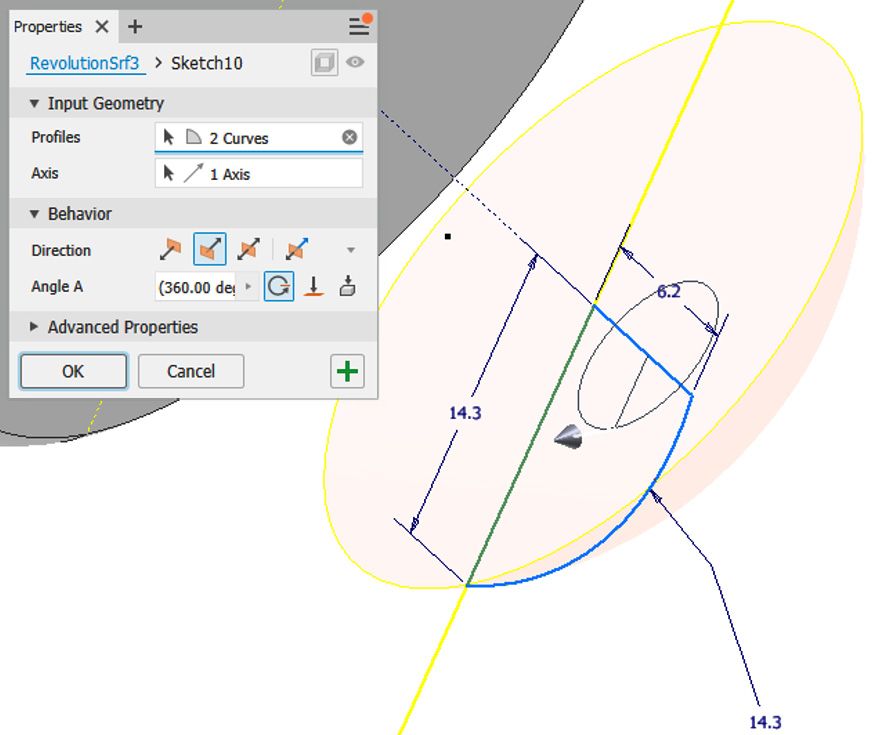
Figure 4.27: The preview of the extruded revolving surface
- Select OK to complete the revolve as a surface.
- Navigate to the Model Browser, right-click Work Plane 1, and then select Visibility.
- Select Loft from the Create tab. Select Output as Surface.
- Click Sections and then Click to Add. Select the sketch lines shown in Figure 4.28:

Figure 4.28: Sketch sections to select
- Select OK to complete the lofted surface.
- We now need to stitch and combine the two surfaces, so that they form a quilt or composite surface. Select Stitch from the Surface tools.
- Change Maximum Tolerance to 0.2 mm and select the two surfaces to stitch together.
- Select Apply and then Done to complete the stitch operation.
- Now, we can convert the quilted surface into solid geometry. Select the Thicken/Offset command from the Modify panel.
- Select the two faces as shown in Figure 4.29. Change Thickness Distance to 4 mm.
- Select OK:
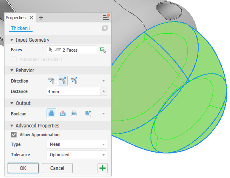
Figure 4.29: Thicken/Offset command with faces selected and thickness distance defined
- Use Start 2D Sketch on Work Plane 1.
- Then, create the following sketch on Work Plane 1 as shown in Figure 4.30. The internal circle needs to be 15 mm in diameter:

Figure 4.30: Sketch to create on Work Plane 1
- Select Finish Sketch.
- Select Extrude.
- Select the sketch previously created as the profile, change Direction to Symmetric, change Distance to 50 mm, and change Boolean to Cut. The preview is shown in Figure 4.31:

Figure 4.31: Extrusion settings to apply
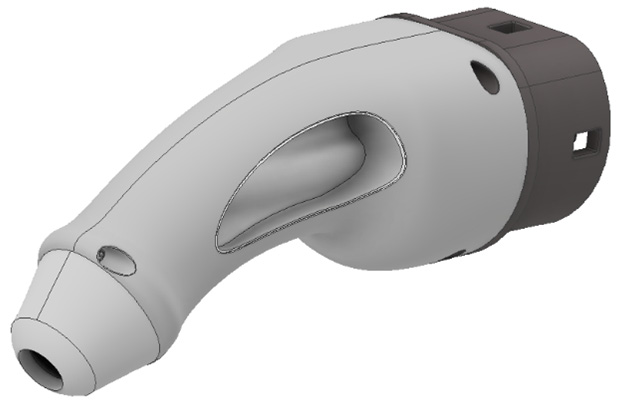
Figure 4.32: Completed EV charger
You have successfully completed the EV charger using basic surface tools such as Extruded Surface, Lofted Surface, and Stitch.
Creating 3D Sketches for Surfacing and applying the Trim, Combine, Thicken, and Ruled Surface commands
In this recipe, you will use a range of 3D surface tools to create an exhaust manifold. Initially, 3D sketches will be created to act as guides for the surfaces to follow. You will then perform surface sweeps and refine these with the Trim, Combine, Thicken, and Ruled Surface commands.
Getting ready
To begin this recipe, you will need to open the Exhaust_Manifold START.ipt file from the Chapter 4 folder.
How to do it
To begin, we will have to create 3D sketches to form the basis of the 3D surface sweeps. We will then use these to perform surface sweeps, apply a thickness, and edit as desired to create the manifold. So, to do this, see the following:
- Look at the existing model of Exhaust_Manifold START.ipt in the graphics window.
You can see that already a base unconsumed sketch of a circle has been created, and the ends of the manifold have already been detailed. The first task is to create the swept geometry of the manifold, using assorted surface tools available. To create the swept surfaces of the manifold, we will need to construct a 3D sketch to act as a guide curve.
Under Start 2D Sketch, open the dropdown and click 3D Sketch, as shown in Figure 4.33:

Figure 4.33: Location of the 3D Sketch tools
- With the 3D Sketch tools active, the ribbon will change and show the 3D sketch commands. Select Line.
- Hover the cursor over the circle in the manifold as shown in Figure 4.34 and, once the green midpoint is visible, left-click to start the sketch:
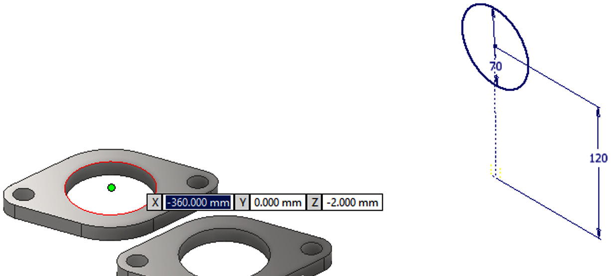
Figure 4.34: Circle on manifold selected and midpoint active
- Create a 3D sketch line in the Z-axis. Type 112mm and hit Enter. The 3D sketch line is created as per Figure 4.35:

Figure 4.35: 112 mm L 3D Sketch line to create
- Select Line again from the 3D Sketch tools and create the line shown in Figure 4.36. The length must be 65mm and in the direction of Y.
- Create another 3D sketch line that joins the two previous lines together, as per Figure 4.36. Select the previous endpoint that was created in step 5 to complete this:
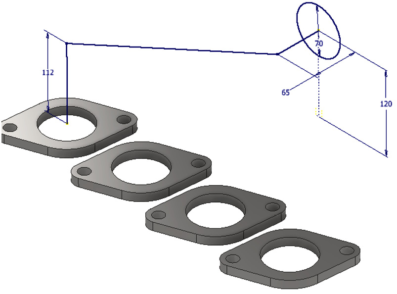
Figure 4.36: Additional 3D sketch lines to create
- Select Bend from the 3D Sketch tools.
- Type 80mm for the Bend Radius option.
- Select both the 112 mm line and the last interconnecting line created.
- Change the value in the Bend window to 65mm.
- Select the 65 mm L line and the middle connecting line to apply the 65 mm bend to the 3D sketch. The result is shown in Figure 4.37:

Figure 4.37: Bends to be created on the 3D sketch lines
- Select Finish Sketch.
- This defined 3D sketch line will form the basis for the surface sweep that will create the first of the exhausts for the manifold. Select the Sweep command from the 3D Model tab.
- Ensure that the option for Surface Mode is turned on for the Sweep command.
- Select the 70 mm circle as the profile and the 3D sketch spline as the centerline for the sweep or (path). The preview will resemble Figure 4.38:
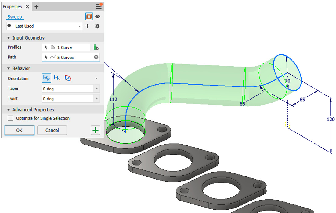
Figure 4.38: Surface Sweep options required to create the first exhaust of the manifold
- Select OK to complete. You have now created a surface that uses a 3D sketch as a reference. The basis of the first exhaust is complete.
- The surface has been created but may not be very visible. Right-click on SweepSrf1 in the Model Browser and then select Translucent. This makes the surfaces much easier to see on a white background.
- We must now define the path for the second sweep for the second exhaust. The process is very similar to the first exhaust, except there are slightly different dimensional values in this case. Select Start 3D Sketch.
- Create a 3D sketch line from the second manifold that is 112mm in length and in the direction of the Z axis. This is shown in Figure 4.39.
- Create a 150mm 3D sketch line from the 70 mm diameter circle in the Y axis, shown in Figure 4.39:

Figure 4.39: 3D sketch lines to create for the second exhaust
- Create a final 3D sketch line that joins the two lines previously created.
- Select the Bend command. Apply a 50mm bend to the corner point of the sketch path, as shown in Figure 4.40:
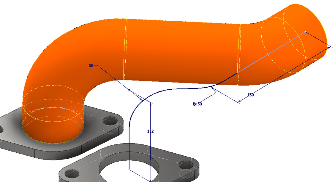
Figure 4.40: 50 mm bends to be created in the 3D sketch path
- Use Start 2D Sketch on Work Plane 1.
- Select Project Geometry from the 3D Sketch tab and select the edge of the surface to project the surface geometry, as shown in Figure 4.41:
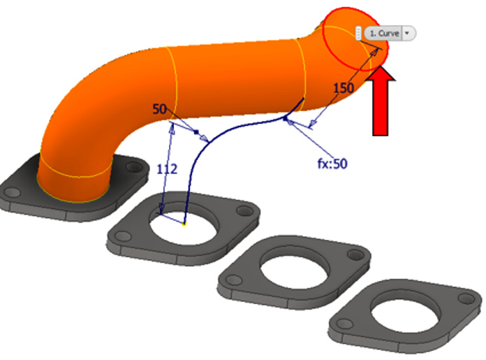
Figure 4.41: Project Geometry used to project the surface of the surface sweep
- Select Finish Sketch. Then, select Sweep.
- With Surface Mode ON selected, set the circle as the profile, and the unconsumed 3D sketch as the path, shown in Figure 4.42.
- Select OK to complete the surface sweep:
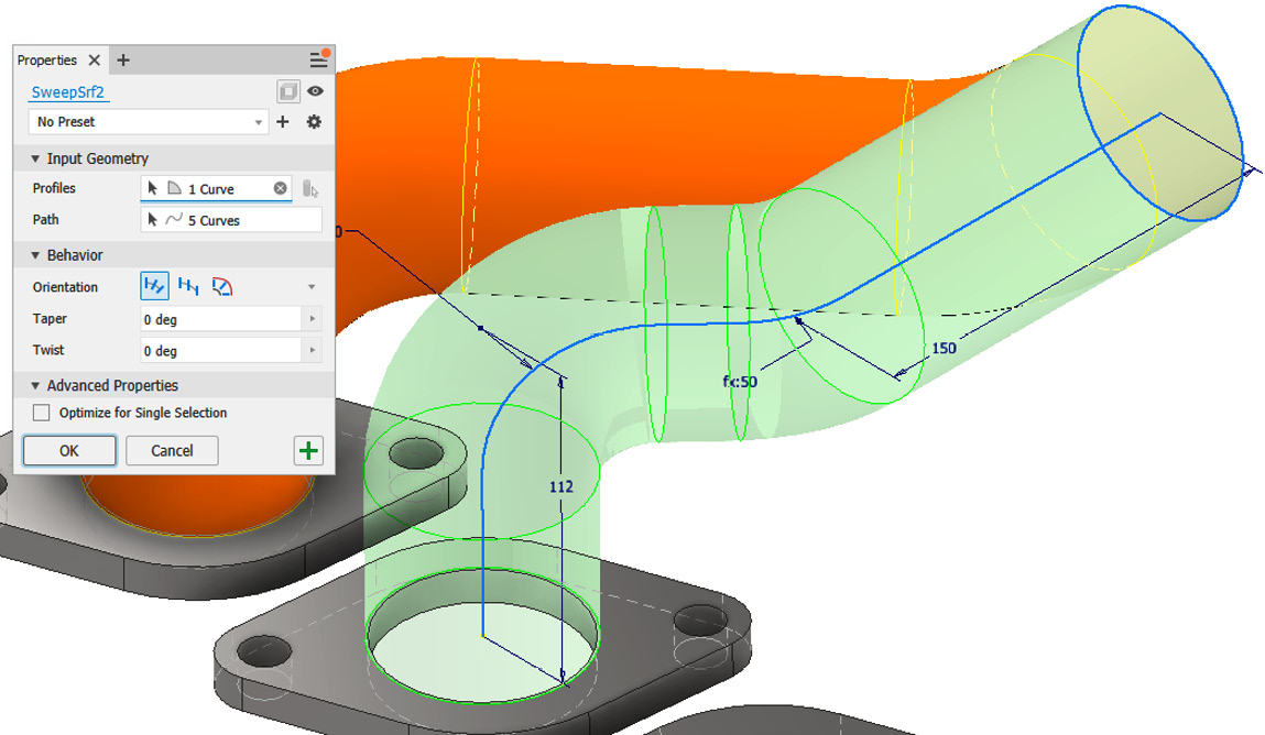
Figure 4.42: Second surface sweep operation to complete
- We will now perform a half-section view to examine the sweep path created. Select the View tab.
- In the Visibility panel on the far left, select Half Section View, and then select the XY plane from the Model Browser.
- Drag the section view by left-clicking and holding the orange arrow, then moving the mouse upward. Do this until the section view resembles Figure 4.43:

Figure 4.43: Creating the section view until the model resembles this
Additional unwanted surface geometry has been created internally because of doing two surface sweeps that intersect. This needs to be cleared out with a Trim Surface operation.
- Select the 3D Model tab, navigate to the right of the ribbon, and in the Surface tools, select Trim.
- You are now able to specify the Cutting Tool settings and the piece of geometry to use the Remove operation on. Select the first sweep created as the cutting tool and select the internal unwanted geometry to remove it. The preview is shown in Figure 4.44:
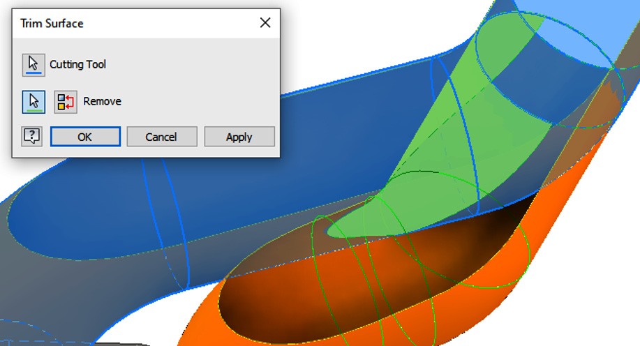
Figure 4.44: Trim Surface cutting tool and removal surfaces shown
- Select Apply to complete the trim. The internal geometry is now removed.
- Repeat this Trim Surface operation once more for the other internal geometry, until the surfaces resemble those in Figure 4.45:
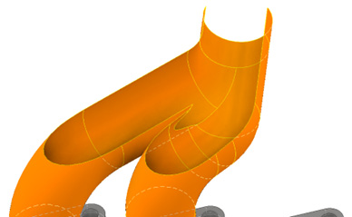
Figure 4.45: The result of two Trim Surface operations to remove the internal unwanted surfaces
- Use Start 2D Sketch on Work Plane 1.
- Sketch the geometry shown in Figure 4.46 on Work Plane 1. Use Project Geometry and, when complete, select Finish Sketch:
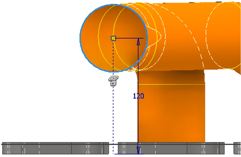
Figure 4.46: Geometry to create on Work Plane 1
- Select Start 3D Sketch and create the line as shown in Figure 4.47, from the 120mm sketch line endpoint. Then, select Finish Sketch:

Figure 4.47: 3D sketch line to create from the 120 mm sketch line
- Using these sketch lines, we will now create a three-point plane to act as a mirror plane, which will enable us to copy the two existing surfaces onto the remaining manifold plates. In the 3D Model tab, select Plane, and then the three-point plane.
- Select the three points on the sketch lines, as shown in Figure 4.48, to complete the plane:
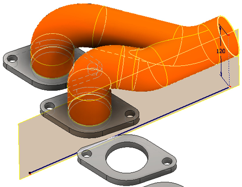
Figure 4.48: Three-point plane to be created from the sketch lines
- With the 3D Model tab active, navigate to the right of the ribbon and select Mirror.
- Select the two surface sweeps as the features to mirror and the newly created Work Plane 2 as the Mirror Plane. Select OK to complete.
Right-click the new mirrored surface features in the Model Browser and select Translucency, to make the surfaces more visible. The result is shown in Figure 4.49:
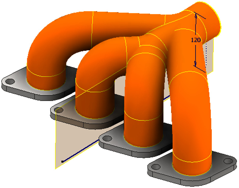
Figure 4.49: Mirror operation of the existing swept surfaces completed
- The basis of the exhausts for the manifold has now been completed. During the Mirror operation, some unwanted internal geometry has been created, which we will now remove. Create a half-section view of the model as per Figure 4.50:
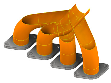
Figure 4.50: Half-section view of the manifold showing unwanted internal surfaces
- Select the 3D Model tab and then select the Trim Surface command:
- Select the Cutting Tool and Remove references shown in Figure 4.51 as the first Trim Surface operation and select Apply:
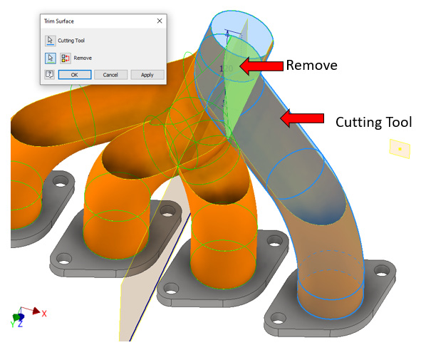
Figure 4.51: Trim Surface operation 1
- For the next Trim Surface operation, select the Cutting Tool and Remove references as per Figure 4.52. Then, select OK:

Figure 4.52: Trim Surface operation 2
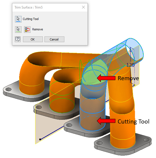
Figure 4.53: Trim Surface operation 3

Figure 4.54: Trim Surface operation 4
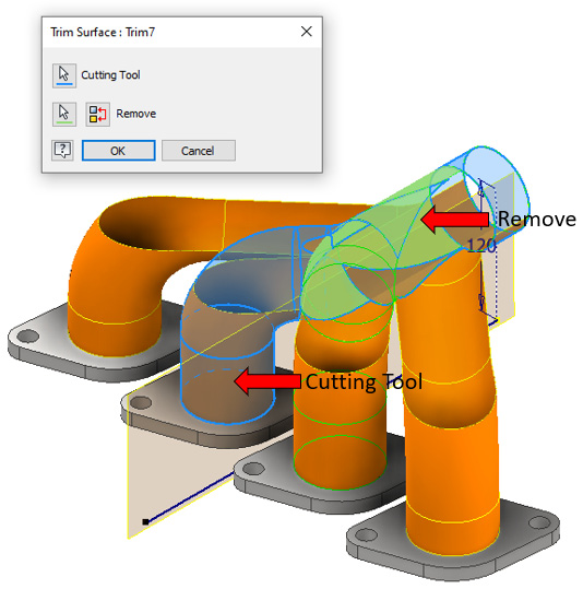
Figure 4.55: Trim operation 5
Figure 4.56 shows the completed result after all the successive Trim Surface operations. All unwanted internal surface geometry has been removed:
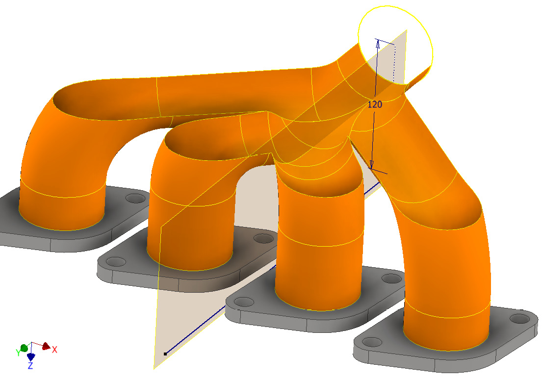
Figure 4.56: Completed surface of the manifold
- The successive trim operations have removed all the internal surfaces so that the manifold is correct. Now, select the View tab, followed by End Section View.
- Next, the multiple surfaces must be combined using a Stitch command. Select the 3D Model tab and navigate to the Surface Modelling tools. Select Stitch.
- With the Stitch command active, select all four exhaust surfaces and select Apply. The surfaces are stitched together as a composite surface. In doing this, the translucency will become active again, as this is a new surface now. Figure 4.57 shows this:

Figure 4.57: Surfaces stitched
- Right-click on Stitch Surface 1 in the Model Browser. Select Translucent to make this more visible.
- Now that a surface is fully defined, we can begin to use the Thicken command to convert the surface to a solid body. To do this, in the 3D Model tab, under the Modify panel, select Thicken/Offset.
This command is used to thicken or offset geometry and works for surfaces too. We will use this to add a specific thickness of material onto the surfaces we have just created. With the Thicken command active, it prompts you to select surfaces or faces to add material. We could select all the surfaces in one go and select OK, but this is likely to fail due to the complexity of the surfaces. Instead, we will achieve this in several operations and then combine the solids.
- In the Thicken/Offset menu, under Direction, select Inside and change Thickness to 1 mm.
- Select the faces shown in Figure 4.58. For the Boolean option, select New Solid. Then, select OK. The 1 mm thickness is added to the surfaces:

Figure 4.58: Thicken options required and surfaces to select
- Apply another 1 mm Thicken with Inside Direction selected, followed by New Solid on the faces, as shown in Figure 4.59.
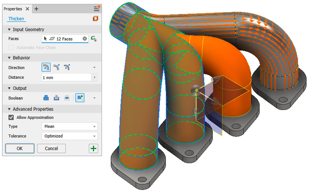
Figure 4.59: Second Thicken operation to complete and faces to select
- Create a new Thicken operation with the same values as step 51 on the remaining faces as per Figure 4.60:
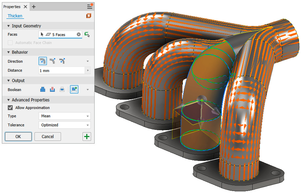
Figure 4.60: The last Thicken operation to complete and faces to select
- The preview of the model will display the material and the surface at the same time. This can be confusing, so now that the Thicken operation is complete, we can hide the visibility of the underlying surface. In the Model Browser, right-click on Stitch Surface1 and select Visibility.
- To make modifications to the model easier, we will now combine the several solid bodies of the model into one. Navigate to the Model Browser and note the Solid Bodies folder. It is populated with seven separate solid bodies.
- With the 3D Model tab active, navigate to the Modify panel and select Combine.
- Select Basebody and then select all the solid bodies in the graphics window, as shown in Figure 4.61:
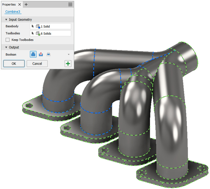
Figure 4.61: The Combine operation and settings to apply
- Select Join and then OK. The solids have now been combined into a single solid. The Solid Bodies folder in the Model Browser should now say (1).
- Select Fillet and then select the edges shown in Figure 4.62. Add a Fillet value of 15 mm and select OK. If the Combine operation had not been carried out, the fillet would not have been computed this way, as Inventor would have still recognized this model as separate solid bodies:
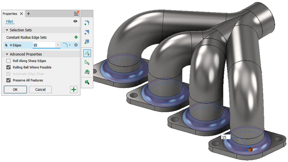
Figure 4.62: 15 mm fillet to apply to the model
- We now need to design the next plate on the outlet of the exhaust manifold. To do this, we will use the Ruled Surface command.
The Ruled Surface feature creates surfaces that extend a specified distance and direction from a selected edge. They are effective to use in casting or molding designs, as a draft can easily be added or to create smooth extensions to complex surfaces.
As we will be working with overlapping surfaces, it is easier to change the background from white to something else temporarily to make seeing the surfaces much easier.
Go to File | Options | Colors Tab. Change In-canvas Color Scheme from Presentation to Forest (this can be changed back later). Then, select Apply.
- From the Surface Modelling tools, select Ruled Surface.
- There are several types of ruled surfaces that can be created – for this, we will select the Normal option. This will create a surface normal for the selected edge.
Select the outer edge of the exhaust manifold, as shown in Figure 4.63.
- Set Distance to 40 mm (you may need to flip the direction if the preview does not display). Then, select Apply to create:
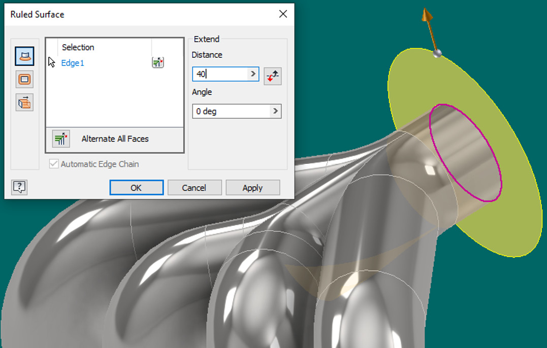
Figure 4.63: Ruled surface applied to the opening of the exhaust manifold
- With the Ruled Surface command still active, select the edge of the ruled surface created in step 62. This is shown in Figure 4.64.
- Change Angle to -20 degrees and Distance to 30 mm:

Figure 4.64: Second ruled surface added with a -20-degree draft
- Select Apply to complete.
- Then, select the Stitch command.
- Select the two RULED SURFACES created as the surfaces and select Apply, followed by Done to complete the stitch.
- Select the Thicken/Offset command.
- Select the stitched ruled surface as the surface to thicken.
- Set Distance to 3 mm and Direction to Outside.
- Select Join as the Boolean operation; this will join these solids to the existing solid.
- Select OK and hide the internal surface once complete. The Thicken operation should result in Figure 4.65. You can also add a 10 mm fillet to the outer edge and two 20 mm holes to complete it:

Figure 4.65: The Thicken operation complete on ruled surfaces with an optional fillet and holes added
Using 3D sketches, you have created centerlines for several complex surface sweep operations. You have also successfully trimmed, stitched, thickened, and combined the surfaces to create the exhaust manifold and transform this into a single solid body. Finally, you have applied ruled surfaces to create the end plate for the outlet.
Learning how to trim, patch, and convert surfaces to solids with Sculpt
In this recipe, you will learn how to apply the Trim and Patch Surface commands and how to use the Sculpt command to convert surfaces into solids.
Getting ready
Open Surface_Part.ipt from the Chapter 4 folder.
How to do it…
With Surface_Part.ipt open, we will start to trim the existing surfaces to the desired profiles, followed by extending a profile and patching the gaps in the surface. We will then convert this to a solid model. To get started, see the following:
- Select the Trim command from the Surface tools. We will use this to trim one surface from another to create the desired profile.
- Select ExtrusionSrf2 as the cutting tool and Extrusion Srf1 as the section to remove, as shown in Figure 4.66:
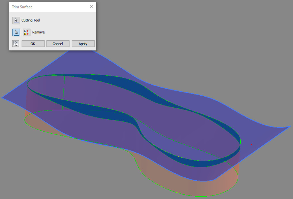
Figure 4.66: Trim Surface options to select on Surface_Part.ipt
- Select Apply to complete.
- With the command still active, select the following surfaces shown in Figure 4.67 to trim them from the model:

Figure 4.67: Second Trim operation to apply
- Extend can be used to extend surfaces the desired amount. Select Extend from the Surface commands.
- Select the flat edge as shown in Figure 4.68, change the extension to 4 mm, and select OK:
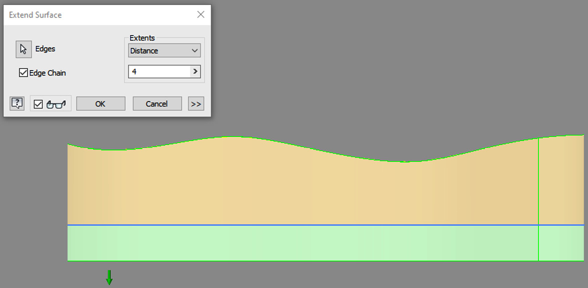
Figure 4.68: The edge to apply an extended surface
- One end of the surface is open-ended. In this example, we need to close this boundary. One of the most important and useful surface commands that we can use to accomplish this is the Patch command. Patch allows you to close a gap between surfaces and tangency and G2 curvature can also be applied if required. The addition of guide rails can be used further to control the surface’s continuity. So, select the Patch command from the Surface tools.
G2 curvature
If the radius of curvature is the same value at the common endpoint, the curvature is classed as continuous (G2).
- Select the edge shown in Figure 4.69, and in the edge selection area, activate the drop-down menu and select Tangent Condition. This applies a tangency to the boundary patch.
- Modify the Weight setting of the tangency from .5 to .2 and then select OK:

Figure 4.69: Edge to select for the patch
- Select Stitch and combine the surfaces together to create a composite surface.
- Now, we need to convert the surfaces into a more usable 3D solid or solid body. To do this, we can use the Sculpt command. Select Sculpt from the Surface commands.
- Select the surfaces to sculpt. Ensure New Solid is active in the window and select OK. This will convert your stitched surface into a solid body:
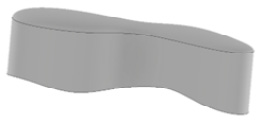
Figure 4.70: The surface converted to a solid body model using Sculpt
You have successfully applied Surface Trim, Extend, and Patch to create the desired outcome of this surface and converted the surface into a solid body.
Replacing a solid face with a surface
In this recipe, you will take an existing model and replace the face with that of an intersecting surface.
Getting ready
Open Replace Face.ipt from the Chapter 4 folder.
How to do it…
To begin, we will use the Replace Face command to select the solid face we wish to replace with the chosen surface:
- A swept surface profile has been swept along a 3D block. The surface intersects with and passes through the block. Using Replace Face, we can transform the flat surface of the block to reflect the surface sweep that intersects it. Select Replace Face from the Surface Modeling tools.
- Select the existing face as the flat top of the block.
- Select the swept surface as the new face, as per Figure 4.71:

Figure 4.71: Existing and new faces to select with the Replace Face tool
- Select OK. The flat face has been replaced with the complex swept surface, as shown in Figure 4.72.
- Right-click on SweptSrf2 in the Model Browser and select Visibility to hide the surface:
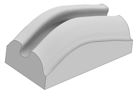
Figure 4.72: The completed surface of Replace Face.ipt
- The original sketch that was used to create the swept surface adapts to the changes we have made in the Replace Face command. We will now observe this, expand SweepSrf2 in the Model Browser, right-click on Sketch 3, and then Edit Sketch.
- With the mouse, pull one of the spline points so that the sketch resembles Figure 4.73. Select Finish Sketch. The 3D model updates as per your changes to the spline:
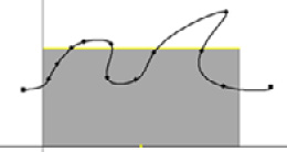
Figure 4.73: The change to make to one of the spline control points in Sketch 3
You have used Replace Face to replace an existing solid body face with that of a complex surface.
Using the Copy Object command to create a matching contoured part to another part
In this recipe, you will use Copy Object to copy the existing faces on a part file as a surface and then use Thicken/Offset to create a contoured part. We will then make changes to the original part using Direct Edit and the changes will be reflected in the overall assembly automatically
Getting ready
Open Copy_Object.iam from the Chapter 4 folder.
How to do it…
We will begin looking at the existing model and then creating an in-place component within the assembly. So:
- With Copy_Object.iam open, select the Assemble tab and then click Create from the ribbon. Here, we will start the creation of an in-place component within the context of the assembly.
- Rename the new component Casing.
- Browse the Template drop-down list and select MetricStandard (mm).ipt.
- Leave the file location and BOM structure as their defaults. Then, select OK:
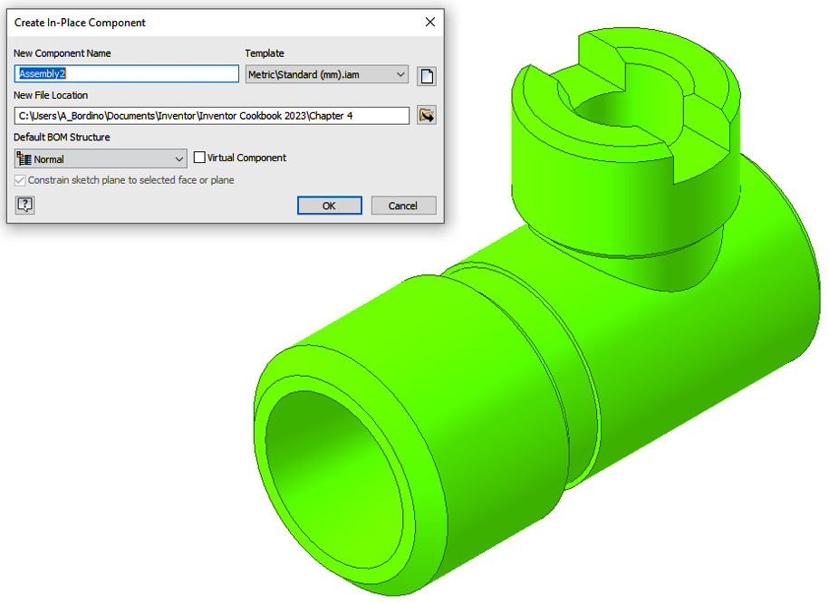
Figure 4.74: Creating an in-place component within the context of the assembly
- You are now prompted to select a plane to start the creation of the part. Select the YZ plane from the Model Browser.
- The Edit Part environment is now open for the new Casing.ipt part we are creating. Open the Modify drop-down menu and select Copy Object.
- Then, click Bodies and select the Copy Object part from the graphics window, as shown in Figure 4.75:
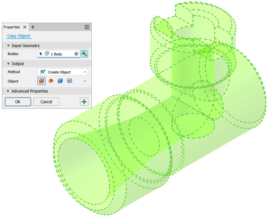
Figure 4.75: The Copy Object window and options to select
- Ensure that the Method option is Create Object and the Object type is defined as Surface.
- Select OK. The Copy Object command has now created a surface skin of the model.
We can now adapt this and use a Surface Delete tool to remove unwanted surfaces.
- Right-click on Surface 1 in the Model Browser and disable Translucency.
- In the Modify tab, select Delete Face. This is used to delete unwanted surfaces and faces.
- To delete a face, with the command active, select a face or surface on the model in the graphics window and select OK. Note more than one face can be removed in one operation.
- Delete all faces until the surface resembles Figure 4.76:

Figure 4.76: Deleting all surfaces until your model resembles this
We now have defined the extent of the contoured casing with surfaces.
- Now, we will add solid geometry to this. Select Thicken/Offset from the Modify tab to add solid geometry to the surfaces.
- Select the eight faces shown in Figure 4.77 to apply Thicken. Set Direction to Outside and Distance to .5mm:

Figure 4.77: Surface faces to apply the Thicken/Offset command to and the values to apply
- Select OK to complete.
- Right-click on Casing:1 from the Model Browser. Select iProperties and then open the Physical tab. Change the Material option to Rubber and select Apply.
- Close the iProperties menu and select Return in the ribbon to return to the assembly.
- We have now created a contoured part from the original using surfaces. As the new part is adaptive, if changes are made to the original, they will automatically translate to the casing created. Right-click on Copy_Object.ipt from the Model Browser and select Edit.
- Select Direct Edit from the Modify tab.
- Select Scale as the operation and then select the solid of Copy_Object.ipt, shown in Figure 4.78:
- For the scale value, change this from 1.0 to 1.5 and ensure Uniform is selected. As the new scale value is entered, it will be reflected in the graphics window in real time:
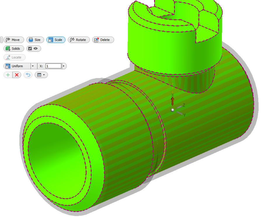
Figure 4.78: Direct Edit in progress on Copy_Object.ipt
- Select the green + icon to complete the scale.
- Select Return from the ribbon to return to the assembly file.
- The contoured Casing.ipt we created previously has automatically updated in scale to suit Copy_Object.ipt, shown in Figure 4.79:
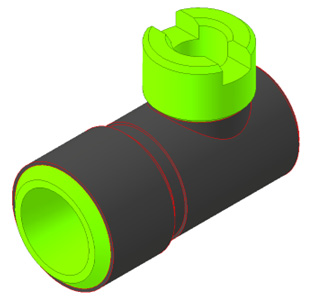
Figure 4.79: Returning to the assembly activates the adaptive casing we created to update in scale to suit the original pars
In this recipe you have used Copy Object to select the desired faces on an existing model, convert to surfaces, edit, and delete unwanted surfaces with Delete Face, apply solid material to the surfaces, and create an adaptive contoured casing, that has updated from the result of a scale operation using Direct Edit.
Importing surfaces into Inventor
It is sometimes necessary to import surfaces or CAD files from non-native CAD formats into Inventor. Inventor is very capable of importing and using non-native CAD data and in this section, we will examine how Inventor can import surfaces from non-native CAD files and what modifications are possible.
It is not uncommon for imported surfaces to translate with some errors. Fortunately, Inventor has an array of Surface Repair tools that can be used to identify, locate, and correct surface bodies.
In this recipe, you will import a .iges file as a surface. The same process is used to import any non-native CAD data into Inventor.
Getting ready
For this recipe, you will need a new Inventor part file open.
How to do it…
To begin, we will need the new Inventor part file open; we will then start the process of importing in the .iges file. To do this, see the following:
- Select File | Open | Import CAD Files.
- In the dropdown for File Type, select All Files.
- Find and select the Import.igs file. Then, click Open.
- The import options are now open (Figure 4.80) and you can choose how you would like to import the file:
- Deselect Solid and select Surface.
- You can also define the units at this point – however, we will leave this as the default.
- Under Surfaces, the dropdown allows you to select from Individual, Composite, or Stitch. In this example, we want to import the entire model as a surface, so Composite will work best:
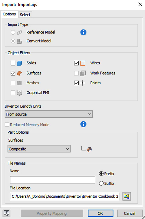
Figure 4.80: Import options available on the IGES file to be imported into Inventor
- Then, select OK to complete the import. The .iges file has now successfully been imported into Inventor as a composite surface.
- Inventor will notify you as the user if errors are present in the model. To fix these, you must navigate to the Repair Bodies command in the surface commands area of the ribbon. This opens a new environment for the Surface Repair tools. In this case, the surface has been imported without issue, as a green tick is visible next to the composite name in the Model Browser.
As this is an error-free surface with healthy geometry, we can work on the model without issue.
- Now, close the model.
You have now imported a non-native .iges file into Inventor as a composite surface.
There’s more
In some cases, it may be necessary to perform repairs on an imported surface model. Issues that may arise could be missing faces, intersecting geometry, or missing aspects of the model that were not translated across in the model.
For the full list of compatible files that Inventor 2023 can import, please see https://help.autodesk.com/view/INVNTOR/2022/ENU/?guid=GUID-AF41FA87-7588-4698-9C41-756A01EBE7F4.
The main objective when repairing an imported surface with errors is to create a watertight surface, with closed boundaries, so that a solid geometry can be generated from it.
To repair an imported surface, the typical workflow is as follows:
- Select Repair Bodies to open the Repair environment
- Select Find Errors to identify where the errors are
- Use Stitch and close the surfaces together
- Conduct an error check
- Use Stitch and close further if necessary
The Repair environment can be accessed by selecting Repair Bodies in the Surface Modeling area of the ribbon. The ribbon will then transform as Figure 4.81 shows. The Repair functions are designed to be used left to right and you can find the Find Errors command on the far left:
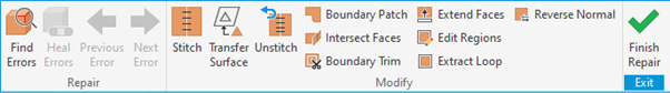
Figure 4.81: The Inventor Surface Repair ribbon
Upon activating Find Errors, you can then choose Select All Surfaces to select all the surfaces in the model. It is advised that in most cases, this is what should be done to ensure all the imported surfaces are analyzed.
The error check performed will then analyze all the imported surfaces and report back any errors to you via the Model Browser. Surfaces with errors will show with either an exclamation mark in a circle or a warning triangle. Geometry that has passed the check will show with a green tick. Figure 4.82 shows the errors visible in the Model Browser and graphics window:
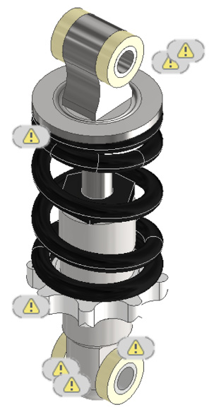
Figure 4.82: Warning symbols on a model
Inventor will group similar errors into folders within the Model Browser. You can also use the Next and Previous commands in the ribbon to cycle through the errors identified.
Once an error has been identified, it can be manually fixed through stitching and other functions or the Heal Errors command can be used. This tool only becomes visible once an error has been identified.
When the relevant bodies have been selected, the Analyze Selected Bodies function within Heal Errors can be used to resolve issues within the specified tolerance range. If the error cannot be healed automatically, the tools in the Modify panel must be used to manually correct the geometry.
Once the errors have been identified, use the Stitch command to close the gaps and ensure you are left with a complete surface. The Patch and Extend tools can also be used to achieve this.
Validating surface designs with Zebra Analysis, Surface Analysis, and Curvature Analysis
Inventor has a range of analysis tools that focus on surfaces and surface quality. This is important, as often as a designer, you need to ensure and validate the surface design before manufacture and ensure that the surfaces blend or transition appropriately without any sharp changes in curvature or smoothness. This can be particularly important for molded components and products.
In this recipe, you will make use of three of the common surface analysis tools: Zebra Analysis, Surface Analysis, and Curvature Analysis.
Getting ready
For this recipe, open Bike_Saddle.ipt in the Chapter 4 folder.
How to do it…
First, we will examine the part, then apply the relevant surface analysis tool and examine the results. To do this, see the following:
- To begin, we will examine the Surface Inspection tools. Select the Inspect tab, go to the Analysis panel, and then select Surface.
- From the Surface Analysis drop-down menu, select the type of curvature calculation you want to perform. There is a range of options that you can choose from and each represents different aspects of curvature. They are as follows:
- Gaussian: Displays a gradient representing the product of the curvature – the curvature in the U direction of the surface multiplied by the curvature in the V direction of the surface. Use this for looking at shapes such as coils or sweeps.
- Mean Curvature: Displays a gradient representing the mean curvature of the U and V surface curvature values. Used for cylindrical or cone features, typically suited to lofted profiles.
- Max Curvature: Displays a gradient representing the greater of U or V surface curvature values. Ideal for analyzing areas of low and high curvature.
For this example, select Max Curvature.
- We can now specify the ratio gradient range that we want to look at in the model.
The options to pick from are as follows:
- Minimum Curvature Ratio: Sets the value that maps the start (blue end) of the color gradient
- Maximum Curvature Ratio: Sets the value that maps the end (green end) of the color gradient
- Auto Range: Sets the minimum and maximum curvature ratio that the analysis display uses
For our analysis, select Maximum Curvature Ratio.
- You can also specify the gradient values and set these. In this recipe, we need to select Auto Range.
- There is a slide in which you can alter the display quality, which determines the resolution or quality of the gradient or color bands. As we are not using the gradient setting, leave this as the default.
- We now need to select the faces or surfaces that we want to analyze. By default, under Selection, this checkbox is checked, meaning the whole model will be analyzed. Select the check box to deselect All.
- Select the two faces shown in Figure 4.83. Ensure that your curvature settings also match those shown in the screenshot:

Figure 4.83: Curvature surface analysis settings and faces to apply to Bike_Saddle.ipt
- Select OK. The curvature surface is displayed on the faces as per Figure 4.84:
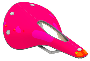
Figure 4.84: The Maximum Curvature gradient displayed on the model
Now that this has been applied, you will notice in the Model Browser that an additional folder called Analysis Surface has been created automatically. This stores all the surface analysis studies so they can be turned on or off and edited within the model.
- Next, we will look at the Zebra Analysis tool. This can also be used to validate the surface continuity smoothness and gradient. From the Inspect tab, select Zebra.
Note
To understand and interpret Zebra Analysis surface continuity, see https://knowledge.autodesk.com/support/autocad/learn-explore/caas/CloudHelp/cloudhelp/2016/ENU/AutoCAD-Core/files/GUID-82E5989F-C943-49A6-A6C6-834B81CC203B-htm.html.
- We can now define the thickness and orientation of the analysis. Leave all settings as default in this case, except for Thickness, which you should reduce slightly as per Figure 4.85.
- Deselect All in Selection. Select the two faces you previously analyzed for curvature and then select Apply:
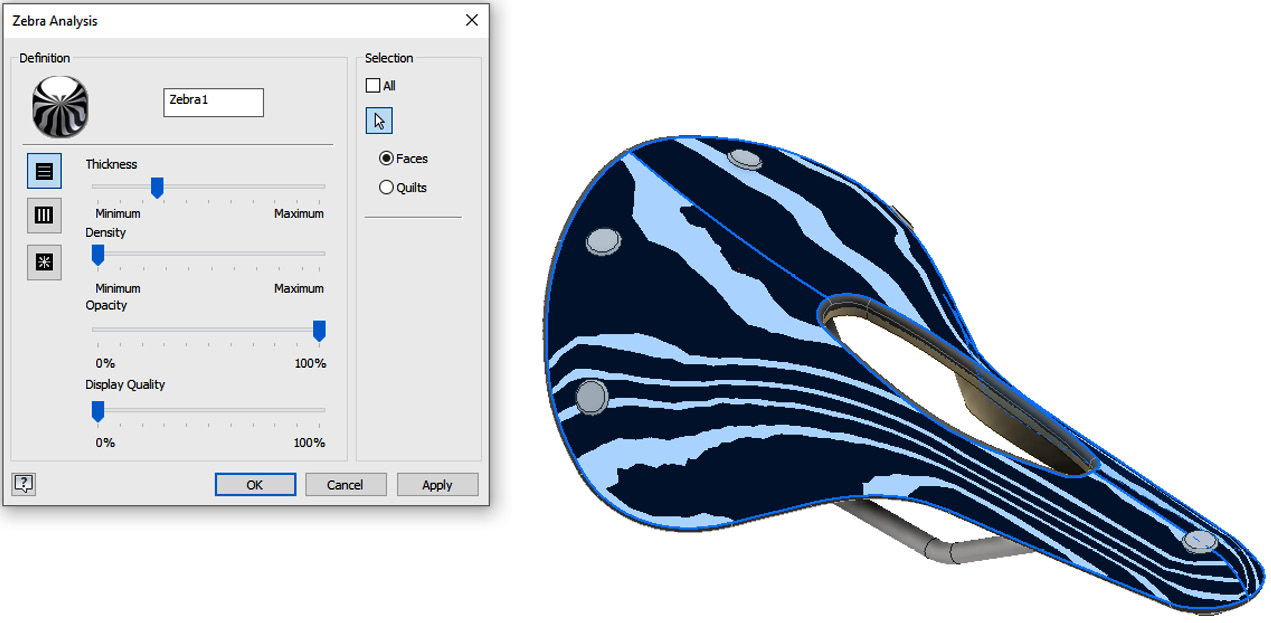
Figure 4.85: Zebra Analysis applied to Bike_Saddle
Note that the Analysis folder now has both the surface and zebra studies within it. You can double-click each instance in the Model Browser to flip between Zebra and Curvature. Edits can also be made by right-clicking on the study in the Model Browser.
- Now, we will look at and examine Curvature. The Curvature tool provides a visual analysis of the curvature and overall smoothness of model faces, surfaces, sketch curves, and edges. Select Curvature from the Inspect tab.
- With Curvature Analysis, you can select and alter the height and density of the combs that will be placed on the chosen surfaces. Change these so they reflect the settings in Figure 4.86:

Figure 4.86: Curvature Analysis settings to apply on the surfaces
- Select the two faces of Bike_Saddle.ipt previously selected for the other two Surface Analysis studies. Select OK to complete.
You can now apply several Surface Analysis tools to examine, validate, and check designs.
Understanding the basic features and techniques of freeform modeling
The Freeform modeling workflow and tools within Autodesk Inventor allow you to easily create complex visual forms and models without the constraints and precision required in solid modeling workflows. The Freeform tools enable you to push and pull material in an organic way to create true curves and specialized organic forms. Freeform modeling poses G2 continuity across all created surfaces.
The freeform workflow can also be combined with the uses of surface modeling and solid body modeling. Learning all the freeform modeling techniques takes time, persistence, and dedication. In this section of the chapter, we will focus on the basics to get you started with freeform modeling in Inventor.
In this first Freeform recipe, you will be introduced to the Freeform environment and create a basic Freeform box shape – you will then manipulate this to learn how some of the basic tools and commands work in this environment.
Getting ready
For this recipe, you will need to open a New Standard (mm.ipt part file.
How to do it…
To get started with the Freeform environment, see the following:
- Firstly, we need to define how we want to work in the Freeform environment. In this instance, we will start with one of the preset freeform shapes and edit it to suit.
Within the 3D Model tab, under Create Freeform, select Box (note that in the dropdown, there are other options we can choose from, but this is what we are choosing for now).
- You will then be prompted to further define the box shape. We can specify the length, width, height, and number of faces. The more faces that you apply, the denser the freeform mesh will appear on the part, and the more control you can apply to the form. With freeform modeling, it is often the case that you will also want to apply a degree of symmetry to the model and this can also be achieved in this window.
For our example, apply the values shown in Figure 4.87 for Length, Height, and Width. Then, select Width Symmetry.
- Select the XY plane to generate the base form of the box as defined, also shown in Figure 4.87. When the origin is selected, the freeform box is created:

Figure 4.87: Freeform box options to select
- Select OK. The freeform box as we previously defined in the freeform box creation window is now in the graphics window and we can begin to edit it. Note that the Width Symmetry rule we applied will remain throughout. Your graphics window should now display the following shown in Figure 4.88. Note also that the ribbon has now transformed to reveal the Freeform Modeling tools:

Figure 4.88: Freeform modeling environment active
- Navigate to the ribbon, then click Toggle Smooth from the Tools panel. This enables you to switch the model from a smooth freeform display to a block display style. This is a visual tool that is used to improve performance. In this instance, we will keep the display Smooth.
- There are several freeform model tools, and at any time, you can exit Freeform Modeling and resume surface or solid modeling workflows. The main command used in manipulating freeform shapes is the Edit Form command. In the ribbon, select Edit Form.
- We are now able to specify entities to pick. On the Filter options, All is selected, which means we can select any face, edge, or point on the form; this offers the most flexibility, so leave this as default.
In the Transform section, we can define whether we want to move the existing faces or scale them. You can also define how the faces are selected with Selection Options, based on individual items.
Apply the settings shown in the window in Figure 4.89:

Figure 4.89: Vertexes to select and pull downward to manipulate forms
- Then, hold Shift and select the three vertex sections along the symmetry line on the form.
- With the graphical arrows displayed, select the up arrow and pull this down around -10.25 mm. The result is also shown in Figure 4.89.
Tip
As well as manually dragging the arrows in Edit Form, you can also type specific values if required.
- With the Edit Form command still active, select the face shown in Figure 4.90. Note how the opposing identical face on the other side of the model is also selected:
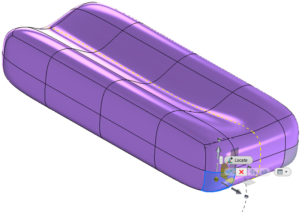
Figure 4.90: Face to select on the form
Pull the face by 30 mm in the direction shown in Figure 4.91. The same is applied on the opposite side of the mode. This is because Width Symmetry was defined in the Form Creation stage:
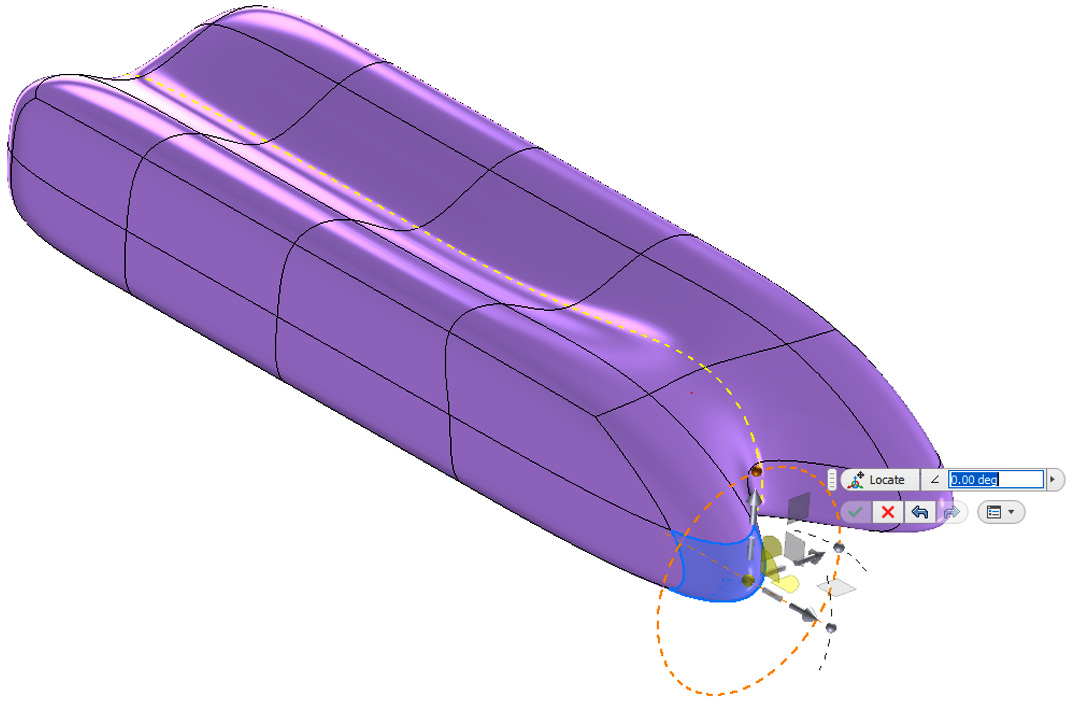
Figure 4.91: Face pulled out 30 mm and replicated through the line of symmetry
- Select the rotation node and twist it 90 degrees in the direction shown in Figure 4.92:
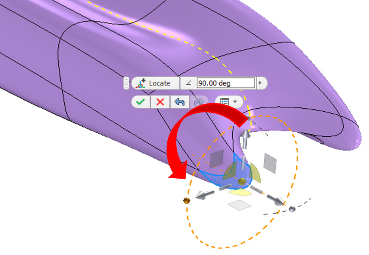
Figure 4.92: Rotation node selected and moved 90 degrees, twisting the previous extension from the form
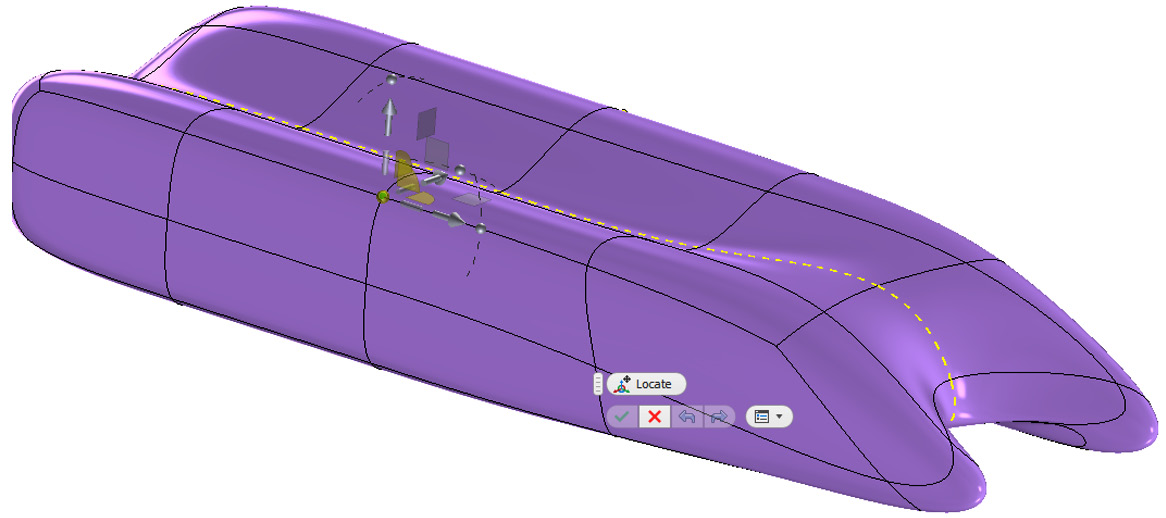
Figure 4.93: Point on the form to be selected
Pull the point inward towards the center of the model by 13 mm as shown in Figure 4.94:

Figure 4.94: Point on the form selected and pulled inward 13 mm
- Faces in the form can also be further subdivided. This is ideal if there is refined detail that needs to be added or if you require greater control of a face to create the desired geometry.
Select Subdivide from the Modify panel.
- Increase Faces, Width, and Length from 2 to 3.
- Select the face shown in Figure 4.95; the face will then subdivide as specified:
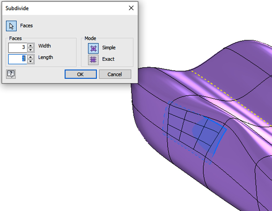
Figure 4.95: Subdivide settings and face to apply
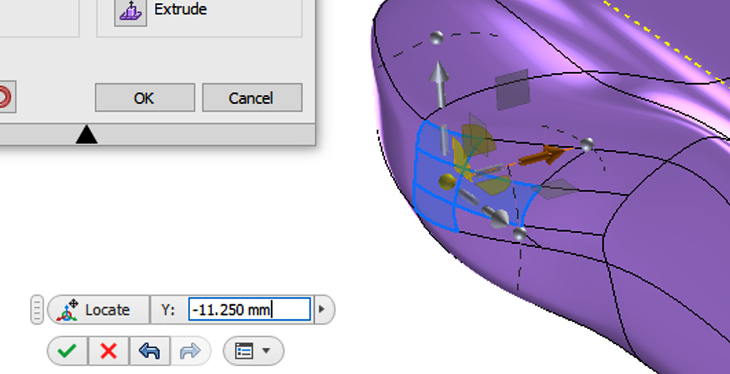
Figure 4.96: Three subdivided faces on the form selected and pulled outward
- Once an edit has been made to a subdivided face, the edge can be deleted if required. Select Delete from the Edit panel, select an edge, and then click OK. The result is shown in Figure 4.97:
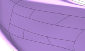
Figure 4.97: Edges deleted from a subdivided face using Delete
- Select Finish Freeform. The model reverts from the freeform environment to the modeling environment (Figure 4.98) and the form is transformed into a solid geometry. Standard solid modeling workflows can now be used:
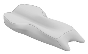
Figure 4.98: Completed form transformed into a solid body model
At any point, you can return to the freeform tools by right-clicking on Form 1 in the Model Browser and selecting Edit Form. You have now used the basic Freeform tools to define a shape and convert it into a solid.
Freeform modeling within the context of existing geometry
Freeform modeling is mostly conducted in the context of an assembly or with existing components. In this recipe, you will perform a freeform modeling exercise to create an ergonomic handle for a hand grinder in the context of an assembly. You will then convert the freeform into a surface, make further edits, and then sculpt it into a solid geometry.
The completed model you will create is shown in Figure 4.99:
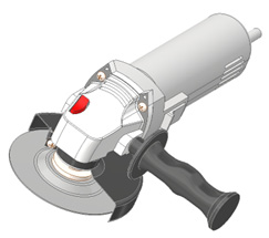
Figure 4.99: Completed angle grinder model
Getting ready
In the Chapter 4 folder, open the Hand Grinder folder, and then open 4.5 in Grinder Assembly.iam.
How to do it…
Once 4.5 in Grinder Assembly.iam is open, you will see that the hand grinder is complete except for the handle. This is the segment of the design you will complete using the Freeform Modeling tools. Figure 4.100 shows the model open:

Figure 4.100: 4.5 in Grinder Assembly.iam
To begin with, we will have to find the component we want to edit within the context of the assembly.
- In the Model Browser, right-click on Grinder Handle and select Edit. You are now editing the handle in the context of the assembly.
- Select Create Freeform and select Cylinder.
- Select the face of the Grinder Handle part, and then select the midpoint to place the Cylinder freeform, shown in Figure 4.101:
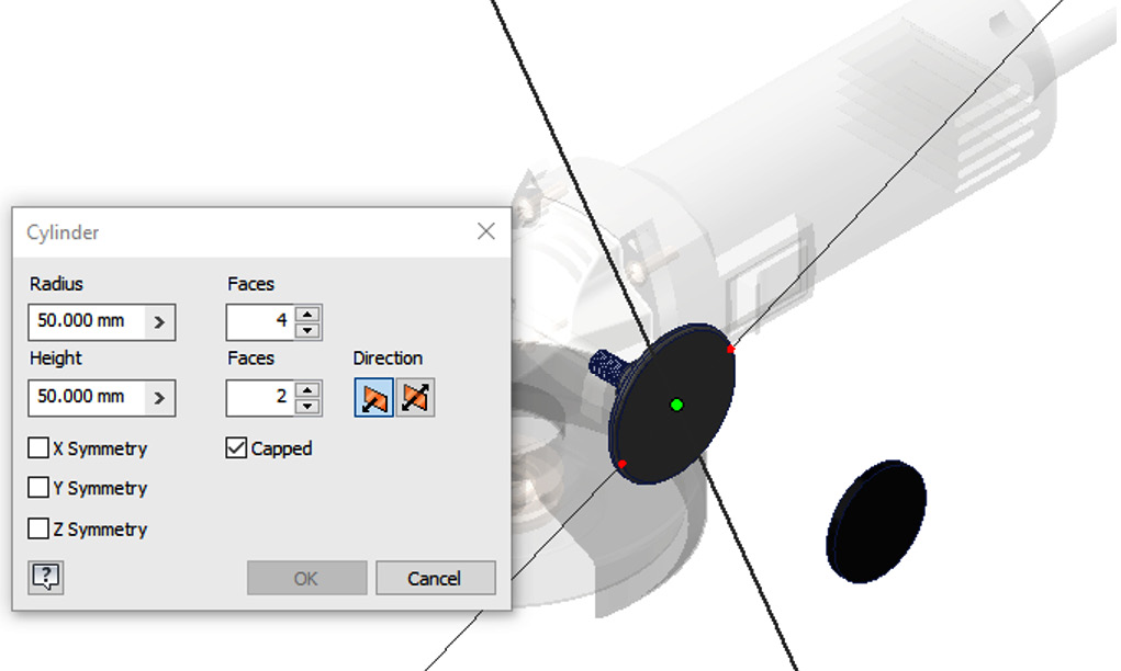
Figure 4.101: Placement of the Cylinder freeform
- Left-click to place the freeform cylinder. You can see the default cylinder in Figure 4.102:

Figure 4.102: Default freeform cylinder placed
- We will now refine the cylinder so that it is closer to our desired shape. Define the cylinder properties as per Figure 4.103 and then click OK to complete the cylinder:
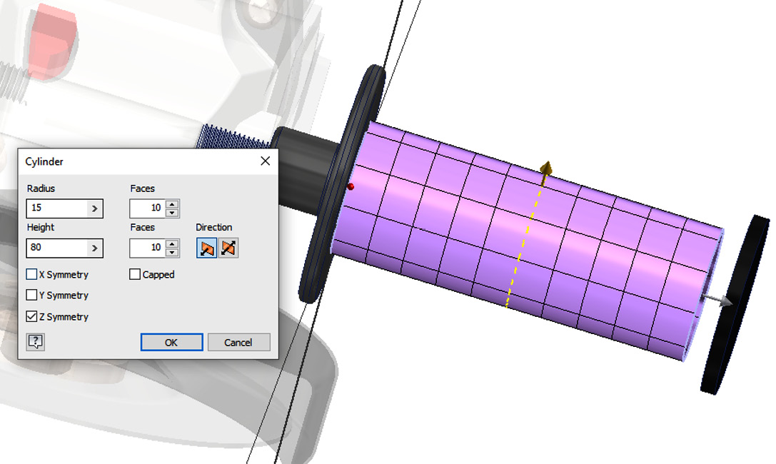
Figure 4.103: Cylinder properties to define
- Select Edit Form. Select the Freeform faces as shown in Figure 4.104. The Z symmetry will apply symmetry and any changes to the other side of the model:
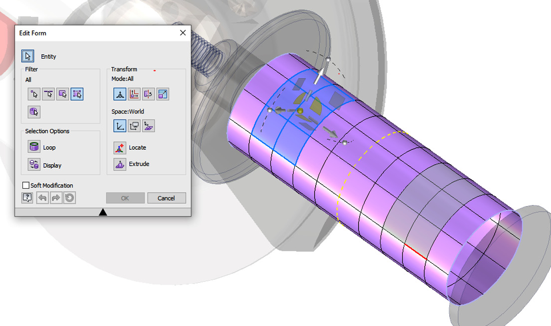
Figure 4.104: Freeform faces to select
- Pull these faces downward by -4.24 mm as shown in Figure 4.105. It is best to navigate to the left view in View Cube to do this:

Figure 4.105: Faces pulled downward -4.24 mm
- Select the green tick to complete the edit form operation.
- Select Edit Form and navigate to the bottom view on the View Cube.
- Then, select the faces shown in Figure 4.106:
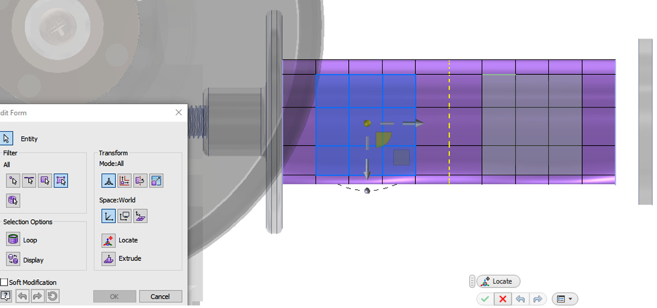
Figure 4.106: Faces selected to perform the next edit
- Navigate to the left view on View Cube.
- Select the sphere node and pull upward; this will flip the orientation of the arrows so we can pull the feature in the correct direction, as shown in Figure 4.107:
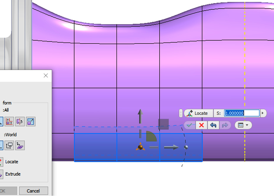
Figure 4.107: Sphere to select to re-orientate the Freeform control arrows
- Pull the arrow pointing upward up so that the model resembles Figure 4.108:

Figure 4.108: Pull the freeform arrow shown to create the shape shown
- Select OK and then select Finish Freeform in the ribbon.
Because we uncapped the ends of the original freeform cylinder, the freeform model has transformed into a surface model.
- We now need to create a joining surface where there is currently a gap. In the Surface Tools panel, select Patch.
- Select the two boundaries shown in Figure 4.109 and select OK:

Figure 4.109: Boundaries to select shown and the Patch operation performed
- Select OK. From the Surface panel, select Sculpt.
- Select the two surfaces that make up the handle, as shown in Figure 4.110:
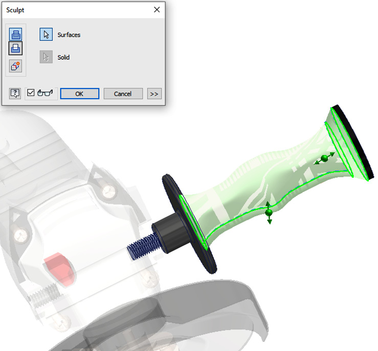
Figure 4.110. Surfaces to modify
- Select Add as the option, followed by OK. This transforms the surfaces into a solid geometry.
- Select Return to return the assembly.
You have successfully used the Freeform tools to design and create an ergonomic handle for the hand grinder within the context of an assembly.
Model credits
The model credits for this chapter are as follows:
- EV charger type 2 plug(female) (by Brandon) https://grabcad.com/library/ev-charger-type-2-plug-female-1
- 4.5 Inch Grinder (by David Guza) https://grabcad.com/library/4-5-inch-grinder-1
- Brooks C17 (by max morozov) https://grabcad.com/library/brooks-c17-1