
5
Advanced CAD Management and Collaboration – Project Files, Templates, and Custom Properties
Setting Inventor up correctly for your organization is important to ensure that all users are using the right files, content, and template files. This enforces and encourages standardization and a code of best practice within the design department. The correct setup and project management save time and improve the efficiency and flow of work. Most designers and engineers spend far too much time trying to locate the correct files for a job. Ensuring that the right templates are active and that Inventor is set up for your organization’s workflows is crucial. In this chapter, we will learn about the CAD management aspects of Inventor, how you can set up templates, and the collaboration tools at your disposal.
Inventor can work with a dedicated Product Data Management (PDM) solution – Autodesk Vault. This chapter will not cover workflows, setup, or project management involving Autodesk Vault, as this is a separate product. If you wish to learn more about Vault, contact your local authorized Autodesk partner, who will be able to best advise on this.
In this chapter, we will learn the following:
- Creating and managing an Inventor .ipj project file
- Managing the Content Center
- Style and Standard Editor – creating and editing templates
- Collaborating with shared views
- Collaborating and sharing designs with Pack and Go
Technical requirements
To complete this chapter, you will need access to the practice files in the Chapter 5 folder within the Inventor Cookbook 2023 folder.
Creating and managing an Inventor .ipj project file
Before embarking on a practical recipe for creating and managing an Inventor project file, it is important to understand the terminology and nomenclature and how the project file system works within Inventor.
Inventor uses project files to organize and collate all the design data associated with a job or project that you are working on. Projects can consist of parts and assemblies but also standard components, and libraries of the standard components used, such as fasteners.
Inventor projects act as a central repository and location for your design files, so Inventor knows the location of all parts and assemblies that are associated with a particular design job.
There is no limit to the amount of project files that you can have to manage your work within Inventor. There are normally two schools of thought about managing projects in an organization:
- A single project with an internal folder structure within it for each job/project (which is also arguably the best setup for projects if you use Autodesk Vault)
- Multiple individual project files for separate jobs
There is no right or wrong setup, and this is entirely dependent on how your organization wants to work, and your design process. The Inventor 2023 Cookbook project is a single project, with all design files stored within a folder structure.
An advantage of using a single project is that you can open multiple design files from multiple jobs and projects at once. If you had parts or assemblies stored in different projects that were required for a job, you would not be able to open them at the same time, as Inventor only allows the user to have one project active at any given time. If the files are stored in another project, then you must close all current data for the current project and then activate the required project to access the files.
By default, in Inventor 2023, three projects are installed with the Inventor software: default, sample and tutorial files. Migrating the files to another project once a design is completed is difficult and complex. It pays dividends to spend time ensuring your setup is right the first time!
Inventor projects are stored as project files (.ipj files) to store the paths to folders where your design data is located.
A Project.ipj file is a text file in .xml format. The project wizard creates this automatically when a project is created. The file specifies the paths to folders that contain the files in the project. These stored paths assure that links between files work properly. When you open a file in a project, Inventor uses the search paths in the order they appear so that it can find the file and any referenced files. For example, if an assembly is opened, Inventor can find all the related parts and assemblies within the project that relate to this. If parts are stored in a different project or separate .ipj file, Inventor will flag errors, stating that it cannot find the path. You will then have to manually find the specific file.
In this recipe, you will create a new Inventor project file, complete the setup and configuration of this, and then test your project file by adding some parts to it.
Getting ready
You will not need any practice files for this recipe. Just navigate to the Inventor Home screen to begin.
How to do it…
We will first begin on the Inventor Home screen:
- Select the vertical ellipses button next to the active project, and select Settings, as shown in Figure 5.1:
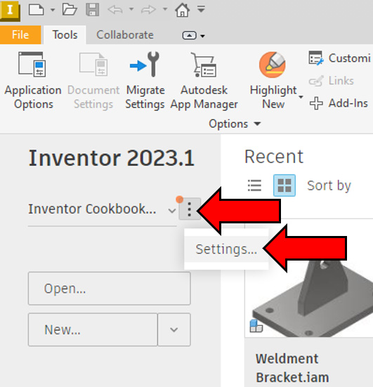
Figure 5.1: The location of the projects area of Inventor
The project wizard will now open, which displays your current active project and a list of other available projects. Note that the list of projects shown in Figure 5.2 may be different on your machine.

Figure 5.2: The Projects window active
- Select New in the Projects window.
- Ensure that New Single User Project is selected, and then select Next. New Single User Project does not mean that the project is limited to its use by one individual user; it just means that this is an Inventor project that is not using Autodesk Vault.
The New Vault Project would be selected if we were using the dedicated PDM product, Autodesk Vault, to manage our CAD data, which includes extra setup, settings, and options that must be defined to ensure we link a project to a Vault. In this case, we are not using Autodesk Vault, so New Single User Project will be fine:

Figure 5.3: The project wizard window
- The next step is to name our project. Projects typically are named after the organization or the client the project is for, although you are free to name your projects whatever you want. In this example, type the name of the project as Test Project.
- The next important aspect to define is the project location or workspace. This is the top level of the project that will contain all other subfolders and files associated with the project. All files created will be saved underneath this folder. You can browse a location on a drive to find a place to store this. In this example, leave it as default.
Select the three dots next to the Project (Workspace) Folder option and browse the new location of your project file. Select the C: drive and create a new folder called Test Project. Figure 5.4 shows the result of completing this. Your project location should now be C:Test Project:
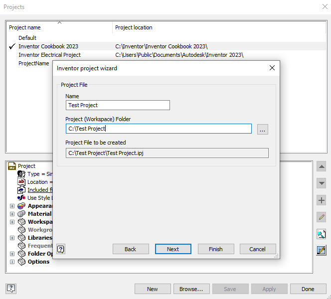
Figure 5.4: Creation of the new project workspace on the C: drive
Collaborative project files
If working in a collaborative environment, the project file should be stored on a network drive so that all other users can collaborate and access project data. With Autodesk Vault, you have much more control in terms of user permissions and who can access what files and at what revision or life cycle state. Out-of-the-box Inventor Professional does not contain these features.
- Select Next. The following window allows you to set up and share standard library parts across projects. For example, you may have another folder location on a network drive that contains several standard parts required in your projects. In this case, it is not necessary.
To proceed, hit Finish to complete the creation of the new project, Test Project, which will now become the active project in Inventor. This is shown by the check mark that is displayed next to the project name. Remember that only one project can be active at any one time in Inventor.
- Navigate to the C: drive and open the Test project folder. Note that a Test Project.ipj file has now been created:

Figure 5.5: Test Project.ipj created in the Test Project folder or workspace
- Navigate back to the Inventor Home screen.
- Ensure that Test Project is still the active project in Inventor, and the check mark should be displayed next to the name in the Projects area of the Home screen. If this is not the case, double-click Test Project to activate this:
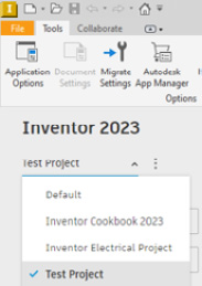
Figure 5.6: Test Project active
Select Open from the Home screen. Automatically, the Test Project workspace should open and show there are no files. We will now test whether the project is set up correctly by creating some parts and saving them in the workspace:
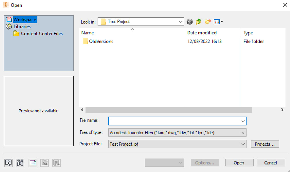
Figure 5.7: Test Project empty
- Select New, and then select Standard.ipt from the templates, followed by Create.
- Inventor will now open a new .ipt file, without creating any geometry. Now hit Save. Inventor should prompt you to save the Inventor .ipt part file in the Test Project workspace. Then, select Save again.
- Close the file.
- Select Open; your newly created .ipt file should now populate the Inventor Test Project workspace that we previously created, in step 12. This means the project file is working as intended. If desired, multiple folder structures could be created within Test Project to further organize designs and projects.
- Navigate to the Home screen and select Projects.
- Under the Projects area of Inventor, you will see there are many other options to configure for the setup of your Inventor project. We have already covered the location of the project previously in step 10 and step 11. Expand materials and appearances by selecting + next to the Material Libraries section, in the bottom half of the menu:

Figure 5.8: Inventor Test Project configurations
Here, you can change and alter what materials and appearances are available and accessible in your Inventor project. For example, you may have a specific material or appearance type for a specific customer or project. This can be loaded here.
The libraries area is where you can add paths for different folders that are not in the workspace. These could be stored on a server or network, outside of your machine. You can create paths to libraries by right-clicking on Libraries and selecting Add Path. This would allow Inventor to access these library paths and folders within them if required, even though they are not part of your workspace for this project.
Frequently Used Subfolders is for storing links to folders that you use regularly as part of the project. The subfolders act in a similar way to bookmarking a tab within an internet browser. We will now create a Frequently Used Subfolders link.
- To begin, we will create a folder within the Test Project workspace. In the Windows browser, navigate to the C: drive, and then select the Test Project folder. Right-click and select Create a New Folder. Call this folder Project 1.
- Within the Inventor project, right-click on Frequently Used Subfolders and select Add Path:

Figure 5.9: Frequently Used Subfolders
- Select the Browse button and then the Project 1 folder previously created. Type Project 1 in the text field where Folder is set as default, as shown in Figure 5.10

Figure 5.10: Project 1 typed in the folder text field
- Now, if you select Open In Inventor, you will see your subfolder link displayed on the left-hand side, as shown in Figure 5.11:

Figure 5.11: The Project 1 subfolder created and displayed
You have now created a new project file, tested it, and set up a frequently used subfolder.
Managing the Content Center
In this recipe, you will learn how to manage the Content Center as part of your Inventor project. You will also learn its configuration and setup.
Getting ready
You will not need any practice files for this recipe. You will need to ensure you have completed the previous recipe, How to create and manage an Inventor .ipj project file, as we will be using the Test Project.ipj file.
How to do it…
The Content Center is a repository of standard nuts, bolts, washers, fasteners, structural members, and more that come as standard with Inventor 2023. The Content Center allows you to pull in existing standard design and manufacturing components and use them within your designs. It is important that, along with the Styles and Standards library, this is set up correctly as part of an Inventor project file:
- From the Inventor Home screen, ensure that Test Project is the active project.
- Expand + next to Folder Options:

Figure 5.12: Folder Options expanded in Test Project
Folder Options is where you can tell Inventor where your Design Data and Templates folders will be stored and where you want your Content Center Files folder to be. By default, they are set to Default. If you are working in a collaborative environment, you must not leave Content Center Files as Default. If this is left as Default, when you use the Content Center and place a nut or bolt from this into your design, it will save this into your MyDocuments folder on your machine. This means that others who require the specific content will not be able to access this from the library. We will now set this up as if we are working in the aforementioned collaborative environment.
- Navigate using the Windows browser to the Test Project workspace on the C: drive. In reality, this would be a network drive.
- Create a folder at this level (as shown in Figure 5.13) called Content Center:
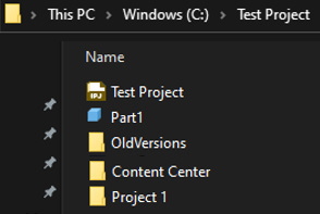
Figure 5.13: Content Center folder created
- Navigate back to the Inventor project window, right-click Content Center on Folder Options, and select Edit. Then, click Browse, select your newly created Content Center folder, and then select OK:

Figure 5.14: The Content Center folder selected in Folder Options
The same can be done for Templates so that everyone on a network uses the same templates for parts, assemblies, and drawings. This is important to set up, as without this, there are no centralized styles, templates, or standards in an organization.
We will now configure the Content Center so that we can filter specific Content Center libraries that we want to use. Some users will prefer to have access to the whole Content Center, but other organizations may only want to work with certain standards and, therefore, require the Content Center libraries to be filtered.
- Select the Configure Content Center Libraries button shown in Figure 5.15:
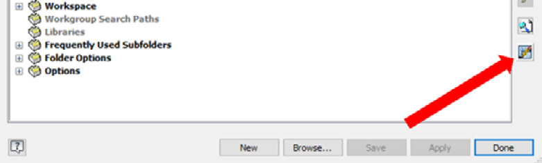
Figure 5.15: The Configure Content Center Libraries button
- You can now pick and choose what Content Center libraries are available within the project. To deselect a standard library, remove the tick from the tick box. In this example, deselect Inventor DIN from the list, as per Figure 5.16. Then, select OK:

Figure 5.16: Inventor DIN content deselected
The next aspect of the Content Center is how to create your own libraries and publish them to the Content Center.
- Select the Configure Content Center Libraries button. Then, select the Create Library button in the bottom right of the menu as shown in Figure 5.17:

Figure 5.17: The Create Library button
We must now name the library. Call this Test Library and select OK. If you are presented with an Attempt to write a read-only database error, close Inventor and then start it again using Run as Administrator from Windows, and then repeat step 8.
- A read/write test library is now created in the Content Center library for Test Project. Select OK.
- Select Done, and then Save. Select Yes to overwrite the project.
- We will now take an existing Content Center component, edit it, and save it in our new Test Library for future use. Create a new Standard Assembly.iam file.
- In the assembly file now open, select the Manage tab, and then Editor.
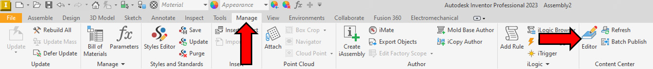
Figure 5.18: The Content Center Editor button
- Select the filter icon and then ISO as the standard to view:

Figure 5.19: The Content Center Editor – filtering the ISO standard content
- In the Content Center Category View pane on the left, select Fasteners, then Bolts, and then Countersunk. Hover over the ISO 10642 bolt, right-click, and select Save Copy As…:
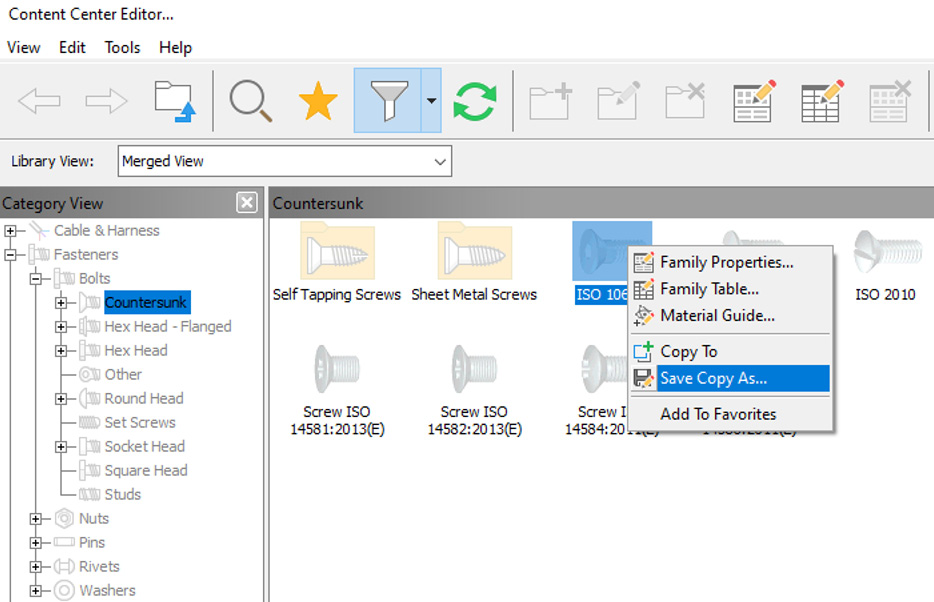
Figure 5.20: Selecting a fastener to create a copy of to edit
- In the Save Copy As window, ensure that the library to copy to is Test Library and that Independent family is checked. Change Copy of in the Family Name and Family Description fields to TP (for Test Project). Select Review:
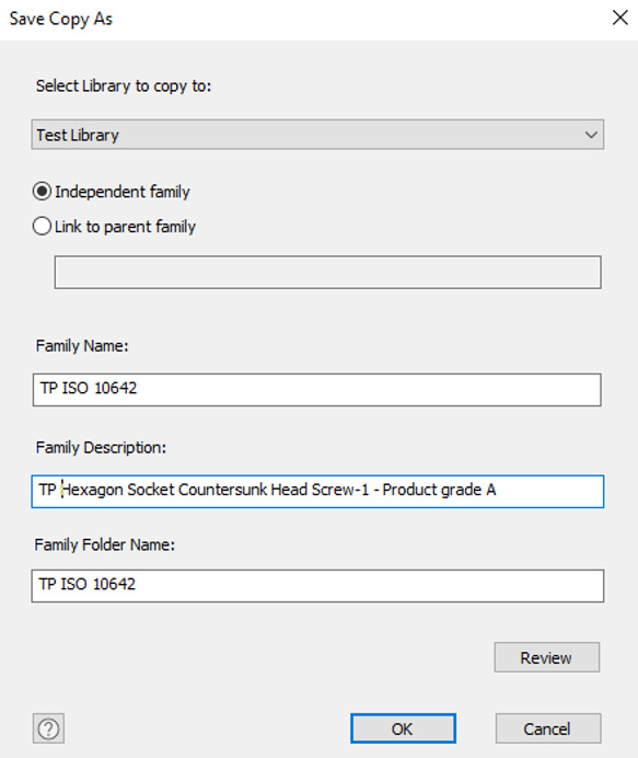
Figure 5.21: Changes to be made in the Save Copy As window

Figure 5.22: Changes made to the File Name and Part Number cells
- Select OK, and OK again.
- In the Library View dropdown, pick the Test Library option. The copied TP ISO 10642 part should now be visible in this library. We now need to edit this Content Center part, as shown in Figure 5.23:

Figure 5.23: The new Content Center library active, with the copied ISO 10642 part included
- Right-click on TP ISO 10642 and select Family Properties. Change Standards Organization from ISO to TP. Select Apply, followed by OK.
- Right-click the drop-down arrow next to the filter icon and select Add/Edit Filters…:

Figure 5.24: Add/Edit Filters… selected from the filter icon
- Select Add and create a new filter called TP. Deselect all ticked boxes in the middle and right sections of the window, except for the TP option, as shown in Figure 5.25. Select Apply and OK to complete:

Figure 5.25: TP filter created and TP selected as the standard to view in this filter
- Navigate back to TP ISO 10642. Right-click on it and select Family Table…. We will now configure the new option within our custom content fastener:

Figure 5.26: Family Table… selected
- This opens the various options for this specific piece of content. In this case, we will make a new option or variant in the M3 class. We will create an option for an M3 bolt that is 3 X 8.5, which currently is not available.
Select Row 1. Right-click and select Copy.
- Right-click and select Add Row. Then, right-click on the newly added row and select Paste.
- Navigate to Bolt Length on the newly created row and change the length from 8 mm to 8.5 mm:

Figure 5.27: Bolt length changed to 8.5 mm
- Select OK to complete. This now publishes your new Content Center part to your custom Content Center library.
- Close the Content Center window and navigate back to your assembly file. Select the Assemble tab, then Place, followed by Place from Content Center:
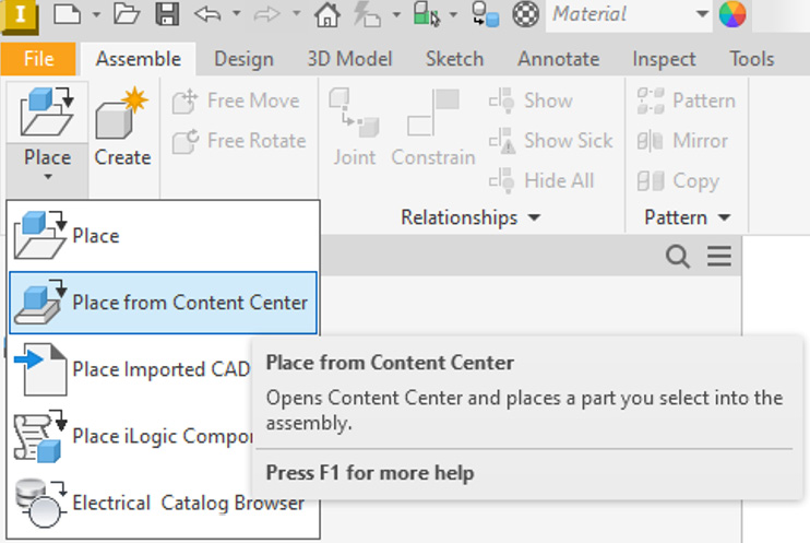
Figure 5.28: Place from Content Center
- Select the TP ISO 10642 fastener and select OK. On the import options, you will see 8.5 mm is now available to pick as a configuration for an M3 bolt type. Select 8.5 mm under Bolt Length. Then, select OK to place this from the TP Content Center:

Figure 5.29: M3 x 8.5mm TP ISO 10642 selected
- The custom Content Center item is imported into your assembly model.
You have successfully configured a custom Content Center library and created and published new custom content to it, for use in future designs. If you navigate to the Content Center folder in the C: drive, you will see that the M3x8.5.ipt file is created inside this folder.
Style and Standard Editor – creating and editing templates
In this recipe, you will learn how to use the Style and Standard Editor to edit a drawing template and configure style libraries so that a template is accessible to others in your organization.
A style library contains the definition of individual style types. When you apply a style to an object in a document, the attributes of the style are retrieved from the style library. Inventor gives you the ability to copy and then edit existing style libraries to suit your individual or organizational requirements. This could be, for example, the way that a drawing template is configured for a company or a material list that needs to be accessible to all team members.
By default, all styles in the style library associated with the active drafting standard are available to format objects in documents. Your style libraries should be managed by your CAD administrator or engineering manager, as it should not be something that all users have read/write access to. This is because, without these securities, it is harder to enforce specific standards and templates.
You can use a single global library so that all designers use the same styles, or you can specify a library for a specific set of design files or each project.
The main reasons why you may want to use the Style and Standard Editor are as follows:
- You work with large assemblies and need to share style information between multiple documents
- Collaboration in a workgroup/company or project that needs a common source of styles throughout
- The enforcement of internal CAD standards and best practices within an organization
In this recipe, we will create a new Inventor style library for an Inventor drawing template and enforce this across a project. There are countless changes and customizations that can be applied to a drawing template. However, in this recipe, we will make some simple changes. A comprehensive list of what is possible to change from within the Style Editor can be found here: https://knowledge.autodesk.com/support/inventor/learn-explore/caas/CloudHelp/cloudhelp/2019/ENU/Inventor-Help/files/GUID-33EE57FB-9343-4647-83F0-B737F80B7E9C-htm.html.
Getting ready
You will not need any practice files for this recipe. You will need to ensure you have completed the How to create and manage an inventor .ipj project file recipe, as we will be using the Test Project.ipj file.
How to do it…
- From the Inventor Home screen, ensure that Test Project is the active project.
- Select New, and then New again. Expand en-US, select Metric Folder, and scroll down. Pick ISO.dwg as the template. Select Create.
- Select the Manage tab from the ribbon bar, and then select the Styles Editor command.
The Styles Editor will now open. Here, you can make changes to settings that are displayed in your drawing template standard. This could be dimension text, leader type, border thickness, and more – the list of customizations is extensive. This is all controlled from the Style and Standards Editor menu:

Figure 5.30: Style and Standard Editor open
If changes were made from this menu now, the styles and standards would be updated for this local document, but they would not be transferred to the global style and standard libraries. This would mean that every time a new drawing is created, these settings would have to be manually applied again. Fortunately, there is a way to prevent this and enforce our new style customizations across all users from our global style manager.
- Close the Inventor drawing previously opened in step 2 and navigate back to the Inventor Home screen.
- Open the project settings with Test Project.ipj active.
- Expand Folder Options with +:

Figure 5.31: Folder Options expanded in Projects
- Folder Options is still in the Default setting. This means it is using the standard default global style manager settings. We will now create a copy of the Design Data folder and then place this into our project workspace.
It is important to make a copy of the Design Data folder, as if we change the master default settings for Inventor, these cannot be undone!
In the Windows browser, navigate to Windows (C:) | Users | Public | Public Documents | Autodesk Inventor 2023.
- Select the Design Data and Templates folders, right-click, and select Copy.
- Navigate to the project workspace location at Windows (C:) | Test Project.
- Right-click anywhere and paste the files into the Test Project folder:
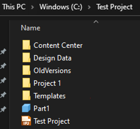
Figure 5.32: Design Data and Templates copied into the Test Project workspace
- Navigate back to the Inventor Home screen and open the project settings for Test Project.ipj.
- Expand Folder Options if these are not expanded. Right-click on Templates and select Edit. Browse and select the Templates folder we just copied into the workspace.
- Right-click on Design Data and select Edit. Browse and select the Design Data folder we just copied into the workspace.
- Right-click on Use Style Library = Read Only and select Read-Write. This now enables us to sync local style changes to our new global style library within the project workspace.
- Select Done and then Yes.
- Select Open in Inventor, and then select Templates. Browse through en-US and Metric, and select ISO.dwg. This is the base template we will use for this example. You should always use the default template that is most aligned with your organization’s standards from the beginning. Select Open.
- We can now start to make all the changes to the template that we want to be global – for example, the drawing border and title block dimensions. In this example, we will make changes to the border color, Dimension Style, and edit the BOM columns on the drawing sheet. These are features we want to be global and always present on our drawing template.
Select the Manage tab, followed by Styles Editor.
- Navigate to the Layers area of Style and Standard Editor, expand Layers, and select Border (ISO):
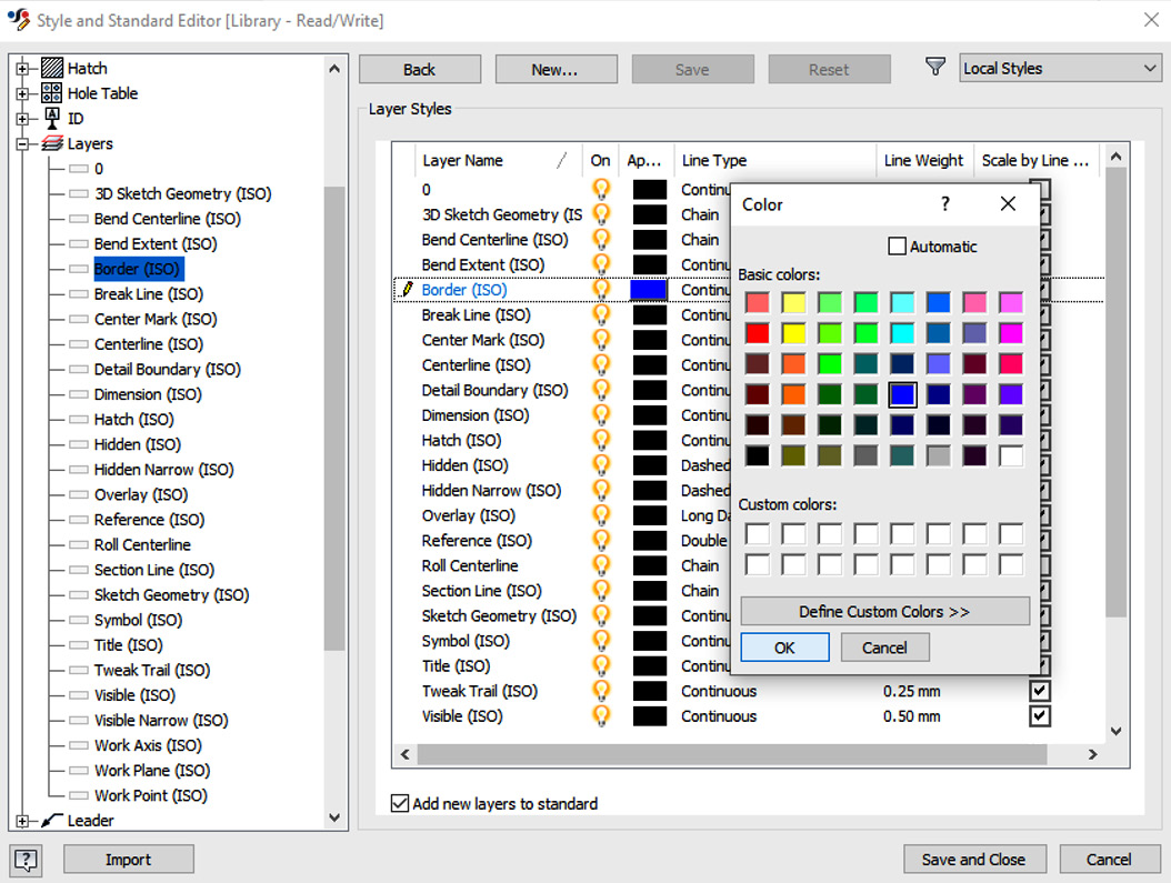
Figure 5.33: Layers expanded and Border ISO selected
- In the Layer Styles area, under Appearance, select the black square next to Border (ISO). In the color swatch, select dark blue. Select OK. Then, select Save & Close. This will change the border color to blue.
- We will now change Dimension Style. Select the Manage tab, followed by Styles Editor.
- Expand the Dimension options and select Default (ISO).
- Change Decimal Maker from Comma to Period.
- Select Display | Color and change it to red.
- Select Text, and then change the size from 3.50 mm to 4.50 mm. Select Save:

Figure 5.34: Editing the Dimension display from the Style and Standard Editor
- We will now make changes to the BOM configuration. Expand Parts List.
- Select Material List (ISO), and then select Column Chooser. Browse to MASS and select Add ->. Then, select OK:

Figure 5.35: BOM Column Chooser
- Select Save, followed by Close.
- After updating our changes to the border, dimensions, and BOM, we must now confirm this in the global style library. On the Manage tab, next to the Styles Editor command, select Save, as shown in Figure 5.36:
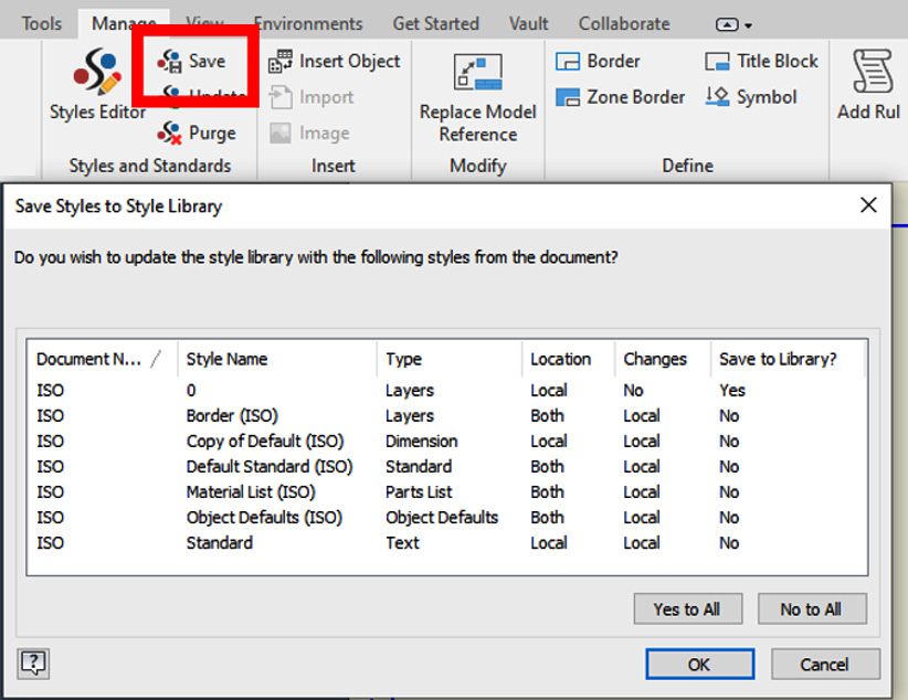
Figure 5.36: The Save icon in the Styles and Standards area
- Accept any migration that Inventor prompts, and then select Yes to All in the next menu. This informs you that your local style has the following differences from the global style and standard library. Then, select OK and Yes.
- Close the drawing. You do not need to save any changes, as we have already saved these to the global styles and standards.
- Select New, and browse the ISO.dwg template. Create a new drawing from this template. Select OK on any message that appears.
- Go to Manage, and hit Save in the Styles and Standards area.
- Select File | Save Copy as Template, and name your template TP Template. Select Save.
- Close the drawing.
- Now, select New Drawing in Inventor. TP Template will be available to use with all styles and standards we applied and created in this recipe, as shown in Figure 5.37:

Figure 5.37: TP Template available
You have created and configured a new template for use in Inventor, using the style and standard libraries.
Collaborating with shared views
In this recipe, you will learn how to create a shared view of your Inventor model so that you can send this to collaborators on a project.
Shared views are used to create a read-only, visual representation of your model or design online, via the cloud. Inventor will generate a link that will allow anyone with access to view and comment on the shared view without the need to install an Autodesk product. From within Inventor, you can manage and act on the feedback supplied.
This is especially useful for communicating with internal and external stakeholders in a project, who are outside of the design department or do not have access to Autodesk CAD products such as Inventor.
Getting ready
You will need to access the Chapter 5 folder within the Inventor 2023 Cookbook folder. You will also need to ensure that Inventor Cookbook 2023.ipj is set as the active Inventor project. You will also need access to your email, and it would be beneficial to have a mobile device that can access your email account also.
How to do it…
- Ensure that your Inventor project is set to Inventor Cookbook 2023.ipj.
- Select Open, and navigate to the Chapter 5 folder.
- Select the V6 Engine folder. Then, select the V6 Engine.iam assembly file. After that, select Open.
- The assembly opens as normal in Inventor. We will now create and upload a read-only version of this into the Autodesk cloud, and grant access via a link we can share in an email. This means the recipient will be able to view and see this model on a PC or mobile/tablet device.
Navigate to the Collaborate tab. Then, select Shared Views:
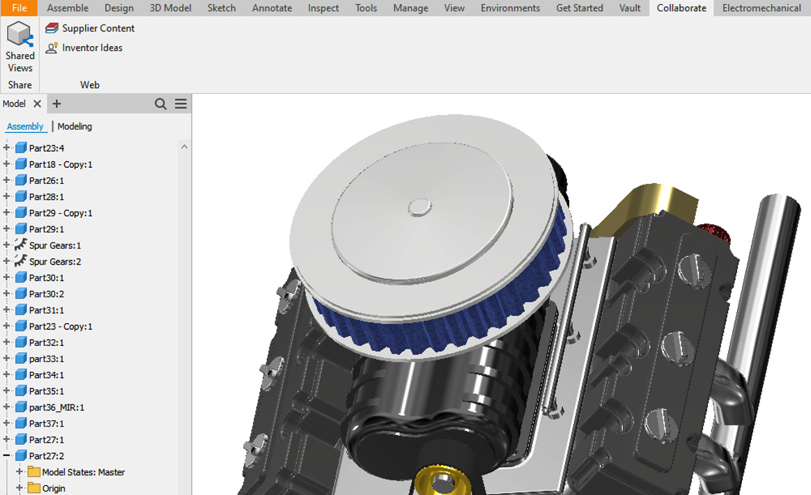
Figure 5.38: The Shared Views command shown in the Collaborate tab
- Select Shared Views. The Shared Views tab will open on the right of Inventor. Select New Shared View. You are then prompted to name the viewable active file; leave this as default for now. Renaming this does not change the copy on your local machine.
- Untick Hide component names and Hide part properties. Then, select Share.
- The shared view of this assembly will now be created, once successfully uploaded. Select View in Browser. This is what the recipient will see once a link has been sent and opened of the design. The view changes slightly on a mobile device.
- AUTODESK VIEWER now loads in your web browser. An email is automatically generated to your email address, registered to your Autodesk account, telling you that your shared view is ready. We can now begin to manipulate and view the read-only version of the CAD model.
Within the browser, there are multiple functions we can use:

Figure 5.39: AUTODESK VIEWER displaying the shared view in the cloud, created in the browser
Using the commands along the bottom of the browser, we can orbit, pan, zoom, and take measurements.
Next, select Explode.
- Drag the blue dot on the slider to explode and reassemble the whole assembly:
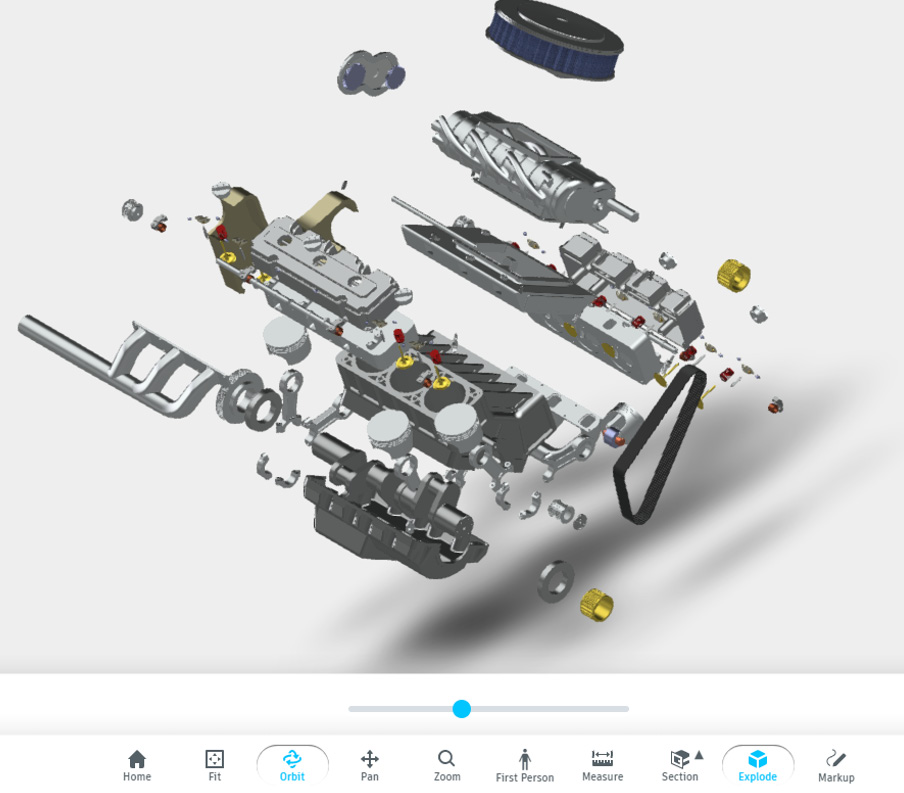
Figure 5.40: The Explode function applied to the model
- Select the Model browser in the viewer. From here, you can examine each part that makes up the assembly and hide components. You can also change the transparency of parts:
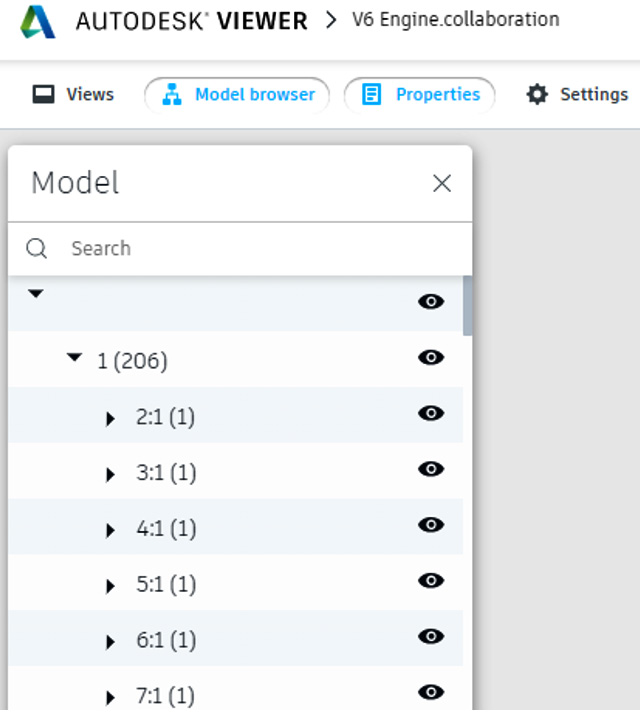
Figure 5.41: The Model browser in AUTODESK VIEWER
- We will now write a comment back to the designer. In this case, we are simulating what a stakeholder or customer would do if the shareable link had been sent to them. For this, select Markup from the bottom toolbar.
- With Pencil selected, click and hold to draw a circle around a component in the exploded view of the V6 engine, as shown in Figure 5.42:

Figure 5.42: Markup applied
- Select Arrow and create an arrow from the circle, by clicking and dragging:

Figure 5.43: An arrow drawn from markup
- Select Text, and click in the space near the head of the arrow. Type TEST COMMENT and click again to complete:

Figure 5.44: TEST COMMENT applied
- At the top right of AUTODESK VIEWER, hit Save to complete the markup.
The history of comments and changes made in the viewer is now shown.
- Close AUTODESK VIEWER.
- Navigate back to Inventor and the V6 Engine Inventor.iam assembly. Hit the Refresh symbol in the Shared Views tab.
- The comment we made in the browser has appeared in the shared view area on the right of the screen, and we can see and act on the design feedback:

Figure 5.45: The comment visible in Autodesk Inventor
Comments can also be replied to so the recipient will receive this the next time they open the shareable link.
- Now, we will share the design via email. Select Copy link from the Shared Views upload:

Figure 5.46: Copy link
- The link is copied to the clipboard. Open your email, and paste the link into a new email. Send this email to yourself.
- Open the email on your mobile device, and experiment with the shared views on it.
We have now used shared views to send a read-only viewable file from the cloud, via a link, that can be viewed on a PC or mobile device without Inventor software. We have also learned how to manipulate the model in this interface, and add/receive feedback, markups, and comments.
Collaborating and sharing designs with Pack and Go
In this recipe, you will learn how to use Pack and Go functionality to share a design or project with someone else.
Pack and Go is used to archive a file structure, share or copy a complete set of design files while retaining links to referenced files, or isolate a group of files. It can be used to share data externally as well as internally within your company. Note that recipients must have a valid Autodesk product to open their files once a Pack and Go package is received.
Pack and Go does not create a live link for multiple stakeholders to make edits too but instead sends a copy of data on your local machine as a package. If collaboration on the same files is required within the same organization, then using Autodesk Vault with Inventor is highly recommended for this and is much more efficient.
When Pack and Go is initiated on a file or multiple files, these files are copied to the location specified by the user, and the source files are neither changed nor removed.
Pack and Go will only work with fully resolved files using the current project file.
There are a few ways in which a Pack and Go operation can be initiated:
- From within Autodesk Inventor
- From Microsoft Windows’ File Explorer
- Using the Design Assistant outside of Inventor
Getting ready
In this recipe, we will create a Pack and Go of an assembly from within Inventor. You will need access to the Gearbox assembly.iam file located in the Chapter 5 folder, within the Inventor Cookbook 2023 folder.
How to do it…
Within Inventor, we will first open the top-level assembly that we want to share:
- With Autodesk Inventor open, select Open and browse the following location for the practice file: the Inventor Cookbook 2023 folder | the Chapter 5 folder | the Gearbox folder, and open Gearbox.iam.
- Select File | Save As | Pack and Go:

Figure 5.47: Pack and Go selected from within Inventor
- We now need to specify the destination folder for this Pack and Go. In this case, select the browse button to the right of the destination entry, and browse and select Desktop:

Figure 5.48: Browsing for the destination folder
- We will leave other options as default to keep the folder hierarchy, and to include all linked files.
What will be necessary is to package the Pack and Go as a .zip folder. This makes sharing the folder and the design much easier, especially over email or a cloud-sharing platform.
Select the Package as .zip.
- Select the following: Skip Libraries | Skip Styles | Skip Templates.
- Select Search Now, as shown in Figure 5.49:

Figure 5.49: The Search Now functionality in Pack and Go
This will ensure that all necessary files are selected for the Pack and Go operation.
- Once completed, the files found will be listed in the bottom half of the menu. Proceed to select the second Search Now option to search for any referenced files.
- In this instance, no external files are found in relation to this assembly, as shown in Figure 5.50. Select X to complete:

Figure 5.50: No Pack and Go reference files detected
- Select Start in the menu. This will initiate the Pack and Go.
- Once the progress bar has completed, select X to close the Pack and Go menu.
- Browse to your desktop.
- Locate the Pack and Go files on your desktop ready to be shared.
You have now completed a Pack and Go operation of an assembly from within Inventor so that files can be shared with another user of it.
Model credits
The model credits for this chapter are as follows:
- V6 Twin Turbo Engine + supercharger (by Lê Thảo) https://grabcad.com/library/v6-twin-turbo-engine-supercharger-1/details?folder_id=9240197
- Gearbox-ST4- 200- PAM100112B5 (by Saeed azizi) https://grabcad.com/library/gearbox-st4-200-pam100112b5-1/details?folder_id=11290519