
13
Inventor Professional 2023 – What’s New?
Inventor 2023 was released in March 2022 and, as always, Autodesk has made many performance, automation, and core modeling workflow improvements on the previous release. Many of the additional features and enhancements have been driven by customer feedback and ideas from the Inventor forums community. The enhancements of version 2023 help streamline the design process and reduce repetition. Many of the key improvements have been made around connected workflows and interoperability with other products in the Autodesk portfolio, such as Fusion 360 and Revit interoperability. The focus on this aspect shows that it is now more common for designers and engineers to work on more collaborative and complex projects that require seamless interaction and the interoperability of file types and workflows in CAD/CAM packages.
You can find the full Inventor 2023 release notes here: https://help.autodesk.com/view/INVNTOR/2023/ENU/?guid=Inventor_ReleaseNotes_release_notes_html
If you are thinking about moving to Inventor 2023, the system requirements can be found here: https://knowledge.autodesk.com/support/inventor/learn-explore/caas/sfdcarticles/sfdcarticles/System-requirements-for-Autodesk-Inventor-2023.html
In this chapter, you will learn about the following:
- General enhancements to Inventor 2023
- Interoperability between Fusion 360, Revit, and more
- Sketch enhancements
- Part enhancements
- Assembly and presentation enhancements
- Drawing enhancements
Technical requirements
You can access the practice files, where applicable, from the Inventor Cookbook 2023 > Chapter 13 folder.
Important note
This chapter will not have a recipe for each enhancement/new feature or change, but wherever appropriate, these have been incorporated and practice files have been made available.
Also, this chapter does not include future bug fixes or updates to the 2023 post-release version.
General enhancements to Inventor 2023
This section details general enhancements that have been made to version 2023.
New Home screen: Home replaces My Home
One of the most graphically dramatic differences between version 2022 and 2023, is the new Home screen. This has replaced the previous My Home screen. Upon opening Inventor 2023, you will be presented with a new graphical interface to start the creation of or open existing files.
The redesigned Home page has a design and layout that is more consistent with other Autodesk products, such as AutoCAD or Fusion 360, providing a more consistent and unified theme.
The new arrangement and features of the Home screen are as follows:
- The left panel offers access to select and create projects or to start or open files
- Recent documents can be displayed as thumbnails or as a list, similar to the 2022 release, but with a refreshed look and feel
Figure 13.1 shows the new Home screen:

Figure 13.1: New Inventor 2023 Home screen
The new design of the Home page eliminates many of the duplicated functions found in the 2022 release and makes the process of accessing data and files much easier and more fluid.
Figure 13.2 shows the list option selected for preview files on the Home screen:

Figure 13.2: Home screen shown in list view
You can also pin files of interest, and refine the Sort by categories when viewing files.
GPU Ray Tracing display
Inventor 2023 introduces a new display option that takes advantage of new developments in graphics cards. GPU Ray Tracing, at the time of writing, is currently in a pre-release state but is available in Inventor now. GPU Ray Tracing provides real-time graphics rendering. In previous releases of Inventor, the only way to do this was by selecting the Ray Tracing display option, which would produce ray tracing via the CPU. The GPU Ray Tracing functionality allows you to use either the CPU or GPU for ray tracing. The use of the GPU should result in a higher-quality render in almost all cases.
The performance of GPU Ray Tracing depends heavily on the GPU within your machine, so your results may vary dramatically. Before using GPU Ray Tracing, it is important to check that your GPU is compatible with and supported by Inventor 2023.
The following recipe will demonstrate how to access GPU Ray Tracing.
How to do it
To begin this recipe, you will need to have Inventor 2023 installed. You will need to navigate to Inventor Cookbook 2023 > Chapter 13 and open Bomba KSB ETA 80-20.ipt. Then, follow these steps:
- With the Bomba KSB ETA 80-20.ipt part open, select the Tools tab. Then, select Application Options.
- Then select the Hardware tab, followed by Enable Viewport GPU Ray Tracing (Pre-release). Figure 13.3 shows these options:
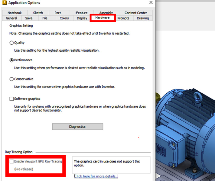
Figure 13.3: How to access GPU Ray Tracing
- Close Application Options. Select the View tab. In the Appearance panel, change Visual Style to Realistic.
- Select Ray Tracing. Configure your Ray Tracing requirements and begin Ray Tracing. If you don’t have a compatible GPU, Inventor will still carry out ray tracing but using your CPU.
You have configured Inventor 2023 to utilize GPU Ray Tracing and create a real-time optimized render.
iLogic
A small iLogic enhancement has been made in this release. The custom command for an External Rule or Global Form can now be applied to the ribbon for easier access and execution.
Improved Free Orbit
As in previous releases of Inventor, you can hold Shift and scroll the mouse wheel to perform a free orbit around a model. In version 2023, this has been further enhanced by what is visible to the user in the Graphics Window, as follows:
- If the full model is in view, then the default Pivot Point is the model’s center
- If the model is partially in view, then the central Pivot Point will snap to the nearest edge, face, or vertex
- If the model is outside the view, then the Pivot Point will default to the cursor location
These enhancements make Free Orbit more stable and easier to navigate.
[Primary] replaces Master in model states
For model states, view representations, and positional representations, the term Master has been removed. It has been replaced with [Primary]. This is to minimize conflict with potential part names featuring Primary.
Existing iLogic code that states that Master referring to master model states, for example, will not be affected by the change. The mechanics of model states, view representations, and positional representations will not be affected by this change.
For more on model states, see Chapter 7, Model and Assembly Simplification with Simplify, Derive, and Model States.
The Alt + Q new keyboard shortcut for Annotate
Holding Alt + Q is a new keyboard shortcut to the Annotate tab.
Performance enhancements and Express Mode
Inventor 2023 promises to bring substantial performance enhancements to both Thread display in assemblies, and iFeature performance with Punch Tools.
The Express Mode has been further improved – when component visibility is changed, performance is improved in Express Mode.
Express Mode is ideal for large assemblies and, when enabled, models will open much faster by loading only component-cached graphics into memory. Express Mode can be located via the Application Options | Assembly tab.
Interoperability between Fusion 360, Revit, and more
Inventor 2023 brings significant changes and enhancements to workflows and interoperability options, specifically with Fusion 360 and Revit. This makes for more seamless workflows when working with files in multiple products within the Autodesk portfolio and adds much more flexibility.
Fusion 360 tools
Within Inventor, there are now more options in the Fusion 360 tab. These tools allow you to copy an Inventor design and upload it automatically to Fusion 360. Note that to use this feature, you must either have a standalone license of Fusion 360 installed and active or have Fusion 360 installed from your Product Design & MFG Collection license.
Figure 13.4 shows the new look and tools of the Fusion 360 tab:

Figure 13.4: Fusion 360 tools in Inventor
When using these tools, you have the option of starting the Fusion 360 workspace directly from Inventor. The Fusion Modeling command was previously known as Send to Fusion 360, and will take your Inventor model directly into the Fusion 360 Design workspace. Additionally, options in version 2023 enable a quick transition to other Fusion 360 workspaces, such as Simulation.
To use this new feature, simply open the Inventor file you wish to work with in Fusion 360, and then select the Fusion 360 workspace you want to work in. Inventor components selected are then derived to a single .ipt file, copied to Fusion Team, and then opened in the selected workspace within Fusion 360.
This makes transitioning from Inventor to Fusion 360 for specific tasks and workflows much easier and requires fewer steps than previous versions. The process is bi-directional to a degree – using the existing AnyCAD feature, you are also able to directly open Fusion 360 files within Inventor. This update enables Inventor users to get access to great cloud features such as Simulation, Generative Design, and cloud Rendering that are only found in Fusion 360.
Data exchange and interoperability enhancements for Revit and Inventor
Data exchange in Inventor is a new way to share specified subsets of Revit data with Inventor users. It is becoming increasingly common for manufacturers to work in close collaboration with the architectural stakeholders of a project. Data exchange makes this process much more efficient.
Data exchange enables you to view and filter data, and then make changes to the data in software such as Inventor.
It’s important to note that Revit files can be huge in file size. Having a good understanding of the project and condensing the geometry in a data exchange to what is necessary for the Inventor user is essential.
The capability of referencing Revit data in Inventor utilizes a pre-installed Revit component. This must be the same release version as the Inventor version installed. Normally, the Revit component will install automatically when Inventor is installed. But if this was de-selected during the installation processl, it can also be manually added.
Once a Revit component is activated with a command, if the Revit component is not installed, then the Inventor command is canceled, and the Revit component is installed in the background automatically. Once installed, the Revit component allows the efficient importing of Inventor files.
Sketch enhancements
This release features a few sketch-based enhancements that focus on repairing broken projected geometry and additional options for accessing iProperties in sketch-based text or 3D Annotations.
Fixing broken projected geometry
When modeling in Inventor, geometry can sometimes break due to associated sketches, dimensions, or geometry being deleted or changed. This often occurs when critical referenced geometry in the model browser has been changed or deleted. Associated sketches or geometry can then become broken or orphaned. Previously, this was a much more manual task to address, but now you can go to those sketches and repair or delete the broken projections. This is advantageous, as sometimes the geometry that needs to be changed is difficult to locate or identify.
The new workflow is to edit the sketch with the broken geometry – right-click the Sketch Browser node and select Broken Projections. This highlights the problematic geometry so that it can be deleted.
Model sketching and the annotating text enhancement
When applying sketch text or applying a general note with 3D annotations, Standard iProperties and Custom iProperties, if present in the model, standard and custom iProperties can now all be accessed from the active part file, within the Format Text box. This function is not available in the assembly environment. Figure 13.5 shows the dropdown available in the Format Text options to access iProperties:

Figure 13.5: Standard iProperties accessed in either sketch text or 3D general annotation
This makes it easier to access and reference custom or standard iProperties from within sketch text or 3D general annotations.
The new link sketch format for sketch blocks
The new Link sketch formatting from source component option in Derive, enables the control of sketch blocks in the derived part, if the source sketch geometry is changed.
Part enhancements
3D annotations, sheet metal, and model-based definitions are areas that have had lots of improvements in the 2023 release. This section details what changes have been made to the Part environment of Inventor.
Sheet metal extended browser information
Version 2023 brings some new changes and enhancements to the Sheet Metal Part environment. The first is an Extended Information in Browser Enabled for Multiple Commands. This enables users to get more information about a sheet metal part or operation from the model browser.
To access the extended information, with a sheet metal part open, select Application Options | the Parts tab, then select Show Extended Names.
Figure 13.6 shows an example of the Extended Information in Browser Enabled for Multiple Commands active:
Figure 13.6: Extended information in browser enabled
The extended information in the browser feature makes it much easier to assess and differentiate between different types of sheet metal features within a part.
The Sheet Metal Template option
You can now access a new Sheet Metal Template option via the Tools | Document Settings | Modeling tab, then select Make Components Options to select or browse to the template used to create new Sheet Metal part files.
New Sheet Metal Mark command for engraving/etching features
This new command enables users to easily create and apply engraving or etching features to solid features of a model.
In this recipe, you will learn how to use the new Mark command.
How to do it
To begin this recipe, you will need to have Inventor 2023 installed. You will need to navigate to Inventor Cookbook 2023 | Chapter 13, open Mark.ipt, and follow these steps:
- In the Sheet Metal tab, navigate to the Modify panel in the ribbon and select Mark:

Figure 13.7: New Mark command
- Select the Inventor 2023 text on the face of the part.
- Mark Surface or Mark Through can now be selected. Select Mark Surface.
- Select OK. The text is marked on the face of the sheet metal part of Mark.ipt:

Figure 13.8: New Mark command used to etch text to the surface of a Sheet Metal part
You have now used the new Mark command to etch text into a sheet metal face.
3D annotation Datum Target command added
A Datum Target command has been added to the 3D General Annotations and Styles commands, as shown in Figure 13.9:

Figure 13.9: New Datum Target 3D annotation command
This enables you to establish datums on irregular surfaces. Point, Circle, and Rectangle datum targets can now be specified on a model as a 3D Model Based Definition.
Tolerance feature enhancements
3D model based definitions of tolerance features can now be defined on more types of geometry, such as planes, sketch points, work points, user-defined axes, and existing datum targets.
Data reference frame label selection
Data reference frame labels have changed to allow quicker and easier access to 10 selectable frame labels and an additional Custom option, as shown here:

Figure 13.10: Data reference frame label selection
If you have already placed a data reference frame label, and are about to place a duplicate, Inventor will warn you that the data reference frame label is already present in the model.
Multiple selections for 3D annotation leaders
3D annotation leaders can now be placed by selecting multiple faces or edges of a model.
Rectangular borders for 3D annotation leaders, text, and general notes can now be applied using the option in the Format Text window, as shown here:
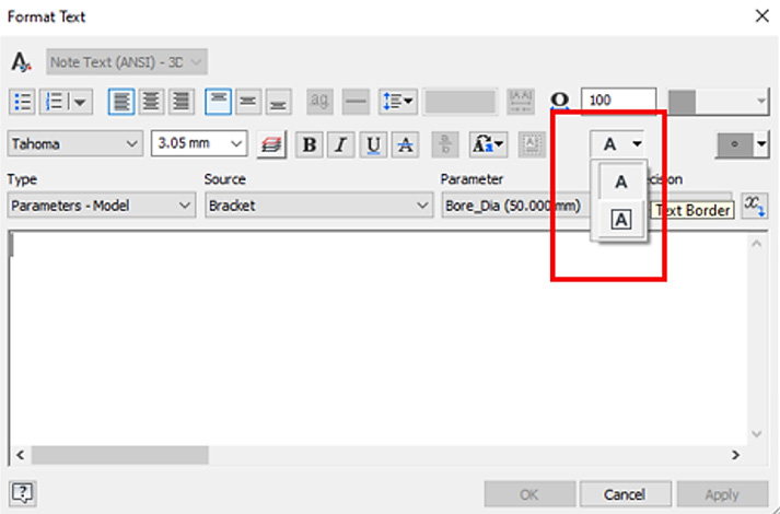
Figure 13.11: Rectangular border for 3D annotations, leaders, text, and general notes
Figure 13.11 shows where to access the rectangular border for 3D annotations, leaders, text, and general notes.
Tolerance and parameter updates to model states
The part and assembly model states now support unique tolerance settings for a model state. This means independent Tolerance values can be set in different model states of the same model.
Tolerance type options in Parameters
Within the Parameters dialogue, the Tolerance options in previous Inventor versions were limited to either Upper, Median, Nominal, or Lower. Now, by selecting a Tolerance row and selecting the pencil icon, you can access the full Tolerance dialogue:

Figure 13.12: Basic tolerance type
The Basic tolerance type has been added to the Type selection options as shown here:
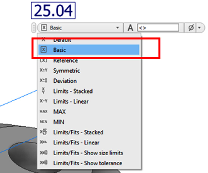
Figure 13.13: Basic tolerance type added
Tolerances can now be promoted and synchronized. The Basic Tolerance dimension is also available and accessible for 3D Annotation dimensions.
Multi-Value sort order in Parameters
For user-defined parameters, when Multi-Value is selected, you can now choose to Sort Order for the values by selecting Custom order as shown here:

Figure 13.14: Custom order, available in User Parameters for Multi-Value options
This helps prioritize options that are more frequently selected for easier access.
Fillet tolerance
When placing a fillet on a part, you can now add Tolerance values. In the Fillet command, with an edge or edges selected, right-click on the dimension value to bring up the Tolerance options, as shown here:
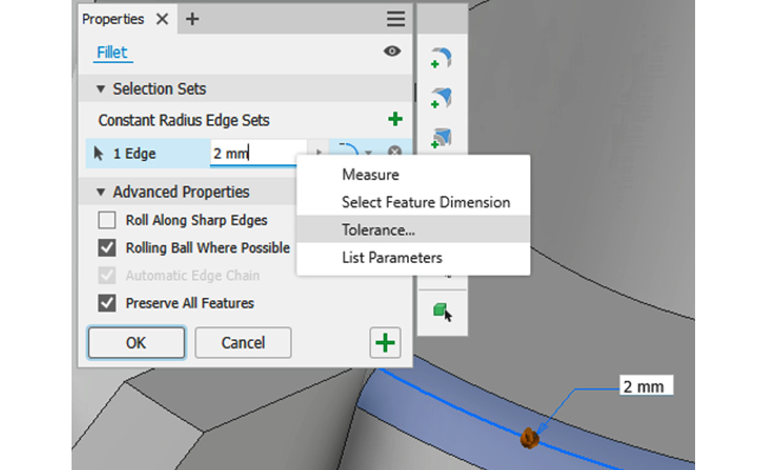
Figure 13.15: Tolerance options in Fillet
This reduces the number of clicks and operations previously required to do this.
The Relationships command for suppressed features
In the 2022 release, the Relationships command would only work for active features within a part. Now you can also run the command on suppressed features, to examine relationships between other features, as shown here:
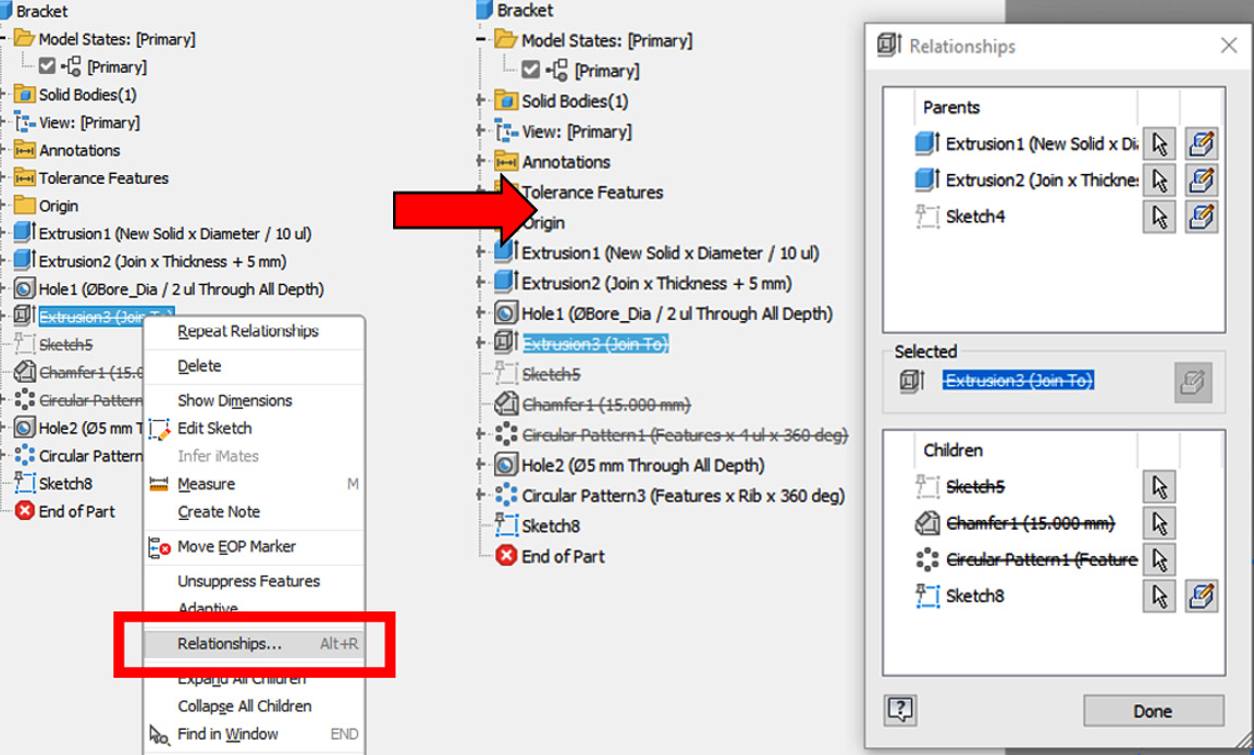
Figure 13.16: The Relationships command for suppressed features
The part enhancements are quite extensive within release 2023, particularly for the annotation and model-based definition features. The next section will detail changes, new Bill Of Material (BOM) settings, and functionality in the Assembly environment.
Assembly and presentation enhancements
This section details assembly enhancements that have been made to version 2023.
BOM setting updates
Allows for zero quantity visibility and the item number sequencing of components in BOM. Currently, if a component is suppressed in a model state, it will appear as 0 QTY in BOM. By selecting BOM Settings followed by the Enable or Disable options, Hide Suppressed Components in BOM or Renumber Items Sequentially can be selected as shown here:
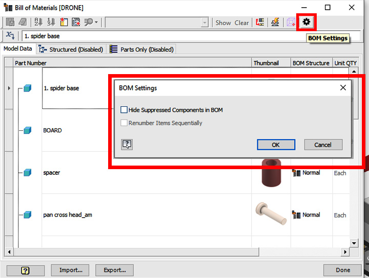
Figure 13.17: New BOM settings
Next, we will discuss changes to substitute model states.
Changes to substitute model states
Now, in version 2023, when a substitute model state is active, the following commands in the ribbon are disabled:
- Place iLogic Component
- Analyze Interference
- Activate Contact Solver
- Convert to Weldment
- Component context menu
- Demote/Promote
- Replace from Content Center
New options for Simplify
The Simplify command has been updated further to accommodate the following feature recognition options:

Figure 13.18: Pocket and Emboss visible in the Simplify command
This is to provide a clear classification of both additive and subtractive features. Pocket recognizes subtractive features, and Emboss recognizes additive features.
Constraint workflow command change
You can now suppress a constraint directly when editing it by selecting the Suppress Constraint checkbox in the Place Constraint, Edit Constraint, and iMate command dialogues.
Drawing enhancements
This section details drawing enhancements that have been made to version 2023.
Detail View drawing enhancement
When a Detail Drawing View is placed, selecting Edit Detail Properties on an existing detail section enables you to change the detail view Fence Shape option to either Circular or Rectangular, as shown here:

Figure 13.19: Detail View Fence Shape options
Figure 13.9 shows the Detail View Fence Shape options.
Model state name within drawing labels
You can now configure view labels to display a model state name in drawing views. If edits are made to the Model State, these are reflected in the view labels.
Within the Overlay View for parts, you can now also select the required model state to be shown in the view as shown here:

Figure 13.20: Model state name within drawing labels
In Figure 13.20, under the Property section of the Format Text box, you can see MODEL STATE is selected.
Remove existing sheets from new drawings
A new option, Delete all existing template sheets, has been added to the Sheet tab of the Document Settings. This will automatically remove existing sheets when a new drawing is created from a predefined sheet format.
Model credits
The model credits for this chapter are as follows:
Bomba KSB ETA 80-20 - 5CV - 1700rpm (by Jorge Omar and Ferreyra Libano): https://grabcad.com/library/bomba-ksb-eta-80-20-5cv-1700rpm-1
This brings us to the end of the book. I truly hope that you have had an enjoyable reading experience and that you have learned many new valuable skills that will aid you in your day-to-day usage of Inventor. It is my hope that these new advanced tools and techniques you have practiced using have accelerated your capabilities, broadened your knowledge, and raised your confidence in Inventor. You are now well on your way to becoming a pro!
Not every person uses Inventor the same way. Your processes and workflows are specific to you, but hopefully, the book has led you to ask questions about your workflows and techniques and has led to improvements. There is still much more to Inventor than this book covers, and I hope that some of the chapters’ topics might have sparked your curiosity and interest in new areas of the software into which you can now “deep dive” and specialize.
May your sketches be fully defined and your load times swift. All the best to you with Autodesk Inventor!