Organizations typically focus on building applications and data-driven software to harvest value from thier data. An enterprise segmentation strategy helps technical teams create isolation across networks, applications, and identity-management systems.
The previous chapter explained how to set up Identity and Access Management (IAM) with Azure Active Directory (AAD).
Software-defined networks (SDNs)
Network topologies
Segmenting subnets
Controlling routing behavior
Using gateways and firewalls
Software-Defined Networks (SDNs)

A flow diagram depicts on premises connectivity, higher reliability, and greater, inspect outgoing traffic using on premises or cloud devices, V P N gateway, express route, third part N A V, and force tunnel to on premises.
Networking decision guide
SDNs provide various options with differing prices and complexity. There are many ways to implement SDN technologies to create cloud-based virtual networks . Based on your governance requirements, you can structure the virtual networks for migration and interact with an existing IT infrastructure.
PaaS : All the PaaS products have limited built-in networking features. So, in most cases, you don’t have to specify the software-defined network to support the workload requirements.
Cloud-native : A cloud-native architecture supports cloud-based workloads using the virtual network that’s built on top of the default software-defined networking capabilities. See Figure 3-2.

A model diagram represents the azure directory, internet, azure D N S, the app service plan, app service web app, azure S Q L database, logical server, storage account of cloud native architecture.
Cloud-native architecture
Cloud Dematerialized Zone (DMZ) : This cloud DMZ has limited connectivity between the on-premises and cloud networks, secured through a network implementation that controls the traffic between the environments. See Figure 3-3.

A block diagram represents the on premises network, I P Sec or I K E tunnel, hub virtual network, peered virtual networks, and spoke virtual network of the cloud D M Z.
Cloud DMZ
Hybrid : A hybrid cloud architecture allows virtual networks in the trusted cloud environments to access the on-premises resources as well as the cloud resources. See Figure 3-4.

A flow diagram represents the on premises network to local edge routers, express route circuit, and Microsoft edge routers to gateway subnet of express route gateway of the hybrid virtual network.
Hybrid Virtual Network
Hub and spoke : This architecture centrally manages external connectivity and shared services to overcome potential subscription limits. See Figure 3-5.

A model diagram represents the on premises, hub virtual, peered virtual, and spoke virtual networks including a virtual machine, azure bastion, azure firewall, V P N gateway, and azure monitor.
Hub and spoke model
Hub and spoke organizes Azure-based cloud network infrastructure into multiple connected virtual networks. The hub is a virtual network that acts as a central location to manage external connectivity. The spokes are virtual networks that host the workloads and connect to the central hub using virtual network peering .
Network Topologies
Network topology is the arrangement of a network consisting of nodes and how they connect to the sender and receiver. Let’s look at the various topologies in detail.
Mesh Topology

A model diagram represents the mesh topology network, with five devices connected using specific channel.
Mesh topology
Star Topology
Collision Detection (CD)
Carrier Sense Multiple Access (CSMA)

A model diagram represents the star topology network with five devices connected to the hub device.
Star topology
Bus Topology

A model diagram represents the bus topology network with six devices connected to a single line on the top and bottom of three devices each.
Bus topology
Ring Topology

A circular model represents the six devices connected in a ring network topology.
Ring topology
Tree Topology

A model diagram of the tree topology includes node 1 indicating nodes 2 and 3, as well as node 2 indicating nodes 4 and 5.
Tree topology
Hybrid Topology

A model diagram represents the hybrid topology network ring and start connected to the hub, the ring contains four, and the start contains five devices.
Hybrid topology
Segmenting Subnets
Group together similar assets that are part of the workload or application development
Separate resources to improve security
Set up and comply with governance policy as per the organization’s standards

A flow diagram of the segmenting subnets network. It includes three stages: 1. Virtual network acts as a container for subnets. 2. Subnets, cloud instances are included in subnets. 3. Network security groups.
Network segmentation
With segmentation, you can create software-defined perimeters using various Azure services and features. When an application is placed in a separate segment, traffic between the segments will be controlled to secure the communication paths. The main advantage of segmentation is that, even if the segmentation is compromised, it will not affect the rest of the network.
Azure subscription : Creates logical boundaries between the large teams/organizations within the company. This ensures that communication between the resources is provisioned explicitly. See Figure 3-13.
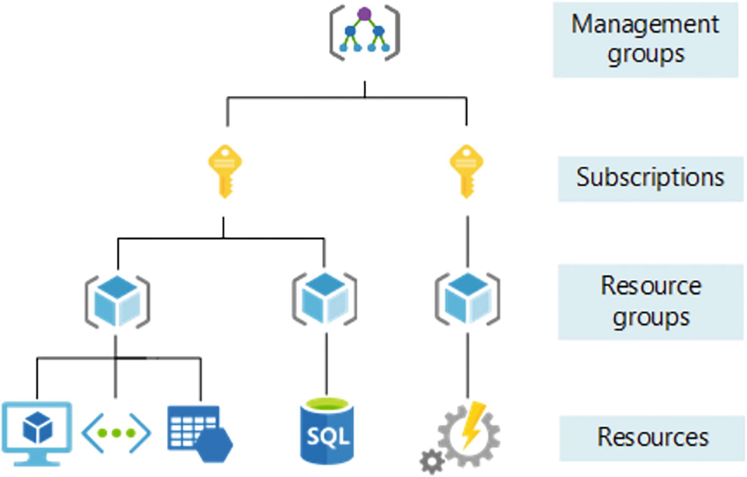
A model diagram represents the management groups, subscriptions, resource groups, and resources of azure subscription segmenting subnets.
Azure subscriptions
Virtual Network : Azure Virtual Network is a fundamental building block that creates a private network within the Azure environment. With VNET, you can enable many types of resources, such as Azure Virtual Machines, to securely communicate between the on-premises resources and any Internet resources. See Figure 3-14.

A model diagram represents the on premises network, encrypted tunnel, internet, direct connection to subnet 1 is traffic filtering, and subnet 2 is other azure services pf virtual network.
Azure Virtual Network
Network Security Group(NSG): With NSGs , you can control traffic between resources within and outside the virtual network. You can also maintain granular access control by creating a separate logical environment for subnets, VMs, or group of VMs. See Figure 3-15.

A model diagram represents the internet, H T T P, virtual network, and subnet 1 contains V M 1, 2, N I C 1, N S G 1,2, subnet 2 contains V M 3, N I C 1, N S G 2 and subnet 3 contains V M 4.
Network security group
Application Security Group (ASG) : Application Security Groups are the same as Network Security Groups, but they are referenced with respect to the application context. This allows groups of VMs under the application tag and defines the rules for each underlying VM. See Figure 3-16.

The two model diagrams represent the web servers and database servers, and the table represents the name, source, and destination in columns of the application security group.
Application security group
Azure Firewall : Azure has a cloud-native firewall that can be deployed to a virtual network or an Azure virtual WAN. It filters the traffic between the cloud resources, the Internet, and the on-premises server/resources. With Azure Firewall, you can create rules and policies and specify allow/deny traffic rules using layer 3 to layer 7 controls. You can also filter the traffic. See Figure 3-17.

A model diagram represents the attacker, phishing email, azure firewall, host metadata, and encryption keys of the azure firewall.
Azure Firewall
Single VNET: With a single VNET , all the application components reside in a single virtual network. When you are working in a single region and VNET can’t span across multiple regions, you can use the single VNET approach. See Figure 3-18.

A block diagram represents the azure region, which contains a virtual network of subnet 1 is database servers in S Q L, and subnet 2 is web servers of single V N E T.
Single VNET
Common ways to segment subnets or application groups include using the Network Security Groups and Application Security Groups . In Figure 3-18, Subnet 1 uses a SQL database and Subnet 2 uses Azure VMs. You can configure NSG to allow the communication between Subnet 1 and Subnet 2.
Multiple VNET with VNET peering : Using the multiple VNET approach, you can spread resources across multiple VNETs. You can enable communication across the VNETs using VNET peering. VNET peering is recommended when you need to group applications in separate VNETs. When you use VNET peering, connecting between VNETs is not transitive. See Figure 3-19.

A block diagram represents the azure region 1 and 2 and virtual networks 1, 2, and 3 of a multiple V N E T with peering.
Multiple VNETs with peering
Controlling Routing Behavior
When you set up a virtual network for an application, you can determine the traffic between the services and within the virtual network by controlling the routing behavior. When you create a virtual network, you have default routes that will be enabled to allow that communication. In many cases, these default routes are sufficient to control the traffic within the VNET. If customization is required, you can customize the networking routes
System routes : Azure automatically creates a system route and assigns the routes to each subnet within a virtual network. Since these system routes are created by default, you can’t create them and you don’t have permission to remove them. But you can change or override the existing system routes using the custom routes. Azure creates default system routes for each subnet and it adds optional default routes to specific subnets using the Azure capabilities.
Default routes : Each default route contains an address prefix and the next hop type. Whenever a virtual network is created, Azure automatically creates the default system routes listed in Table 3-1.
Default Routing Rules
-  A table represents the default routing rules, which contain source, address prefixes, and next hop type in columns, and the source column represents default. A table represents the default routing rules, which contain source, address prefixes, and next hop type in columns, and the source column represents default.
|
Apart from the default routes, there are various other optional routes that can be configured. Depending on the capability, Azure adds optional default routes to specific subnets or to all subnets in the virtual network. See Table 3-2.
Optional Default Routes
-  A table represents the optional default routes, which contain source and address prefixes in columns, and source contains the default, virtual network gateway. A table represents the optional default routes, which contain source and address prefixes in columns, and source contains the default, virtual network gateway.
|
Custom routes : You can create custom routes either by creating user-defined routes or by exchanging the Border Gateway Protocol (BGP) between the on-premises network gateway and the Azure network gateway.
User-defined routes : You can create user-defined routes in Azure to override Azure’s default system routes or add more routes to the subnet’s route table. You can create a route table and an associate route table to zero or more virtual network subnets.
Border Gateway Protocol (BGP) : On-premises network gateway can exchange routes with the cloud Azure network gateway using the Border Gateway Protocol. Using BGP with an Azure virtual network depends on the type of gateway. When you exchange routes with Azure using BGP, a separate route is added to the route table of all the subnets in the virtual network. See Figure 3-20.

A model diagram represents the border gateway protocol, which contains R R, P E 3, P E 1, P 2, P E 2, P 1, P E 4, and P E 5 with prefix 172.16.2.0 by 24.
Border Gateway Protocol
VPN Gateway route propagation can be disabled on a subnet using the route table. Connectivity with VPN connection is achieved using the custom routes with the Virtual Network Gateway.
Using Gateways and Firewalls
In order to secure your Azure application workload, you have to make sure that all security measures—including authentication, authorization, and encryption—are properly in place. You can add security layers to the virtual machine where the application is hosted and deployed. These layers protect inbound flow from the users.
Azure Firewall is a next-generation firewall that provides network address translation. It is an intelligent firewall security and it provides the best of threat protection for the workload running in the cloud.
Azure Firewall standard provides L3-L7 filtering and threat intelligence directly from Microsoft Cyber Security . Azure Firewall Premium has advanced capabilities compared to Azure Firewall. These advanced capabilities include byte sequence in network traffic or attacks done by the antivirus or malware software.
Reliability
Security
Cost optimization
Operational excellence
Performance excellence
Azure Application Gateway is a load balancer that helps you control and manage the traffic of web applications. With the application gateway, you can make routing decisions based on the HTTP requests.
With Azure Application Gateway , you can perform URL-based routing. You can enable Secure Socket Layer (SSL) /Transport Layer Security (TLS) gateways, auto-scaling, zone redundancy, static VIPs, and web application firewalls by enabling the application gateway.
Conclusion
This chapter explored in detail the software-defined networks and the approach to be followed by an enterprise organization . You also learned about various network topologies and how to use subnets in the virtual network to isolate the network traffic. You also learned that you can control and route traffic using the NSG rules and ASG.