
11
Working with NeoPixels and a MAX7219 Display
In the previous chapter, we learned how to work with a built-in accelerometer and compass. We explored these onboard devices with MicroPython programming.
This chapter will explore how to interface NeoPixels and their compatible devices with the Micro:bit. We will also explore a MAX7219 driver-based display. We will learn how to program them and also create breathtaking projects with them. We will explore the following list of topics together:
- NeoPixel products
- The NeoPixel library
- Adding interactivity to the projects
- Interfacing a MAX7219/7221-based 7-segment 8-digit display
Let’s get started with NeoPixel and MAX 7219 display programming.
Technical requirements
For this chapter, we will need any one of the following hardware products:
- NeoPixel or compatible strip or string
- NeoPixel or compatible ring
- NeoMatrix or compatible matrix
- MAX7219 7-segment 8-digit display
NeoPixel products
NeoPixels are a brand of a range of related products manufactured by Adafruit (https://www.adafruit.com/category/168). They are based on individual LEDs (WS2812, WS2811, and SK6812). These LEDs are Red, Green, and Blue (RGB) or Red, Green, Blue, and White (RGBW)-colored LEDs. They use the Single Wire Protocol for communication. Let’s understand what it is. As you may recall, in Chapter 6, Interfacing External LEDs, we interfaced the Micro:bit board with RGB LEDs with four pins (one for each color and one for a common anode or common cathode). This circuit configuration can only support a limited number of RGB LEDs with the Micro:bit (or any board/device for that matter) as it has a limited number of GPIO pins that can be used for digital I/O. So, the drawbacks of this configuration are as follows:
- Utilization of too many pins
- Cannot support more RGB LEDs
- Must write separate code blocks to handle each LED
NeoPixel only uses one GPIO pin for many RGB LEDs. Yes! You read that correctly. It requires a single digital I/O pin of the board it is interfaced to. Depending on the configuration, a NeoPixel product can have any number of LEDs; we will have a look at several variations in this chapter, and learn how to build circuits and how to program them.
You can check online marketplaces or the product page of Adafruit (https://www.adafruit.com/category/168) to procure NeoPixel products. Alternatively, many manufacturers manufacture WS2812, WS2811, and SK6812-based products and sell them under their own brands. While purchasing, make sure that the product is NeoPixel-compatible.
The following figure shows a WS2812-based individual NeoPixel:
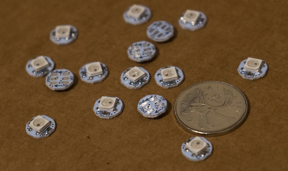
Figure 11.1 – Individual NeoPixel boards (courtesy: https://commons.wikimedia.org/wiki/File:Mini_NeoPixel.jpg)
The following figure shows WS2812-based LEDs glowing in different colors. This should give you a fair idea of this hardware component’s color spectrum and luminary capabilities:
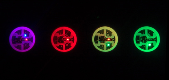
Figure 11.2 – NeoPixel LEDs glowing in different colors (courtesy: https://commons.wikimedia.org/wiki/File:WS2812Closeup2.jpg)
Let’s discuss what pins the NeoPixel products typically have:
- + or DC pin: This could be labeled as +5 DC, 4-7 DC, or VDD on various products. We connect it to an external power supply of compatible output. The Micro:bit board may not be able to power the NeoPixel device if it has got too many LEDs. Some NeoPixel devices have more than one pin labeled +. One is for input voltage, while the other acts as power output if we plan to attach multiple NeoPixels in series. However, when using the series configuration, I prefer to power every NeoPixel product directly from the breadboard’s power supply.
- GND: This one is to be connected to the common ground. If there is a pair of them in your NeoPixel product, the other GND pin should be connected to the GND pin of the Micro:bit. This provides the common ground for all the devices as all the GND pins of any NeoPixel or compatible product are connected internally.
- DIN: This pin is the data input for the Single Wire Protocol. It is connected to one of the digital GPIO pins of the Micro:bit. Throughout this chapter, I will be using pin 0 for the demonstrations. However, you can use any pin.
- DOUT: This is the data output pin, which is to be connected to the DIN pin of the next NeoPixel product if we are connecting multiple NeoPixels in a series. Many NeoPixel-compatible products do not have this, and cannot be used for series configuration.
Now, let’s have a look at the various NeoPixel form factor products one by one. I am using the Fritzing parts downloaded from the following URLs:
- https://forum.fritzing.org/t/ws2812-rgb-led-strip-matrix/6339
- https://github.com/adafruit/Fritzing-Library
- https://github.com/vemeT5ak/fritzing-and-eagle/blob/master/SMD%20RGB%20LED%20(WS2812B).fzpz
We have already seen figures of individual NeoPixel boards with a single LED. We can string them together in a serial chain, as follows:
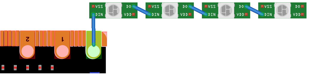
Figure 11.3 – WS2821-based individual NeoPixel boards connected in a series
Connect all the VDD pins to the external +5 V power supply and the VSS pins to the common ground. This will complete the circuit. So long as we provide enough external power, a reasonable number of NeoPixels can be attached without any issue.
We also have NeoPixels in the form of sticks, as follows:
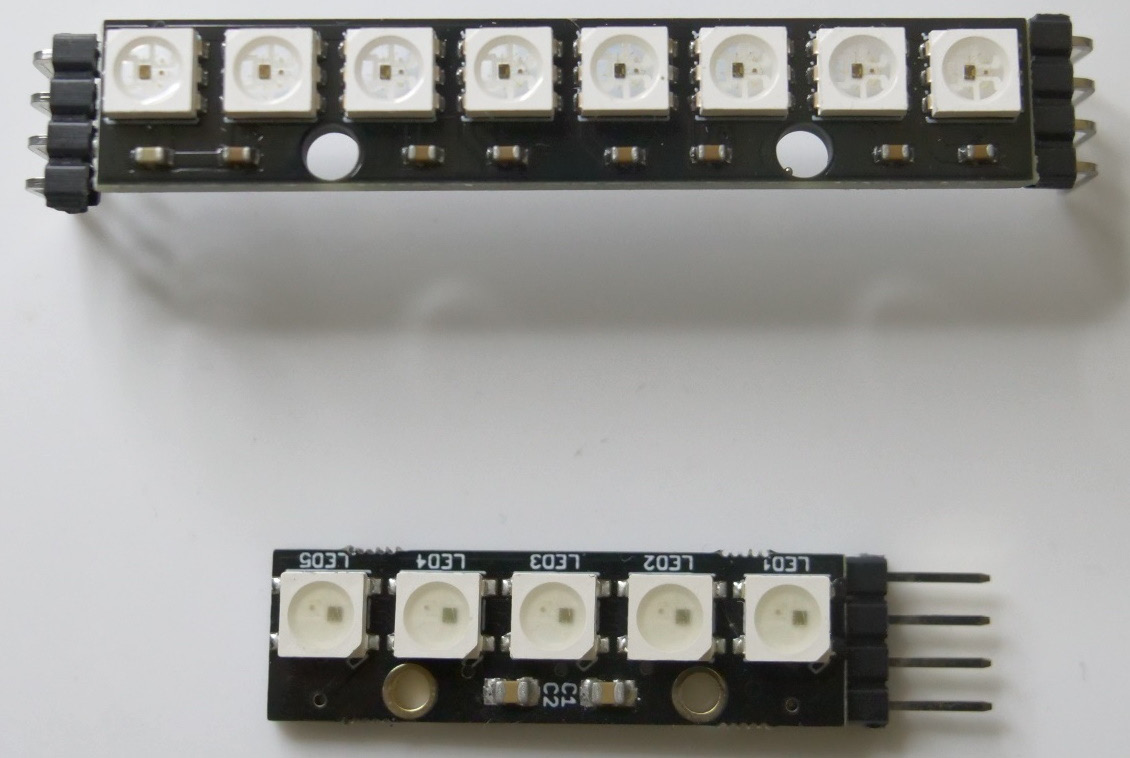
Figure 11.4 – NeoPixel sticks
We can see the pin labeling on the rear, as follows:
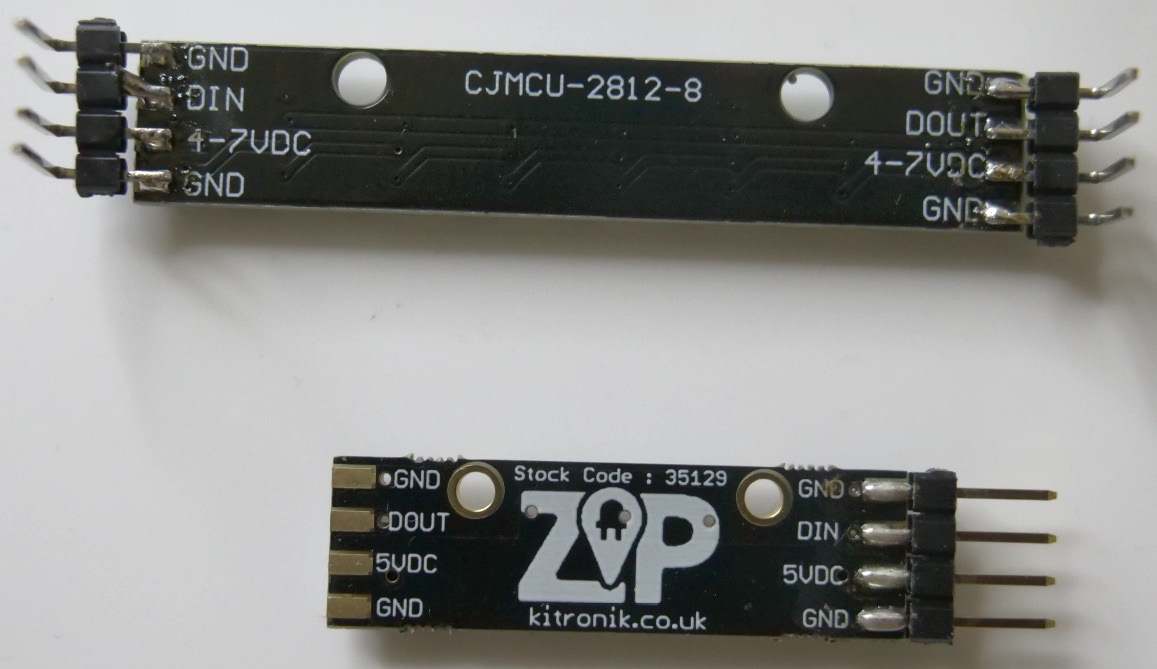
Figure 11.5 – NeoPixel sticks – pin description
Both these products have two sets of ground pins. Connect the +DC pin to the power supply for adequate output. One ground pin is to be connected to the Micro:bit’s GND pin, while another ground pin is to be connected to the common ground. We can connect the DIN pin to pin 0 of the Micro:bit as follows:
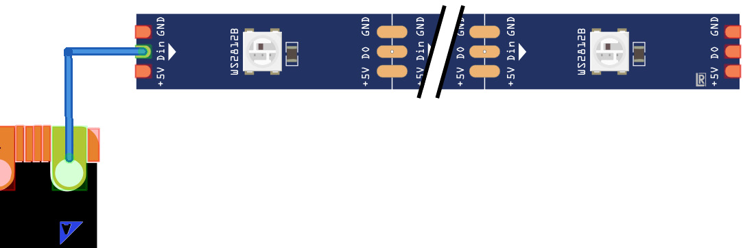
Figure 11.6 – NeoPixel stick/strip used in a circuit
Another popular product is the NeoPixel ring. The following figure shows the front of a ring with 16 LEDs:
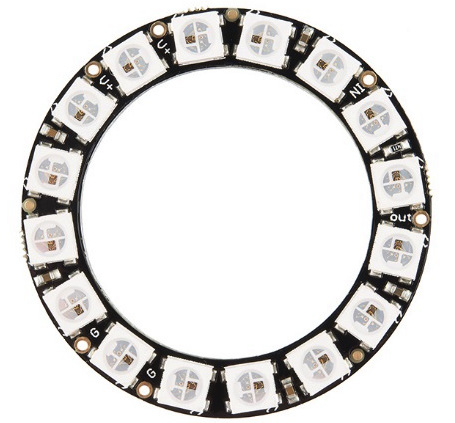
Figure 11.7 – The front of a 16-LED NeoPixel ring (courtesy: https://commons.wikimedia.org/wiki/File:12664-02a.jpg)
The rear of this ring has pins, as shown here:
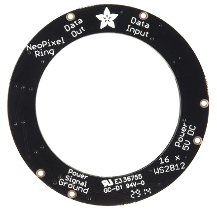
Figure 11.8 – The rear of a 16-LED NeoPixel ring (courtesy: https://commons.wikimedia.org/wiki/File:12664-03a.jpg)
We can even have bigger rings, as shown here:
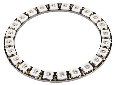
Figure 11.9 – A 24-LED ring (courtesy: https://commons.wikimedia.org/wiki/File:12664-03a.jpg)
We can create a circuit as follows:
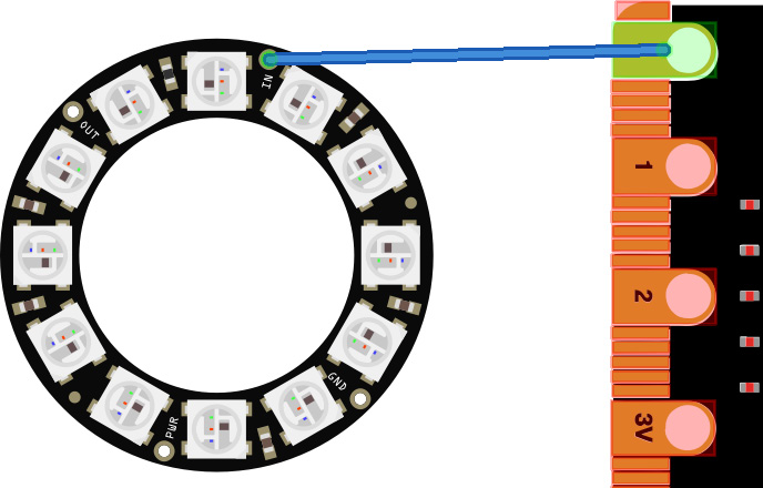
Figure 11.10 – A 12-LED ring connected to pin 0 of the Micro:bit
Do not forget to connect the PWR pin of the ring to +5V and the GND pin to a common ground. There are other form factors too. You can check them out at https://learn.adafruit.com/adafruit-neopixel-uberguide/form-factors.
We will be using this circuit for demonstration purposes; however, you can use any product.
In the next section, we will learn how to create interesting projects with the NeoPixel library.
The NeoPixel library
The NeoPixel library in the Micro:bit allows us to write programs for NeoPixel products and their compatible devices. You can find out more about the library at https://microbit-micropython.readthedocs.io/en/v1.0.1/neopixel.html. The library comes with MicroPython; we do not have to do anything extra to enable it. Let’s start coding. I am going to connect the NeoPixel 12-LED ring to pin 0 for this chapter. The code examples have been written while considering this circuit. However, I will explain where to make changes if you have opted for a different configuration.
Check the following code example:
from microbit import *
from neopixel import NeoPixel
num_pixels = 12
ring = NeoPixel(pin0, num_pixels)
for i in range(0, 120, 10):
    print(i)
    ring[int(i/10)] = [0, 0, i]
ring.show()
The first two lines are used to import the required libraries. Then, we assign the number of LEDs in the NeoPixel product to the num_pixels variable in the program. Then, we create a ring object for the NeoPixel product. We pass the pin number and the number of pixels as arguments to the constructor NeoPixel(). It is not mandatory to name the object ring in the program. It is just a variable name, and I usually name them to reflect real-life objects. If I were using a NeoPixel stick, then I would name it stick. Once the ring/stick object has been created, we can treat it as a list. If there are n pixels in the NeoPixel product, then the index of the list will start at 0 and end at n-1. We can assign a list representing the intensities of red, green, and blue to every member of the ring object. I have used a for loop for this. We can use various combinations of colors to achieve different effects. In the end, we can call the show() method to push all these values to the NeoPixel product. In this example, we will assign values ranging from 0 to 110 in increments of 10 to all 12 pixels (0, 10, 20… up to 110). This will create a static fading effect. We can modify the contents of the for loop as follows to create the blending effect:
for i in range(0, 120, 10):
    print(i)
    ring[int(i/10)] = [120-i, 0, i]
The print() call in the loops is only for debugging; you can comment it out if you wish.
We can create a rotating pattern with the following program:
from microbit import *
from neopixel import NeoPixel
num_pixels = 12
ring = NeoPixel(pin0, num_pixels)
shift = 0
values = [0, 10, 20, 30, 40, 50, 60, 70, 80, 90, 100, 110]
try:
    while True:
        for i in range(0, num_pixels, 1):
            curr_value = values[int((i + shift) % num_pixels)]
            ring[i] = [0, 110-curr_value, curr_value ]
        ring.show()
        sleep(1000)
        shift = shift + 1
except KeyboardInterrupt as e:
    print("Interrupted by the user...")
In the preceding program, we are defining a list known as values. We have written an infinite loop to assign the values of this list to the LEDs in the NeoPixel product in a rolling window fashion. In the infinite loop, we shift the window by one position in the list with the shift = shift + 1 statement. We can change the speed of the effect by modifying the argument that’s passed to the sleep() call. We can see the printed values of the rolling window in the REPL shell.
By changing the values list, we can implement a lot of effects, as follows:
from microbit import *
from neopixel import NeoPixel
num_pixels = 12
ring = NeoPixel(pin0, num_pixels)
shift = 0
values = [[0, 0, 0], [0, 0, 120], [0, 120, 0], [120, 0, 0],
          [120, 120, 120], [120, 120, 0], [120, 0, 120], [0, 120, 120],
          [0, 0, 0], [0, 0, 40], [0, 40, 0], [40, 0, 0]]
try:
    while True:
        for i in range(0, num_pixels, 1):
            print(values[int((i + shift) % num_pixels)])
            ring[i] = values[int((i + shift) % num_pixels)]
        print('--')
        ring.show()
        sleep(1000)
        shift = shift + 1
except KeyboardInterrupt as e:
    print("Interrupted by the user...")
Run the preceding program to see the output. We will see another effect with the following list:
values = [[0, 0, 0], [0, 63, 0],
          [0, 0, 0], [63, 0, 0],
          [0, 0, 0], [0, 0, 63],
          [0, 0, 0], [0, 63, 0],
          [0, 0, 0], [63, 0, 0],
          [0, 0, 0], [0, 0, 63]]
We can create a chaser effect as follows:
from microbit import *
from neopixel import NeoPixel
num_pixels = 12
ring = NeoPixel(pin0, num_pixels)
try:
    while True:
        for i in range(0, num_pixels):
            ring[i] = [0, 0, 100]
            ring[i-1] = [0, 100, 0]
            ring[i-2] = [100, 0, 0]
            ring.show()
            sleep(50)
            ring.clear()
except KeyboardInterrupt as e:
    print("Interrupted by the user...")
The clear() method clears all the pixels when called. In this example, we have assigned different intensities of red, green, and blue to consecutive pixels to create a chaser effect. In each iteration, we change the index of those pixels. So, at any given moment, only three LEDs will be on and the rest of the LEDs in the ring will be off.
We can create a chaser effect with a single LED blinking with a random color by modifying the loop in the preceding code like so:
try:
    while True:
        for i in range(0, len(ring)):
            red = randint(0, 60)
            green = randint(0, 60)
            blue = randint(0, 60)
            ring[i-1] = [0, 0, 0]
            ring[i] = [red, green, blue]
            ring.show()
            sleep(100)
except KeyboardInterrupt as e:
    print("Interrupted by the user...")
In this example, we are randomizing the color of a single LED in every iteration of the loop.
We can also create beautiful LED patterns of red, green, and blue that glow in an infinite loop, as follows:
from microbit import *
from neopixel import NeoPixel
num_pixels = 12
ring = NeoPixel(pin0, num_pixels)
red = [31, 0, 0]
green = [0, 31, 0]
blue = [0, 0, 31]
delay = 500
def glowAll(col):
    for i in range(0, len(ring)):
        ring[i] = col
    ring.show()
    return 0
try:
    while True:
        glowAll(red)
        sleep(500)
        glowAll(green)
        sleep(500)
        glowAll(blue)
        sleep(500)
except KeyboardInterrupt as e:
    print("Interrupted by the user...")
The user-defined glowAll() function assigns the passed color to every LED in the NeoPixel product.
We can assign a random color to each pixel in each iteration, as follows:
from microbit import *
from random import randint
from neopixel import NeoPixel
num_pixels = 12
ring = NeoPixel(pin0, num_pixels)
delay = 500
def glowAll():
    for i in range(0, len(ring)):
        ring[i] = [randint(0, 255),
                   randint(0, 255),
                   randint(0, 255)]
    ring.show()
    return 0
try:
    while True:
        glowAll()
        sleep(500)
except KeyboardInterrupt as e:
    print("Interrupted by the user...")
To assign the same color to all the LEDs randomly, we have to modify the user-defined function, as follows:
def glowAll():
    red = randint(0, 255)
    green = randint(0, 255)
    blue = randint(0, 255)
    for i in range(0, len(ring)):
        ring[i] = [red, green, blue]
    ring.show()
    return 0
Try this modification and run the code to see the output. Do not forget to save the file with a different filename.
We can also create a beautiful fading effect with the following code:
from microbit import *
from neopixel import NeoPixel
num_pixels = 12
ring = NeoPixel(pin0, num_pixels)
delay = 1
step = 1
def glowAll(col):
    for i in range(0, len(ring)):
        ring[i] = col
    ring.show()
    return 0
try:
    while True:
        for i in range(0, 255, step):
            glowAll((i, 0, 0))
            sleep(delay)
        for i in range(255, 0, -step):
            glowAll((i, 0, 0))
            sleep(delay)
        for i in range(0, 255, step):
            glowAll((0, i, 0))
            sleep(delay)
        for i in range(255, 0, -step):
            glowAll((0, i, 0))
            sleep(delay)
        for i in range(0, 255, step):
            glowAll((0, 0, i))
            sleep(delay)
        for i in range(255, 0, -step):
            glowAll((0, 0, i))
            sleep(delay)
except KeyboardInterrupt as e:
    print("Interrupted by the user...")
We can adjust the delay and step variables to modify the fade’s duration.
The MicroPython reference (https://docs.micropython.org/en/latest/esp8266/tutorial/neopixel.html) contains a code example for ESP8266 boards. It won’t run on a Micro:bit device as is, so I modified it and made it run on the Micro:bit. The following code has been adapted for the Micro:bit. Let’s import the libraries and initialize the variables:
from microbit import *
from neopixel import NeoPixel
num_pixels = 12
ring = NeoPixel(pin0, num_pixels)
Now, let’s define the demo function:
def demo(ring, num_pixels):
    n = num_pixels
The following code block creates the cycle effect:
    # cycle
    for i in range(4 * n):
        for j in range(n):
            ring[j] = [0, 0, 0]
        ring[i % n] = [255, 255, 255]
        ring.show()
        sleep(25)
The following code creates the bounce effect:
    # bounce
    for i in range(4 * n):
        for j in range(n):
            ring[j] = [0, 0, 128]
        if (i // n) % 2 == 0:
            ring[i % n] = [0, 0, 0]
        else:
            ring[n - 1 - (i % n)] = [0, 0, 0]
        ring.show()
        sleep(60)
The following code creates the fade effect:
    # fade in/out
    for i in range(0, 4 * 256, 8):
        for j in range(n):
            if (i // 256) % 2 == 0:
                val = i & 0xff
            else:
                val = 255 - (i & 0xff)
            ring[j] = [val, 0, 0]
        ring.show()
    ring.clear()
Now, let’s write the code that will call the function we just wrote:
try:
    while True:
        demo(ring, num_pixels)
except KeyboardInterrupt as e:
    print("Interrupted by the user...")
Since we are writing a separate function and passing it to the object of the NeoPixel product, extending this code for multiple NeoPixels connected to separate pins is easy. This program combines all the demonstrations we have seen earlier into a single program. You will find plenty of examples of NeoPixels for other boards. You can use the logic and the code provided here and then adapt it for your Micro:bit, as I did in this example, to hone your programming skills further.
We can also make a single LED glow in a random color in each iteration, as follows:
from microbit import *
from neopixel import NeoPixel
import random
num_pixels = 12
ring = NeoPixel(pin0, num_pixels)
try:
    while True:
        ring[(random.randint(0, num_pixels-1))] =   [(random. randint(0, 32)),
    (random. randint(0, 32)),
    (random.randint(0, 32))]
        ring.show()
        sleep(200)
        ring.clear()
except KeyboardInterrupt as e:
    print("Interrupted by the user...")
We can combine all the knowledge we have gained to create a rainbow effect, as follows:
from microbit import *
from neopixel import NeoPixel
num_pixels = 12
ring = NeoPixel(pin0, num_pixels)
def rainbow(np, num, offset, bright=1):
    rb = [(127, 0, 0), (127, 63, 0), (127, 127, 0), (0, 127, 0),
          (0, 127, 127), (0, 0, 127), (63, 0, 127), (127, 0, 0)]
    for i in range(num):
        t = 7*i/num
        t0 = int(t)
        r = round((rb[t0][0] + (t-t0)*(rb[t0+1][0]-rb[t0][0]))*bright) >> 2
        g = round((rb[t0][1] + (t-t0)*(rb[t0+1][1]-rb[t0][1]))*bright) >> 2
        b = round((rb[t0][2] + (t-t0)*(rb[t0+1][2]-rb[t0][2]))*bright) >> 2
        ring[(i+offset)%num] = [r, g, b]
n = 0
try:
    while True:
        rainbow(ring, num_pixels, offset = n)
        ring.show()
        n = n + 1
        sleep(200)
except KeyboardInterrupt as e:
    print("Interrupted by the user...")
In this example, we are defining a custom function called rainbow() that accepts the NeoPixel object, the number of pixels, the offset (we will explain this soon), and the brightness as arguments. Since this is a modular function, we can call it multiple times for different NeoPixels by changing the arguments. We have a predefined list of color values, rb, which is used to generate the rainbow colors. Based on the number of pixels passed to the function call, it computes the shades of the rainbow. We can control the brightness by passing the desired value as an argument. We are using the left-shift operator (>>) to shift the computed values of red, green, and blue toward the right by effectively reducing their brightness. The >>2 operation shifts a value to the right and reduces its magnitude. If you feel that the colors are too bright, you can change them to >>3 and >>4. The offset variable increments in every iteration and is passed to the function call. We use it to shift the value of the rainbow by one position every time. It creates the rotation effect. Run the code and see it in action. If you wish to see the changing values of color, you can print them with print().
This is how we can create great projects with NeoPixel components and Micro:bit. There is a lot of room to add your own creative ideas to these projects. As an exercise, create new lighting patterns with the same setup.
Adding interactivity to the projects
We can use the built-in push buttons A and B of the Micro:bit to control the speed of the rainbow. We have to use the if statement in the while loop. We need to have an extra variable for the speed as follows:
num_pixels = 12
ring = NeoPixel(pin0, num_pixels)
maxdelay = 400
mindelay = 10
delay = int(maxdelay+mindelay)/2
And we have to make the following modification to the loop:
try:
    while True:
        rainbow(ring, num_pixels, offset = n)
        ring.show()
        n = n + 1
        if (button_a.is_pressed() and (delay < maxdelay)):
            delay = delay + 10
        elif (button_b.is_pressed() and (delay > mindelay)):
            delay = delay - 10
        else:
            pass
        print(delay)
        sleep(delay)
except KeyboardInterrupt as e:
    print("Interrupted by the user...")
Now, run the program and control the speed of the rotation of the rainbow with the built-in buttons. You can also add additional logic in the else block if you wish.
Interfacing a MAX7219/7221-based 7-segment 8-digit display
MAX7219/7221 are 7-segment 8-digit driver ICs that use the serial interface. We can find their documentation at the following web pages:
- https://www.maximintegrated.com/en/products/power/display-power-control/MAX7219.html
- https://datasheets.maximintegrated.com/en/ds/MAX7219-MAX7221.pdf
Following is the photograph of a MAX7219-based 7-segment 8-digit LED display:
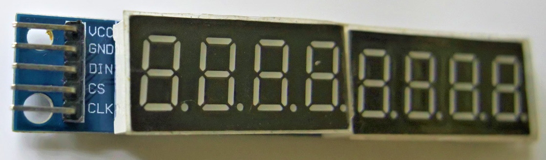
Figure 11.11 – 7-segment 8-digit display with pins
We can see all the pins clearly in Figure 11.11. Connect VCC to the 3V pin of the Micro:bit and GND to the ground. Connect DIN and CLK to pins 15 and 13 of the Micro:bit, respectively. Finally, connect CS to pin 0. We can use any digital I/O pin of the Micro:bit. I have written the demonstration programs assuming that pin 0 is connected to CS. If you decide to change the pin, please make the appropriate changes to the program.
I have referred to the library at https://github.com/microbit-playground/matrix7seg to interface the display with the Micro:bit. Download the file at https://github.com/microbit-playground/matrix7seg/blob/master/matrix7seg.py to your local computer. Now, open that file with the Thonny editor. To do so, in the main menu, go to View | Files:

Figure 11.12 – Files view of Thonny
Make sure that you are not running any program in the REPL shell when you open this view; otherwise, the Micro:bit files will not be visible. In Figure 11.12, we can see that the Micro:bit has a main.py file. Now, save the current file (matrix7seg.py) to the Micro:bit. After we save the file to the Micro:bit, the Micro:bit file list will change, as follows:

Figure 11.13 – Files on the Micro:bit
This is how we can install a custom MicroPython library to any device running MicroPython. We can use the functionality from this library with the import statement. Save the following program to the Micro:bit as main.py:
from matrix7seg import Matrix7seg
from microbit import spi, pin0, sleep
seg_display = Matrix7seg(spi, pin0)
seg_display.write_number(1234)
seg_display.show()
sleep(2000)
seg_display.write_number(1234, zeroPad=True)
seg_display.show()
sleep(2000)
seg_display.write_number(12345678)
seg_display.show()
sleep(2000)
seg_display.write_number(1234, leftJustify=True)
seg_display.show()
sleep(2000)
In the first two statements, we have imported all the needed modules. The seg_display = Matrix7seg(spi, pin0) statement creates an object for the display. The write_number() method is self-explanatory. We can pad the number with preceding zeros to fill the display and left-justify the text with the arguments. All the possible usages are shown in this example.
Let’s create a simple counter, as follows:
from matrix7seg import Matrix7seg
from microbit import spi, pin0, sleep
seg_display = Matrix7seg(spi, pin0)
i = 0
try:
    while True:
        seg_display.write_number(i)
        seg_display.show()
        sleep(1000)
        i = i + 1
        if i > 9:
            i = 0
except exception:
    print("Interrupted by user...")
Here, we are displaying the value of an integer variable and incrementing it. When the value reaches 10, we reset it to 0. We can extend this program and add interactivity with the built-in push buttons. As an exercise, create a stopwatch using the display and the built-in push buttons. One push button should reset the stopwatch, while the other should stop it. You just need to modify the preceding example.
This is how we can use an external library in our code example for the Micro:bit.
Summary
This chapter explored the various NeoPixel products and the MAX7219-based 7-segment 8-digit display. We programmed them with the NeoPixel product and a custom library, respectively. As an exercise, try combining these LED-based displays with the built-in or external push buttons so that you have interactivity in your projects.
The code bundle for this chapter contains a few additional programs. As an exercise, go through those programs and understand their logic.
The next chapter will explore programming the Micro:bit to produce music and speech. We will learn how to connect an external speaker to the Micro:bit. We will also learn how to use a built-in microphone and speaker in the Micro:bit V2.
Further reading
The content available at the following URLs will enhance your understanding of NeoPixels further:
- https://learn.adafruit.com/micro-bit-lesson-3-neopixels-with-micro-bit
- https://docs.micropython.org/en/latest/esp8266/tutorial/neopixel.html
- https://microbit-micropython.readthedocs.io/en/v1.0.1/neopixel.html
- https://www.adafruit.com/category/168
If you plan to use any of the examples provided in the online tutorials, make sure that it is written for the Micro:bit, not any other board. If it is written for another board, then modify it appropriately.