
14
Advanced Features of the Micro:bit
We have explored a variety of applications of using the Micro:bit throughout this book. However, we have not explored the complete set of features available on the Micro:bit board. A variety of sensors are built into the board that can be used to perform interesting operations. In other microcontrollers, all such sensors are not inbuilt, so we must attach them separately. External sensor integration consumes a greater number of pins as well as power. Therefore, the Micro:bit has a huge advantage over other similar boards.
In this chapter, we will learn about the sensors built into the Micro:bit. Some of these features are present in both versions, while a few are only present in V2. We will learn how to access each sensor and control some output devices connected at different pins. We can also display useful information from these sensors on the LED matrix. We will discuss the following sensors of the Micro:bit:
- Capacitive touch
- Temperature sensor
- Light sensor
Let us get started by looking at the features of the Micro:bit with MicroPython.
Technical requirements
Apart from the usual setup, the demonstrations in this chapter need the following components:
- External batteries
- A torch for providing artificial light
- A flame or heat source for temperature control
Capacitive touch
Touch is one of our basic senses. We touch various objects with our fingers to feel them and obtain information about their texture, temperature, and other surface properties. On the Micro:bit, round pins 0, 1, and 2 can be touched to provide input from the human touch. These pins are available on both versions of the Micro:bit. They work on the principle of resistive touch. When we touch these pins, a connection to the ground of the Earth is established through our fingers. Therefore, the ground is always required while providing inputs from these pins.
In this chapter, we will learn about the touch sensor, which is only supported on V2. The sensor is present on the front side of the Micro:bit. Its location is above the LED matrix, as shown in Figure 14.1:

Figure 14.1 – Capacitive touch sensor on the Micro:bit V2
Any capacitive surface activates the capacitive touch sensor. Our skin is a capacitive surface as we access modern smartphones through the same capacitive touch technology. Capacitive touch does not require a ground connection. Let us make a very simple application using the Micro:bit capacitive touch sensor. We will display the heart image if we touch the sensor and a blank display if we remove our finger from the sensor. We will use the pin_logo module to detect and access the capacitive touch on the Micro:bit V2.
In this code, initially, we must explicitly declare that pin_logo will accept capacitive touch by using the following command:
pin_logo.set_touch_mode(pin_logo.CAPACITIVE)
Then, the code is a simple conditional statement that is triggered by the detection of touch on pin_logo. If the touch is not detected, the display will turn blank:
from microbit import *
pin_logo.set_touch_mode(pin_logo.CAPACITIVE)
while True:
    if pin_logo.is_touched():
        display.show(Image.HEART)
    else:
        display.clear()
Now, let us make a slight modification to the code. We will set a timer to count the amount of time for which the touch logo was touched. We will declare a variable named set_timer to count the running time. When it is no longer being touched, the time will be displayed in seconds:
from microbit import *
pin_logo.set_touch_mode(pin_logo.CAPACITIVE)
set_timer = 0
while True:
    if pin_logo.is_touched():
        display.show(Image.HEART)
        sleep(50)
        set_timer = running_time()
    else:
        if set_timer > 0:
            time = running_time() - set_timer
            set_timer = 0
            display.clear()
            sleep(200)
            display.scroll(time / 1000)
In this section, we talked about the capacitive touch on the Micro:bit V2. This logo can be activated by the touch of human skin. This logo can be used to design any system that can be controlled by the touch response. We also designed a very simple application, where we displayed LED patterns upon touching the logo and displayed the amount of time for which the logo was touched.
Temperature sensor
A temperature sensor is a sensor that measures the temperature of any surface or its surroundings. It is an input device that provides information related to the temperature. We can find temperature sensors around us in a variety of appliances. For example, air conditioning works purely on the value of the surrounding temperature. The temperature sensors inside the appliance measure this temperature, and based on the temperature, the air conditioner’s compressor is turned on or off. The temperature sensor in industrial applications is also known as a thermostat. Most of the temperature sensors are integrated with a display to show the sensor’s output (measure temperature).
The BBC Micro:bit has a temperature sensor inbuilt inside the main processor. The main processor is located on the back of the Micro:bit. Figure 14.2 shows the processor’s location on a Micro:bit:
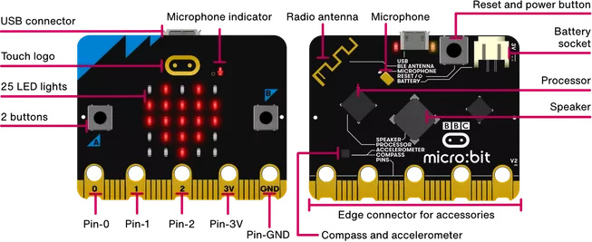
Figure 14.2 – Location of the main processor on a Micro:bit (courtesy: https://microbit.org/get-started/user-guide/overview/)
This sensor displays the internal temperature of the device in degrees Celsius. This temperature is also a good estimate of the temperature around the device. So long as the processor is not overloaded with heavy computational load, the temperature of the processor is almost the same as the surrounding temperature. So, we can program our Micro:bit so that it can sense the temperature, display that information on the LED matrix or any external display, and even trigger some actuators based on the temperature value.
Let us write some simple code to read the temperature value and display it on the LED matrix of the Micro:bit. We do not need any additional libraries to access the temperature sensor of the Micro:bit. In this code, we have declared a new variable named Temp:
from microbit import *
Temp = temperature()
while True:
    display.show('.')
    Temp = temperature()
    if button_a.was_pressed():
        display.scroll(Temp)
    sleep(1000)
    display.clear()
Now, let us make another application using the temperature sensor. We will continuously monitor the temperature and store it in the Temp variable. We will declare two new variables, namely MAX and MIN. These two variables have been created to store the minimum and maximum temperature observed during the whole monitoring time. We can take the Micro:bit to different places to observe these changes. Logically, we assign the value of the observed temperature (the Temp variable) to both variables at the beginning. Whenever the observed temperature is below the value of MIN, then we update the value of MIN to this newly observed value.
Similarly, if the value of the observed temperature is more than MAX at any time, then we must update the value of MAX to the newly observed value. We can display the maximum temperature by pressing button A and the minimum temperature by pressing B. The code for the system is as follows:
from microbit import *
Temp = temperature()
MAX = Temp
MIN = Temp
while True:
    display.show('.')
    Temp = temperature()
    if Temp < min:
        min = Temp
    if Temp > max:
        max = Temp
    if button_a.was_pressed():
        display.scroll(MAX)
    if button_b.was_pressed():
        display.scroll(MIN)
    sleep(1000)
    display.clear()
Figure 14.3 shows the possible simulations related to this system. In this case, the initial temperature was 25 degrees Celsius. We have varied the temperature between 12 to 35 degrees. Therefore, by pressing the related buttons, we can also display the minimum and maximum temperatures:

Figure 14.3 – Displaying the minimum and maximum temperature of the BBC Micro:bit
Now, we have a good idea about reading the temperature values from the Micro:bit. Let us integrate some actuators into the Micro:bit and control them with the temperature values. In this activity, we will design a simple temperature-controlled fan. If the temperature exceeds a certain threshold, we will turn on the fan to cool the surroundings. As the fan starts operating, the temperature will start coming down. And, if the temperature falls below the set threshold, the fan will be turned off. In the following code, we have set the threshold temperature at 27 degrees Celsius. The Micro:bit will display H if the temperature is more than 27 degrees and turn on the fan using analog pin 1. If the temperature is less than 27 degrees, then we will display L and turn off the fan:
from microbit import *
Temp = temperature()
while True:
    Temp = temperature()
    if Temp > 27:
        display.show("H")
        pin1.write_analog(255)
        sleep(1000)
    else:
        display.show("L")
        pin1.write_digital(0)
        sleep(1000)
    display.clear()
In this section, we discussed the temperature sensor present inside the Micro:bit. This sensor is present in both versions. In V2, it is located on the microprocessor. The temperature sensor provides the temperature in degrees Celsius. Using the MicroPython library, we can read the temperature and store it in a variable. We have designed simple applications using the temperature recorded from the Micro:bit, displaying different patterns based on the recorded temperature.
Light sensor
The Micro:bit V2 is a sensor-rich board. We know that there are 25 LEDs on the front to display anything using a combination of these LEDs. These 25 LEDs also have built-in light sensors to detect the intensity of light falling on them. The intensity of the light falling on these LEDs is read between 0 to 255. This means the highest intensity value will be read as 255, and the complete darkness will be read as 0. All the intensities in between are equally spaced in between these values.
Figure 14.4 shows the location of the light sensors on a Micro:bit:
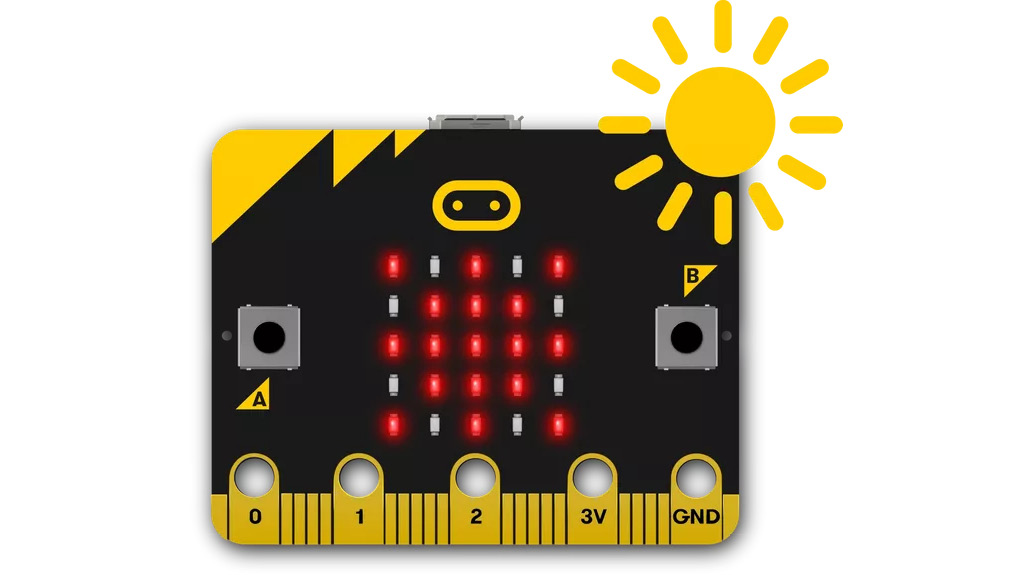
Figure 14.4 – Position of light sensors on a Micro:bit (courtesy: https://microbit.org/projects/make-it-code-it/sunlight-sensor/)
Important note
No fixed formula relates the intensity of light with the value. It will completely depend on our observations and adjustments for it to work properly with the light intensity values.
Let us write some simple code that will read the light level on the surface of the Micro:bit and display it on the Micro:bit. Since the number can be between 0 and 255, we can use the scroll function to display the value:
from microbit import *
while True:
    lightLevel = display.read_light_level()
    display.scroll(lightLevel)
    sleep(2000)
Now, we can read the value of the light intensity. Let us improve our design and develop a simple application using the same concept. In smart homes, there’s a very popular device called an automatic lighting system. The system detects the intensity of light in the surroundings, and if the intensity falls below a certain threshold, then the lights are switched on in that area. Such applications are popularly used for outdoor lights. For example, whenever the light intensity falls below a certain value in the evening, the outdoor lights will be switched on. And, as the light intensity increases, the lights will switch off automatically in the morning. This simple system saves a lot of electricity.
In this program, we will define a matrix using the Image function, where all the values are set to 8 to define the maximum output of the LEDs. Whenever light intensity is below a set threshold, all 25 LEDs are turned on. The intensity is decided based on the observed intensity values at the system’s location. Here, we have set the value to 100:
from microbit import *
while True:
    if display.read_light_level() < 100:
        display.show(Image(
        "88888:"
        "88888:"
        "88888:"
        "88888:"
        "88888"))
    else:
        display.clear()
    sleep(5000)
We can also attach any external lights via relays and switch them on using the same logic. Figure 14.5 shows an external LED connected to the Micro:bit. The external LED represents the streetlight (outdoor light) of the system:

Figure 14.5 – An external LED controlled by the intensity of surrounding lights
The program for the automated streetlight is simple and is shown here. We select a light intensity threshold value and set the digital pin 0 to high or low, depending on this value. The digital pin is set to HIGH for lower values; for higher values, it is set to LOW:
from microbit import *
while True:
    if display.read_light_level() < 100:
        display.show("L")
        pin1.write_digital(1)
        sleep(1000)
    else:
        display.show("H")
        pin1.write_digital(0)
        sleep(1000)
The light sensor can also be combined with the inbuilt speaker of the Micro:bit to develop a customized morning alarm. We will press button A at night to set the alarm. Whenever sunrise is detected (the indicator is that the light intensity goes high), the speaker can play a melody or even speak a customized message. In Chapter 12, Producing Music and Speech, we learned how to generate melodies and speech. We can combine these concepts to make a custom alarm for ourselves. The code for the alarm is as follows:
from microbit import *
import music
status = 0
while True:
    if (display.read_light_level()<100):
        display.show("N")
        sleep(100)
        if (button_a.is_pressed()):
            status = 1
            while status == 1:
                display.show("L")
                music.play(music.RINGTONE)
                if (button_b.is_pressed()):
                    display.show("Good Morning")
                    status = 0
                    sleep(1000)
The Micro:bit has an inbuilt light sensor on the front of the board. In this section, we discussed how to use the light sensor and read the light intensity falling on the board. Based on this light intensity, we designed a simple daylight alarm. This alarm can also be integrated with the onboard speaker and generate a musical tone when the alarm is triggered.
Summary
In this concise chapter, we explored a few additional unique features of the Micro:bit. First, we learned how to use the capacitive touch-enabled logo on the front of the Micro:bit. This capacitive touch logo does not require a ground connection. We also discussed the inbuilt temperature sensor. The sensor is inside the processor and gives a very good estimate of the surrounding temperature in degrees Celsius. We built applications using the observed temperature. In the end, we discussed the use of inbuilt light sensors. These sensors are present along with the LED matrix on the front of the Micro:bit. We developed an interesting alarm using this concept.
The next chapter will explore sewable components and wearable computing with the Micro:bit and MicroPython. We will also have a brief look at more software programming platforms that use the Micro:bit.