
Now you have a Tor bridge running and you can stop here. If you do, you'd be missing out on the ability to combine software with custom hardware on BBB. Our BBB Tor bridge currently has no visual feedback, so it's not obvious that it's working. Also, the only means to control the bridge is to log in to BBB over SSH and manipulate the configuration options. The Tor bridge is an appliance and it needs appliance controls. In this section, we'll add a front panel, which will give us an easy method to control the bridge's bandwidth and a quick indicator to know that the software hasn't crashed. In the following section, we'll add the software to interface with our bridge and control the hardware.
Note
If you decide to run a Tor relay, there are websites such as Tor atlas (https://atlas.torproject.org/) that will produce bandwidth graphs and display other information about your relay. Another tool that will also display information about your bridge is Globe (https://globe.torproject.org/).
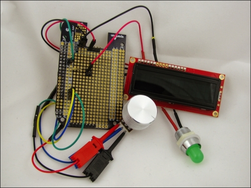
As this is our first project, we are going to use some basic components: a light-emitting diode (LED), a rotary potentiometer, and a liquid-crystal display (LCD), all shown in the following circuit diagram:
LCDs can been a bit tricky to work with, but SparkFun Electronics has combined a 16x2 LCD with a microcontroller so that it can use a serial interface instead of a more complicated parallel one. The serial interface is simpler because it only requires one data line to the device, whereas a parallel interface will require more wiring.
Our Tor bridge generates a lot of metadata, such as the bandwidth usage, the number of connections, and some Tor-specific statistics. For a home network, it's useful to know how much bandwidth your bridge is using, and it would be nice to know this without logging in to BBB all the time. In the serial LCDs, we will draw a graphical representation of the bandwidth usage. We'll use ten bars, each representing a tenth of the available bandwidth. If you see five bars, then the bridge is using half of the available bandwidth. The LCD selected for this project was LCD-09067 (SparkFun Electronics).
Note
SparkFun Electronics is an international distributor that ships products from Boulder, Colorado, in the United States. Some of the more common components recommended in this book can be replaced with equivalent ones in your local electronic store if you are trying to save on shipping. You don't need to type in each component; they are all listed in one consolidated wish list at https://www.sparkfun.com/wish_lists/93119.
A potentiometer is like a variable resistor. If you've ever adjusted the volume of a radio or speaker with a knob, you've probably used a potentiometer. By adjusting the knob, you adjust the resistance in the potentiometer, which in turns adjusts the voltage sensed at the output. The potentiometer has three leads: one for voltage (in), one for ground, and the final is the output.
This knob, connected to BeagleBridge, will throttle the bandwidth available to Tor. With the dial turned up to max, the bridge will report that all of your bandwidth is available to route traffic to the Tor network. With the dial at its midpoint, the bridge will report that half of your bandwidth is available for use. If you notice that the bridge is consuming more bandwidth than you'd like, as indicated by the LCD, you can turn down the volume of your bridge. The potentiometer and knob for this project are COM-09939 and COM-10001 (SparkFun Electronics).
Your bridge will not immediately attract users; it will take some time. Start with your bridge set at the max bandwidth; if you discover that it is consuming more bandwidth than you like, then turn it down. To receive an indication whether the Tor bridge is working, we will use an LED controlled by a BBB's GPIO, which will flash periodically. This way you can look over at the panel and tell whether the software is still running. The LED by SparkFun is COM-10633, and the LED holder is COM-11148.
The following Fritzing diagram shows the schematic for this project.
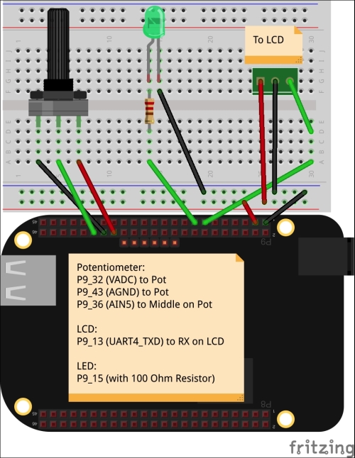
The potentiometer is connected via BBB's Analog-to-Digital Converter (ADC) pins. BBB's analog inputs can only tolerate a max of 1.8V; so, it's very important to use the dedicated analog voltage pin, pin P9_32 (pin number 32 of the connector P9), which provides this voltage. Do not connect the potentiometer to the normal 3.3V or 5V power rails, as this will damage the processor. We'll arbitrarily pick the analog input AIN5 on pin P9_36 as our input pin, and connect that to the middle lead or output of the potentiometer. Lastly, connect the last lead of the potentiometer to the dedicated analog ground pin, P9_34.
The LED and LCD both use 3.3V and the common ground. We need a serial transmit pin for the LCD, so we'll arbitrarily pick P9_13, which is the transmit for UART4. UART1 transmit on P9_24 or UART2 on P9_21 will also work fine.
Lastly, we need a GPIO to control the LED. Again, any will do, but I've picked pin P9_15. You'll need a resistor to limit the current to the LED. Sizing a resistor is straightforward using Ohm's Law; we just need to know the forward voltage drop and the max current of the LED. This information is found in the datasheet. If you are using SparkFun's 5mm Green LED, its max current is 20mA and has a forward voltage drop of 2.2V.
Ohm's Law states that voltage is equal to the current multiplied by the resistance, or V = IR. Subtracting 2.2V from 3.3V of our supply voltage, and dividing the resulting value by .020 Amps gives 55 Ohms. 55 Ohms isn't a standard value, but 56 is, so you can use this. But, you can always use a higher resistance value, and the LED will just be less bright. The resistor used in this project had a value of 100 Ohms.
There are some special considerations when wiring this project as it is meant to go inside an enclosure to provide the front panel. A stranded wire will bend and flex better compared to a solid core. Once settled in the enclosure, we wouldn't expect the wires to strain or move around, but they certainly will when you try to install the panel inside the enclosure! We also have a few options to wire our project to BBB. We could use jumper wires with male pins to insert into the female expansion headers, but these pins can come out easily, especially when you put your project into the enclosure.
We'll use SparkFun's BeagleBone Black Proto Cape, DEV-12774, to easily combine our circuit with BBB. This board breaks out power, ground, and other pin signals for expansion. It includes an EEPROM, which is not only useful if you want to have persistent data stored on your board but is also required if you are building a BeagleBone Cape, which will be discussed in detail in the next chapter. The advantage of a protoboard, especially the Beagle proto capes, is that we can solder male headers on the board and then use female terminated wires, which tend to connect a little better. Plus, by using the male headers, we can easily reuse the protoboard for a later project. However, these protoboards are not required, and if you are trying to save some money, with some creative wiring, you don't need one.
If you are using the protoboard approach, you don't have to populate all the headers either. Only the male pins that we need are soldered to the corresponding pads on the protoboard's P9 header. The way these protoboards work is that each pin is duplicated on the pads next to them. Solder the 100 Ohm resistor from P9_15 to the bottom of one of the male pins in the middle of the board. Then, connect a wire from the male pin to the positive terminal of the LED.
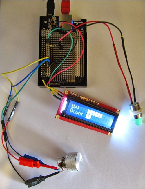
When complete, your project should look something like the following circuit diagram. We don't have the control software running yet, but you can see the LCD displaying the bandwidth usage. The following diagram doesn't have soldered connections to the potentiometer for the ease of testing, but instead uses IC Hooks. In a finished installation, you will want to solder the wires for a better mechanical and electrical connection.
The software for this project is freely available for download at https://github.com/jbdatko/beagle-bone-for-secret-agents/. In this section, we'll highlight the finer details of working with the existing libraries and outline the architecture of the project. The code uses many asynchronous callbacks from these libraries since there are several concurrent activities: the Tor bridge, the bandwidth knob, writing to the LCD, and blinking of the LED. To interact with the bridge, we'll use the Tor Stem library (https://stem.torproject.org/), and to interact with the hardware, we'll use Adafruit's BeagleBone Python library (https://github.com/adafruit/adafruit-beaglebone-io-python).
We installed the Stem library when we installed Tor; so, now we need to install the Adafruit BBIO library by performing the following commands:
sudo apt-get install build-essential python-dev python-setuptools python-pip python-smbus -y
sudo pip install Adafruit_BBIO
sudo pip install pyserial
The Adafruit library conveniently enables the device tree overlays, which are the files that describe the hardware configuration of BBB to the kernel, at runtime. Therefore, there is no need to manipulate the configuration via the sysfs as everything is handled in the Python library. The code models each hardware component as its own Python class. The LED modeled by the TorFreedomLED class is the most straightforward. We need the LED to blink; this is accomplished by toggling the output high, sleeping the executing thread briefly, and then toggling the output low to turn it off. To set up the GPIO, we only need to call GPIO.setup, by passing in the pin and the direction:
import Adafruit_BBIO.GPIO as GPIO
class TorFreedomLED(object):
  def __init__(self):
    self.pin = 'P9_15'
    GPIO.setup(self.pin, GPIO.OUT)

  def on(self):
    GPIO.output(self.pin, GPIO.HIGH)

  def off(self):
    GPIO.output(self.pin, GPIO.LOW)

  def blink(self):
    self.on()
    sleep(.5)
    self.off()
The LCD, controlled by the FrontPanelDisplay class, writes to the serial port, /dev/ttyO4, on BBB's UART 4 at 9600 baud. The LCD only receives information; therefore, we are only using the transmit lines from BBB. Commands are written to the attached microcontroller, which in turn drives the display. The datasheet, available on the SparkFun website, describes all of the commands. In general, the procedure is to move the virtual cursor on the display and then send the text.
Note
SparkFun has a more complete quick start guide on the serial LCD at https://www.sparkfun.com/tutorials/246. The example code is for an Arduino, but porting it to Python is straightforward if you follow the example of the bridge LCD in this chapter.
Similar to the GPIO example, the serial port in the Adafruit library can be used as follows:
import Adafruit_BBIO.UART as UART
import serial
class FrontPanelDisplay(object):

  def __init__(self):
    self.uart = 'UART4'
    UART.setup(self.uart)
    self.port = serial.Serial(port="/dev/ttyO4", baudrate=9600)
    self.port.open()
The display will automatically wrap lines if the text you are trying to display is longer than sixteen characters. Therefore, you have to manage the LCD to ensure that it displays correctly. For example, let's take a look at the display_graph method that is responsible for producing the bandwidth graph:
self.clear_screen()
up_str = '{0:<16}'.format('Up:   ' + self.block_char * up)
dn_str = '{0:<16}'.format('Down: ' + self.block_char * down)

self.port.write(up_str)
self.port.write(dn_str)
The first line clears the screen and resets the cursor to the top-left corner of the 16x2 display. Next, we format the two lines to display the graph using the special block character on the LCD. This line is left justified and is filled with whitespace up to sixteen characters. Finally, the lines are written to the LCD with the serial write methods. The cursor does not have to be reset between each line because after writing the first, it will be ready in the second line.
Lastly, the bandwidth adjust knob is modeled in the BandwidthKnob class. This class uses the ADC module and is also implemented as a thread. The analog input will always produce a value when read, and we will ratio this value to the available bandwidth for the bridge. The Adafruit library normalizes the values from 0.0 to 1.0; so, when the knob is at its midpoint, the call to ADC.read(pin) should return 0.5. There is some jitter in the analog signal, and we don't need a fine resolution on the bandwidth. Sampling once every second should suffice since we don't expect the knob to change frequently. We'll round up to the next whole number, which will give the knob ten discrete settings. The run method will report back to the caller, via a message queue, if the volume setting has changed. The calling thread can then update the Tor bridge bandwidth limits accordingly.
This code sample shows you how to set up the ADC on BBB with the Adafruit library and how to pass that result to a waiting thread with a message queue:
import Adafruit_BBIO.ADC as ADC
import threading
from time import sleep
from math import ceil, floor
import Queue
class BandwidthKnob(threading.Thread):

  def __init__(self, pin, *args, **kwargs):

    threading.Thread.__init__(self, *args, **kwargs)
    self.pin = pin
    self.setup_adc()
    self.kill = False
    self.prev_value = -1
    self.q = Queue.Queue()

  def setup_adc(self):
    'Load the Adafruit device tree fragment for ADC pins'
    ADC.setup()

  def read_value(self):
    return ceil(10 * ADC.read(self.pin))

  def stop(self):
    self.kill = True

  def run(self):
    knob = self.prev_value

    while knob != 0 and not self.kill:
      sleep(1)
      knob = self.read_value()
      if knob != self.prev_value:
        self.q.put(knob)
        self.prev_value = knob