What you saw in the previous chapter was a compendium of traditional animation techniques—traditional not in the Flash animation pioneer John Kricfalusi sense, but in the sense that they represent the basic tools animators working in Animate CC have used since time out of mind. Some tools don’t change simply because they don’t have to; they’re that useful. The exciting part is that Adobe introduced a new set of tools back in the Flash Professional CS4 era in addition to the time-tested tools. This double-whammy puts you in charge of the workflow that makes the most sense to you. Use one set or the other or combine them—the choice is yours. The best part is that because this is animation, you pretty much have to drink a broth of lukewarm poisonwood oils to not have fun while you’re working.
Here’s what we’ll cover in this chapter:
Motion tweening, using the Motion Editor and the Timeline panel
Advanced easing with the Motion Editor’s graphs
Manipulating motion paths
Using motion presets and copying motion from one symbol to another
Applying inverse kinematics (IK), including the Bone and Bind tools
IK tweening
The following files are used in this chapter (located in Chapter08/ExerciseFiles_Ch08/Exercise/):
01_Map.fla
02_EasePin.fla
03_CustomEasePin.fla
04_MultipleEasePin.fla
05_PixelDisposal.fla
06_MotionGuideSimple.fla
07_MotionGuideComplex.fla
08_MotionPreset.fla
09_Bones.fla
10_Springs.fla
11_BonesRigged.fla
12_Poses.fla
13_BadBind.fla
14_Worm.fla
15_Penelope.fla
The source files are available online at http://www.apress.com/us/book/9781484223758 .
Animating with the Motion Editor
Before there were websites like Digg and Delicious and before the term viral marketing became a cliché, people actually emailed hyperlinks to each other. Some of the earliest must-share Flash animations include Alex Secui’s “Nosepilot” ( http://animation.nosepilot.com/ ) and JoeCartoon.com’s “Frog in a Blender” ( http://joecartoon.atom.com/cartoons/67-frog_in_a_blender ), shown in Figure 8-1. These are classics that still entertain after more than a decade, and they were created with shape tweens and what are now called classic tweens, along with a good dose of elbow grease.
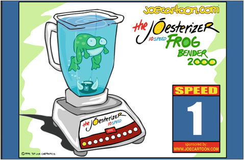
Figure 8-1. A scene from Joe Cartoon’s infamous “Frog in a Blender” from 2000, which was among the first Flash animations to go viral
Clearly, the existing animation tool set—the Timeline panel and its trusty sidekicks, the Free Transform tool , the Transform panel, and a handful of others—is perfectly adequate to get the job done. But just as it can be good in a relationship to agree on acceptable word pronunciations (toe-may-toe and toe-mah-toe come to mind), it will be good for your relationship with Animate CC to consider other ways to animate content. You’re about to start flirting with the Motion Editor.
Introduced in Flash Professional CS4, the Motion Tweens provided a second non-ActionScript paradigm for moving things from here to there. It’s an alternate mechanism to the classic tweens and shape tweens that are carried out in the Timeline panel . In Chapter 1, we gave you a drive-by Motion Editor overview, and you’ve seen glimpses of it in a handful of other chapters. Now that you have read Chapter 7 and have experimented with the various details and nuances of the traditional tweening model, the differences between the old and the new will become abundantly clear.
Since that time, there has been a huge surge of interest in the new-style motion tweens—and there’s good reason for that, as you’ll see. People have begun to ask, “Which approach is better?” We’re compelled to reply with the only legitimate answer there is: the best approach depends entirely on whatever works best for the project at hand.
Think of it like this: you’ve been using a conventional oven for years, when suddenly a newfangled microwave shows up on your doorstep. It’s small and sleek and even has a rotating platter. Grinning, you carry it into the kitchen, plug it in, and slide in some of the goulash leftovers from last night. Two minutes and 20 seconds later—ding! —you have an instant lunch. “Let’s try that again,” you think, and put in a glass of milk with Hershey’s syrup—45 seconds later, instant hot chocolate. Does it get any better? From this day forward, it takes you only 3 minutes to get fresh popcorn. In many ways, life has gotten easier, but you can bet your bottom BBQ that the conventional oven isn’t leaving its venerable perch. There’s no way the microwave bakes a loaf of homemade bread, for example. Then again, a medium rare steak done on the BBQ is far better than one done in a skillet.
Clearly, you’ll want the best of both worlds. And your kitchen is big enough for it.
Getting Acquainted: Scaling and Moving
Let’s take a comprehensive tour of the Motion Editor, covering all the basics. Portions of this will feel like a review after Chapter 7, but it’s important to understand how the mechanics of motion, scaling, and distortion are distinct from the machinery of classic tweens. You won’t be seeing any shapes, by the way, until much later in the chapter. The Motion Editor deals exclusively in symbols and text fields, just as is the case with classic tweens.
In this case, you’ll be creating motion tweens, which look and behave like their classic cousins. The differences come in how they’re made and how you can edit them, as you’ll see in the following steps:
Open the 01_Map.fla file found in the Chapter 8 Exercise folder. When it opens, you will notice a pin on a map. The pin you see on the stage is the Pin graphic symbol found in the Library.
Right-click on Frame 1 of the Pin Layer and select Create Motion Tween. This converts the layer into a tween layer and makes it available to the Motion Editor. (Alternatively, you can click frame 1 of the Pin layer and select Insert ➤ Motion Tween.)
When you apply the motion tween, several things happen at once: the single frame stretches out to a 24-frame span and the span turns light blue when deselected. Why 24 frames? The default length is 1 second, so what you are seeing is one second of animation on the timeline. If you need more time, roll the mouse pointer to the end of the span. When the mouse pointer changes to a double-arrow, click and drag to the right, extending the tween to frame 70.
With the playhead at Frame 70, drag the pin down and to the right where the two big white streets intersect. What you have is a Pin, Figure 8-2, that moves in a straight line. Let’s change that, shall we?
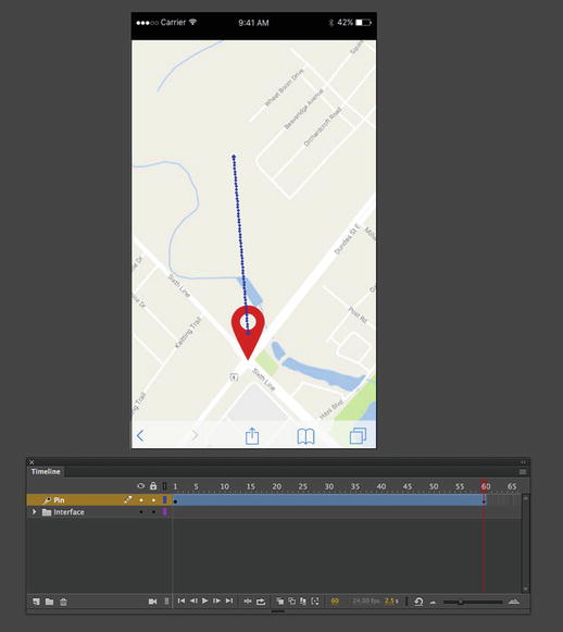
Figure 8-2. A motion tween has been applied to the Pin symbol
At this point we have played with the Motion Path by dragging a point on the path. There is another method. Here’s how:
Open the Motion Editor by double-clicking anywhere between the two keyframes. This time—provided you haven’t deselected the tween layer—you’ll see the various grids and input controls shown in Figure 8-3.
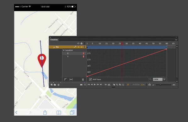
Figure 8-3. Applying a motion tween activates the Motion Editor for that layer
Removing a motion tween is as easy as applying one. Right-click (Windows) or Control+click (Mac) the tween layer. Select Remove Tween, and the layer turns gray again. If you have removed the tween, undo it.
It’s time to take a look at the some of the differences between motion tweens and classic tweens. The key is to be aware the Timeline and Motion Editor are so integrated in Animate CC that they are actually fond of each other. You might even say they’re connected at the hip. When you apply changes to a tween layer in one view, you’ll see the changes are instantly reflected in the other.
In the Timeline panel, drag the playhead to frame 20. Use the Free Transform tool or the Transform panel to make the symbol much wider than it should be.
When you widen the symbol, you’ll see a black diamond appear under the playhead in frame 20, as shown in Figure 8-4. Notice the diamond is a tad smaller than the dot that represents the default keyframe in frame 1. The difference in shape and size tells you this is a property keyframe, which is just “tween-layer–speak” for a keyframe.
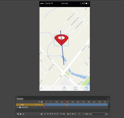
Figure 8-4. Tween layer changes are stored in property keyframes
Open the Motion Editor by double-clicking anywhere in the tween span. Scroll vertically until you find the Scale X grid, as shown in Figure 8-5, and then scroll horizontally until you find the property keyframe that was automatically added when you changed the symbol’s width in the Timeline panel.
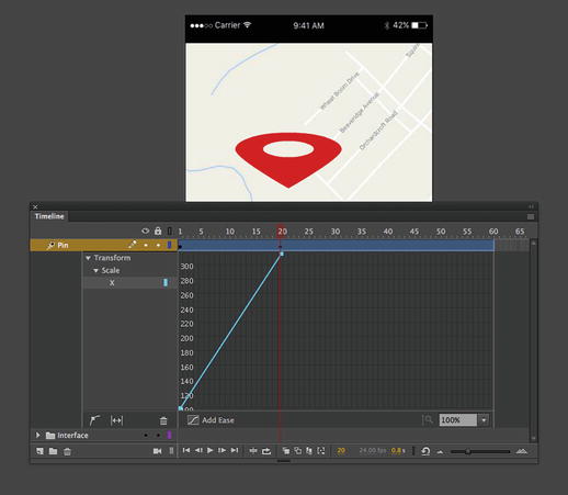
Figure 8-5. The Motion Editor shows property changes in detailed, collapsible graphs
In the Motion Editor and select Transform ➤ Scale ➤ X.
The graph depicted shows a change in x-axis scale; that is—assuming the symbol isn’t rotated—the width. The numbers along the left side stacked vertically show values that pertain to this property, which are percentages of scale. The numbers along the top show frames, which equate to changes over time.
Follow the slanted line in the graph from bottom left up toward the upper right. It shows that the selected symbol began at a 100 percent width—the 100 is partially obscured by the slanted line’s left point—and was stretched to over 200 percent over a span of 20 frames
This is considerably more detail than you get with classic tweens. We’ll come back to this graph concept in just a moment. First, back to the kissin’ cousin.
In the Timeline and with the playhead still in frame 20, drag the Pin symbol to the upper-right corner of the stage, as shown in Figure 8-6. At this point, you’ve tweened three distinct properties: Scale X, the X position, and the Y position.
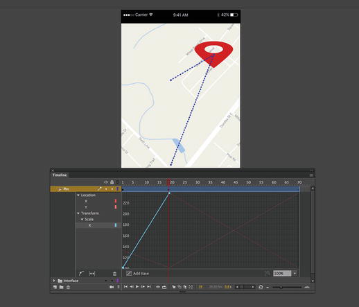
Figure 8-6. Expanded graphs in the Motion Editor can make motion data easier to see
Note that the property keyframe, from this view, is still just a small diamond at frame 20 in the timeline. All you can tell at a glance is that something has changed. But even if there’s less detail here, the two views are in agreement, and the Timeline view does give you a summary. Later in this chapter, in the “Changing Duration Nonproportionally” section, you’ll see how the Timeline panel’s abridged view actually makes it easier to update numerous property keyframes at once.
Naturally, you can see the changed properties directly on the stage, not only because the symbol itself is stretched and moved but also because of that dotted line that connects the current position of the symbol (specifically, its transformation point) to the position it held in frame 1. If you count them carefully, you’ll see 20 dots along the line, which represent the 20 frames in this tween span. The dots are all evenly spaced apart, which tells you the tween has no easing applied.
The vertical values in these graphs, along with the tooltips, change depending on the property represented. For example, the Location X graph starts just under 160 on the left side (not 100, like the Scale X graph), because the symbol is positioned at 156.95 pixels on the x-axis in frame 1. On the right side of the slanted line, the Properties panel shows a value of 291.95, because that’s where the symbol is positioned on the x-axis in frame 20. The point to take away from this is that these graphs are adaptable, and they change to suit the values of the property at hand. The X graph shows pixels, Scale X shows percentages, Rotation Z and Skew X show degrees, and so on.
Applying Easing
It is a fact of life, when it comes to objects in motion in Animate CC, that easing needs to be applied. Objects in motion don’t automatically stop and start. Instead they accelerate and decelerate, which is the purpose of easing. The really neat aspect of the Motion Editor is that you can apply eases from the Properties panel or right in the Motion Editor. Here’s how:
Open the Timeline panel and select the keyframe at frame 20 of the timeline.
In the Properties panel; twirl down the Ease twirlie, if necessary; and scrub the hot text value—0, by default—slowly toward the left. Scrub it to approximately -10, and then let go. Scrub again to -20 or so, and then let go. Scrub again to -30, -40, and so on, until -100, which is a full ease-in.
As you scrub and release in small increments, you’ll see that the dots, which were evenly distributed after Step 12, begin to cluster toward the lower left, as shown in Figure 8-7, which represents the beginning of the tween. You just applied an ease in, so it makes sense that the dots are packed more closely at the beginning of the tween.
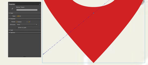
Figure 8-7. Easing can be applied using the Properties panel
In classic tweens, easing takes effect only between keyframes. In motion tweens, easing is distributed over the frame span of the whole tween, independent of property keyframes. This is a significant departure from the classic model.
Close your file without saving it.
Easing applied to a motion tween with the Properties panel is the same sort of easing applied to classic tweens, excluding the special-case Custom Ease In/Ease Out dialog box , discussed in Chapter 7. To get to the exciting stuff, you’ll need the Motion Editor, and advanced easing merits its own section.
Easing with Graphs
When it comes to the Motion Editor, the concept of easing ascends to a whole new level. For classic tweens, the Custom Ease In/Ease Out dialog box is the only thing that came close to sharing similar functionality, yet it provides little more than an introduction. The Custom Ease In/Ease Out dialog box associated with a classic tween is a good place to start but the real power of easing is found in the Motion Editor.
A powerful feature of the Motion Editor is that it overcomes a subtle, but significant, limitation of the Custom Ease In/Ease Out dialog box : classic easing, for whatever property is under consideration, begins at a starting point of 0 percent and ends at a destination point of 100 percent. If you’re moving a symbol from left to right—for example, from 25 pixels to 75 pixels—a classic tween begins at its starting point of 25 pixels (0 percent of the destination) and ends at 75 pixels (100 percent of its destination). Normal easing lets you adjust the acceleration and deceleration between those two immutable points. The Custom Ease In/Ease Out dialog box lets you adjust the velocity with greater control, thanks to Bézier curve handles. In fact, by adding anchor points, you can even opt to arrive at the destination point early, then head back out again and return later, as demonstrated in Chapter 7 with the bouncing mallet exercise. But in the end, there must always be a final anchor point. With classic easing, the final anchor point is always tethered to the 100 percent mark (see Figure 8-8).
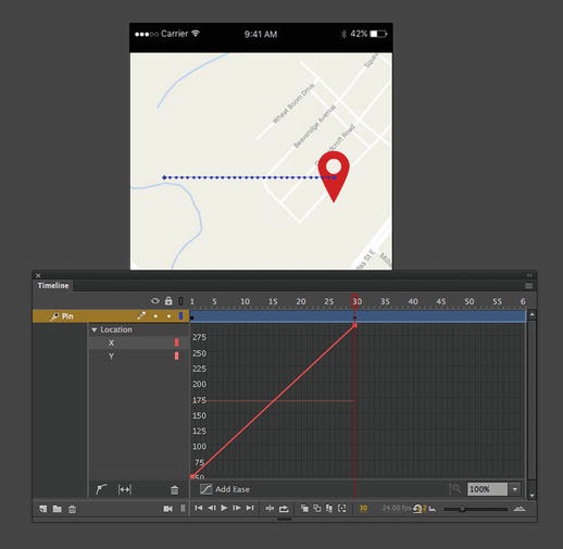
Figure 8-8. Without easing, the graph shows a straight line
Unimpeded in this regard, the graphs of the Motion Editor can end up where you like. A custom ease can start at its beginning point of 0 percent, travel three quarters of the way to its destination, dance around a bit, and then return all the way to the beginning.
This freedom within the property graphs is a powerful tool, which is generally a good thing. But as anyone into Spider-Man will tell you, “With great power comes great responsibility.” Everything comes at a cost, and the price here is that the banished 100 percent restriction can occasionally be disorienting, especially when eases continue past the last property keyframe in a tween span. Let’s take a look.
Built-In Eases
If you’ll pardon the pun, we’re going to ease into this. Let’s start with the built-in eases:
Open the 02_EasePin.fla file in the Chapter 8 exercise folder. Our Pin is back, and this time the symbol has been given a 60-frame motion tween that moves it from the left side of the stage (frame 1) to the right side (frame 30) and then lets it sit in place until frame 60.
Select the tween layer or the symbol by clicking it, and then open the Motion Editor. Find the X graph and notice the straight line from the beginning point (bottom left) to the destination point (upper right), as shown in Figure 8-8. Because no other X changes occur after frame 30, there are only two property keyframes in the graph.
Notice the button at the bottom of the graph that says Add Ease? Click it to enable easing, and from the drop-down list select Simple ➤ Slow. At this point, you’ve applied an ease, which is the dashed line on the graph shown in Figure 8-9.
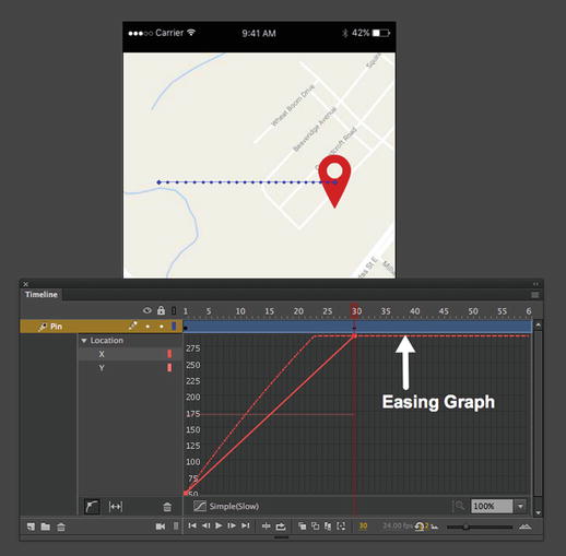
Figure 8-9. Apply an ease and the Motion Editor shows it to you
Press Enter (Windows) or Return (Mac) and watch the Pin move from left to right.
If that doesn’t look like easing to you, you’re right. Selecting Simple (Slow) isn’t enough. You need to choose a percentage for that ease, which affects its strength. Think of it as a faucet—applying the ease means you’ve paid the water bill, but you won’t see water until you turn on the faucet.
Scroll down to the bottom of the Motion Editor and click the Ease button. When the panel opens, you’ll see the reason why Simple (Slow) appeared in the X graph’s easing drop-down list.
Scrub the hot text as far right as it will go, changing the default 50 to 100. As you scrub, you’ll see a solid line, representing the ease, begin to curve in the graph, as shown in Figure 8-10.
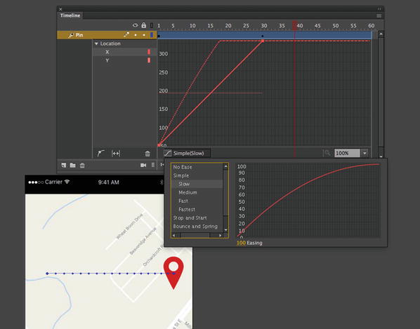
Figure 8-10. Change the default from 0 to 100, and the curve appears
This particular graph changes the Simple (Slow) ease itself, which is comparable to changing a symbol inside the Library. As you learned in Chapter 3, changing a Library symbol means that every instance of it is changed on the stage. The same goes for these eases. You also might have noticed the mascot shift around on the stage as the ease is applied to the motion.
Scroll back up to the X graph, and you’ll see that the ease is now superimposed over the line that represents the symbol’s x-axis movement. To get a better view, click the left side of the X graph, and click the fit to view button. All 60 frames are displayed in the graph.
Press Enter (Windows) or Return (Mac) again to preview the movement, but prepare yourself for disappointment: it still doesn’t look like much of an ease.
The reason for this is that motion tween eases are applied to the full span of the tween. In this case, the full span is 60 frames, while the only visible change occurs between frames 1 and 30.
Click the upper-right red property keyframe in the Motion Editor graph and, holding down the Shift key, drag the keyframe to the right until you hit frame 60. Doing so turns the dashed line to a gentle curve, as shown in Figure 8-11. The tooltip lets you know which frame you’re on, and the Shift key constrains your movement.
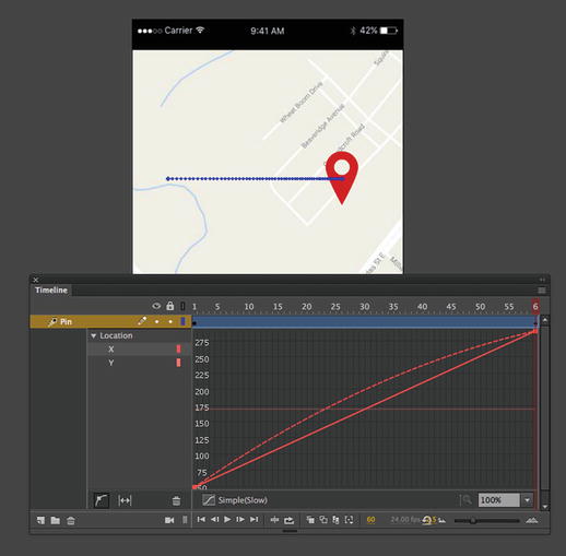
Figure 8-11. Keyframes can be moved from inside a graph
If you don’t use the Shift key while you drag, it’s easy to slide the keyframe up and down, even if you intend to move only to the right, which increases the duration between this keyframe and the one before it. Why is it a bad thing to slide up and down? Actually, it isn’t. Sometimes, you might want to do that, and it’s good to know you have the option. Sliding up and down changes the property’s destination point. In this case, because you’re dealing with x-axis movement, it means that even from this graph, you could push the symbol farther to the right on the stage (slide the keyframe higher) or back toward the left (slide the keyframe lower).
The visual result of a property’s destination point depends entirely on what the property represents. In the Y graph, the destination point affects the symbol’s vertical position. In the Rotation Z graph, it affects the symbol’s rotation. If you add a color effect or filter, the destination point determines how much of that effect is applied.
Press Enter (Windows) or Return (Mac) again. Because the solid and dashed lines’ final anchor points meet, you’ll see the full Simple (Slow) ease.
Using the Shift key again, drag the right property keyframe back to frame 30.
Open the Eases area in the Motion Editor, and let’s add a bounce to the Pin. Choose Bounce and Spring ➤ Bounce, as shown in Figure 8-12.
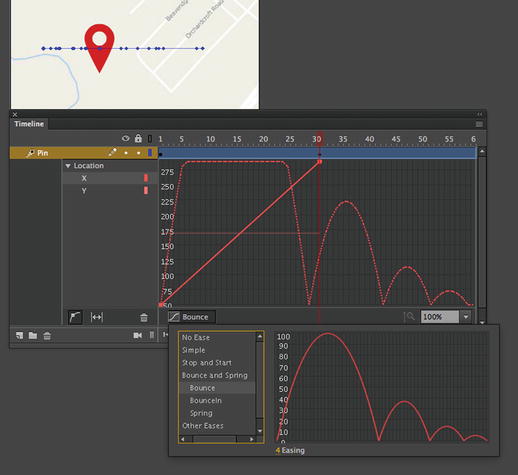
Figure 8-12. Animate CC lets you change the ease to meet your needs
By default, the Bounce ease’s hot text is set to 4, which makes the four bounces depicted in its graph. Change the hot text at the bottom of the Ease pane to 3 to reduce the number of bounces to three.
Adding an ease to the Eases area makes that ease available to all the property graphs in the Motion Editor. Eases can be applied and changed for each property individually by using that property’s drop-down menu and/or check mark. Eases can be applied and changed for whole groups of properties. Add as many eases as you like, including multiple custom eases.
As you may have guessed, you can use the No Ease button at any time in the Eases area to remove an ease from consideration for all drop-downs.
By adding the Bounce, three interesting things happen when you make this change. First, because you moved the property keyframe back to frame 30, part of the Bounce ease is clipped, as you can see in the flattened hump of the first bounce—between frames 6 and 27—in Figure 8-12. The second interesting thing is, though the graph may have developed “bumps,” they are only on the x-axis, meaning the bumps represent lateral movement, which explains why the motion path on the stage doesn’t change. The third interesting thing becomes apparent when you preview the ease.
Press Enter (Windows) or Return (Mac), and watch the Pin slam to the right side, pause for a moment (that’s the clipped first bounce), then resume its rebounding course, and finally end up back on the left side of the stage!
With motion tweens, easing can completely override the actual property represented by the solid line in the graph. Without the ease, this is a simple left-to-right movement. With easing, this could be that, but as you’ve seen, it can just as easily change the destination point to one quite outside of Kansas.
We chose physical movement to illustrate the mechanics of motion tween easing, because a change in position correlates well with the lines and curves on the graph. Be aware that this concept applies in exactly the same way to rotation, scaling, skewing, color effects like alpha and tint, and filters like Drop Shadow and Blur.
Shift-drag the right property keyframe back to frame 60. Verify that all three bounces are now visible in the X graph.
Press Enter (Windows) or Return (Mac) to view the full, smooth three-bounce easing of the Pin.
Creating Custom Eases
Even after seeing more than a dozen built-in eases, you might be wondering whether you can create your own. The answer is yes, and it’s pretty easy. Best of all, custom eases are saved with the FLA, which means you don’t need to commit all your easing finagling to memory. Your custom eases will be there when you reopen your files in the morning, and even better, once they are added to the Eases area, you can apply (and reapply) custom eases to any property, just like built-in eases. Here’s how:
Open 03_CustomEasePin.fla in this chapter’s exercise folder. Again, we start you with a basic left-to-right motion tween, this time over a full 60 frames.
Click the tween layer (layer 1) or the symbol, and then open the Motion Editor. Scroll down to the Eases area, click the + button, and select Custom from the context menu. This creates a Custom graph for you, so let’s take a look.
What you see is a line with run-of-the-mill Bézier curve handles. The anchor points and handles operate very much like those for normal drawings with the Pen tool, and we encourage you to experiment.
To create a custom ease click the “Add Anchor Point on Graph” button. When you move the cursor over the graph it changes to a Pen Tool and, to add the anchor point, click the mouse. To remove an anchor, just roll the mouse over the anchor point to be removed. You will see a small box appear under then cursor. This technique removes any anchor point but the first and last (there must always be a beginning and destination point). Use the Alt (Windows) or Option (Mac) key while clicking to convert a curve anchor point to a corner anchor point and vice versa. See Figure 8-13.
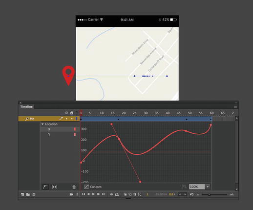
Figure 8-13. Use the pen to create custom eases in the Motion Editor
When you finish, scroll to the X graph, and select your custom ease from the X property’s drop-down menu. Press Enter (Windows) or Return (Mac) to preview the effect.
Close your file without saving the changes.
Applying Multiple Eases
It may not immediately sound ambiguous, but the phrase “applying multiple eases” can actually be interpreted in a variety of ways. To be sure, you can apply numerous eases to a given motion tween—one separate ease for each tweenable property is perfectly acceptable. Give your X a bounce, your Y a Simple (Slow), your Rotation Z a custom ease, and so on, down the line. What you can’t do is to apply more than one ease between property keyframes. If you’ve used previous versions of Animate CC or Flash, this may take some getting used to, which is why we’ve stressed that motion tween easing applies to the full tween span, not to the span between property keyframes.
To follow one sort of easing with another sort within the same tween layer, you’ll need to use more than one tween span. Here’s how:
Open 04_MultipleEasePin.fla in this chapter’s exercise folder. This time, to mix it up, we prepared a vertical motion tween for you.
Open the Motion Editor and, with the X Location graph selected, add a Stop and Start (Medium) ease. When its graph appears, scrub its hot text to the right until it says 100.
Select the Y graph, and select Stop and Start (Medium) in the easing drop-down menu. Press Enter (Windows) or Return (Mac) to preview the ease, which makes the Pin look as if it were being dragged downward with two heaves of a rope.
Select the Timeline layer. Right-click (Windows) or Control+click (Mac) the tween span, and select Copy Frames from the context menu. Now right-click (Windows) or Control+click (Mac) frame 31, and select Paste Frames. Just like that, you’ve created a twin of the original animation, complete with its easing.
Right-click (Windows) or Control+click (Mac) the second tween span, and select Reverse Keyframes. Preview the animation again, and this time, the Pin gets heaved up and then heaved down again. Even though the motion is reversed, the tween is still the same for both tween spans.
Open the Motion Editor, and change the second span’s Y easing from Stop and Start (Medium) to Spring. Preview the animation, and you’ll see the Pin getting heaved up and then suddenly fall and “sproiiing” to a halt.
Same tween layer, two tween spans—that’s how you get two or more types of easing in the same layer. As an aside, notice that the Pin doesn’t come to a rest at the bottom of the stage. That’s because the Spring ease is one of those whose destination point doesn’t stop at 100 percent.
Managing property keyframes
Before we turn you loose on a rather interesting project, there is one final issue to cover: property keyframes. The small diamonds you see on a motion layer are called property keyframes, and they can be managed in one of two areas: through the Timeline or through the Motion Editor . The thing you need to know is that each one has its own way of handling the details. When it comes to exercising fine control of keyframes, the Motion Editor is your best bet, but there are a few circumstances where using the Timeline panel definitely makes your life simpler. We’ll get to that in a moment, but let’s start with a diamond:
Open the 05_PixelDisposal.fla file from the Chapter 8 exercise folder. When it opens, you will see a character on a sign tossing a red pixel into the trash. If you scrub across the timeline, the property keyframe at fame 35 is where the pixel changes direction, rotates, and starts to shrink.
While you are in the Timeline panel, the only way to move from keyframe to keyframe is to scrub the playhead. Go ahead and scrub to frame 40.
Right-click the tween layer at frame 40, and select Insert Keyframe ➤ Position from the context menu, as shown in Figure 8-14. A property keyframe will appear at frame 40.
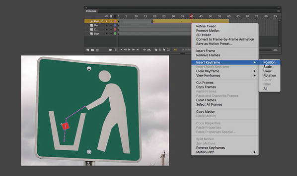
Figure 8-14. Property keyframes can be added from the Timeline panel
Select the Red cube symbol, and move it downward. As you saw earlier in the chapter, property keyframes are created for you automatically in the current frame when you change a symbol’s position, scale, rotation, or the like. What you learned from step 3 is that it’s still perfectly OK to create your keyframe first.
Switch back to the Timeline panel, and right-click (Windows) or Control+click (Mac) again on frame 40. Note that you have options for clearing keyframes and also determining which property keyframes to display in the Timeline panel.
Don’t be fooled by the Clear Keyframe choice! You would think, because Insert Keyframe inserts the desired keyframe(s) in the current frame, that Clear Keyframe would, like its Classic Tween brother, follow suit and remove only keyframes in the current frame. This is not so. By choosing Clear Keyframe, you’re removing all property keyframes in the current tween span. If you select Clear Keyframe ➤ Rotation, for example, you remove all property keyframes in the Motion Editor’s Rotation Z graph, regardless of in which frame they appear.
Once you see these features and understand them for what they are, you’ll surely find them useful, but the Motion Editor does more.
Open the Motion Editor, and scrub the playhead along the Motion Editor’s timeline. You get the same sort of preview as the Timeline panel. The difference is that the Motion Editor, Figure 8-15, also gives you the ability to change properties … by the numbers.
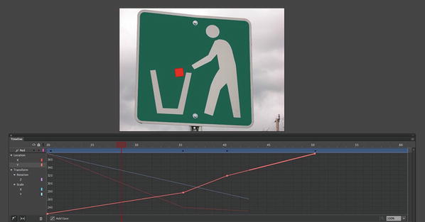
Figure 8-15. In the Motion Editor , keyframes can navigated, added, and removed with this widget
Scrub to frame 40, and click the Y Location point on the graph. Keep an eye on the cursor. It will change to a box when over the keyframe. That change tells you that you can move this keyframe.
Drag the keyframe upwards to about 360 on the graph. Notice how the location changes on the stage?
Select the Add Anchor Point button and move your mouse elsewhere in the Y graph. The cursor changes to the pen and you can add an anchor point (Keyframe) when you click the mouse, and then hold down the Ctrl (Windows) or Cmd (Mac) key while you hover over one of the line segments. As shown in Figure 8-16, the cursor turns into a pen with a plus sign, which indicates you can click to add a new keyframe.
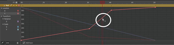
Figure 8-16. Keyframes can also be added and removed with the mouse
With the keyframe selected, switch to the Pen tool, hold down the Alt (Windows) or Option (Mac) key, and hover over the new keyframe. The cursor turns into an upside down V. Click, and this converts the anchor point into a curve anchor, which can be adjusted with Bézier handles. Just drag the cursor to see the handles. The effect of these handles on the X and Y graphs isn’t always obvious, but for many properties, it gives you a “quick-and-dirty” custom ease.
Switch to Transform ➤ Rotation and select the Z-Axis. The middle keyframe up and to the right. As you drag the point watch the rotation of the cube as you move the anchor point up or down on the graph and as you move the handles on the curve.
Press Enter (Windows) or Return (Mac) to preview the animation, and you’ll see that the symbol rotates farther than it did before—you’ve pushed it past its original destination, to approximately 160 percent—and then eases back the Rotation Z setting in the property keyframe at frame 50. Don’t close this file just yet; we are going to work some further “magic” on it in the next exercise.
As helpful as the Motion Editor is, sometimes less is more. When you want to compress or expand the duration of a tween span, for example, the Timeline panel is the only way to do it, if you want to do it proportionally. If not, you could use either panel, but the Timeline panel makes it easier.
Changing Duration Proportionally
The animation in the PixelDisposal.fla you were just using spans 60 frames. At 24 fps, that’s approximately 2.5 seconds, which may or may not be what you want. To change a tween span’s duration proportionally, you’ll need to use the Timeline panel . Here’s how:
Move your mouse to the right edge of the tween span. You’ll see the cursor turn into a double-headed arrow, as shown in Figure 8-17. Click and drag toward the left. For example, shorten the tween span so that it ends at frame 50. Notice that all four property keyframes are still in place, and, proportionately speaking, are the same relative distance from each other as before.
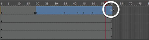
Figure 8-17. Drag the tween span to shorten or increase a tween’s duration
Click and drag the right edge tween span so that it ends at frame 59. Now release and drag the right edge of the tween span to frame 60.
This time, the property frames are nearly back to their original places, but some are slightly off. That makes sense, because frame 59 is an odd number, and Animate CC had to make a decision on how to shift the frames to compensate.
To get the property keyframes back to frames 30, 40, 45, and 50 exactly, you’ll need to use a different approach. If you’re into tedium, you could switch to the Motion Editor and visit every property graph in turn, sliding numerous anchor points while holding the Shift key. The middle keyframe, especially, would give you a headache, because it affects the X, Y, Rotation Z, Scale X, and Scale Y graphs. There’s an easier way, and we describe it in the very next paragraph.
Changing Duration Nonproportionally
Sometimes you’ll want to change the duration between property keyframes, which may or may not incorporate a change in span duration. You could do this with the Motion Editor , visiting each relevant graph and moving property keyframes individually, or you can update the keyframes in several graphs at the same time. For that, use the Timeline panel . Here’s how:
Continuing with 05_PixelDisposal.fla file you have been working on and still in the Timeline panel, hold down the Ctrl (Windows) or Cmd (Mac) key and click the keyframe closest to frame 35. Notice that holding down Ctrl (Windows) or Cmd (Mac) allows you to select a single frame in the tween span, rather than the whole span.
Now that you have a single property keyframe selected, release the Ctrl (Windows) or Cmd (Mac) key, and then click and drag the selected keyframe left or right along the timeline. Doing this effectively selects all the anchor points for the current frame in the Motion Editor and lets you move them as one.
Motion Paths
In Chapter 7, we showed you how to animate a butterfly along a special kind of layer called a motion guide. As you discovered, it was a path that could be as intricate as you wanted and allows a symbol to appear to meander around the screen following loops and curves that you drew with the pen tool. This capability is also possible in the Motion Editor . When you go this route, you don’t use a guide, you use a path that is hardwired right into the motion layer. In fact, you have already seen this feature but never really got a chance to use it. Your opportunity has arrived.
Manipulating Motion Paths
The most fascinating thing about this feature of the Motion Editor is you don’t need to use the Motion Editor. Motion paths are best manipulated through the Timeline panel . Here’s how:
Open the 06_MotionGuideSimple.fla file from this chapter’s exercise folder. When it opens, you will see that our pixel disposer has three pixels to toss into the trash bin. Turn off the visibility of the Green and Blue layers by clicking the eyeball icon on the layer strip.
Scrub through the timeline, and you will see that red cube fall to the bottom of the wastebasket. Did you catch the problem? The cube seems to move over the bin before hitting the bottom. You can see this in Figure 8-18 if you follow the motion path. Let’s fix that.
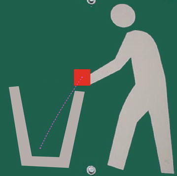
Figure 8-18. The motion path shows you the “line” an object in motion will follow
Drag the playhead somewhere between the two keyframes and switch to the Selection tool. Hover near the motion path, and a curve will appear under the arrow. Click and drag the path to the left. As you do, the path will curve, as shown in Figure 8-19.
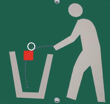
Figure 8-19. Motion paths can be manipulated on the stage
Turn on the visibility of the Green layer and switch to the Subselection tool.
Click on either anchor point and drag the Bézier curve handles, as shown in Figure 8-20 to increase the range of the curve. As you can see, motion paths can be treated as vector objects.
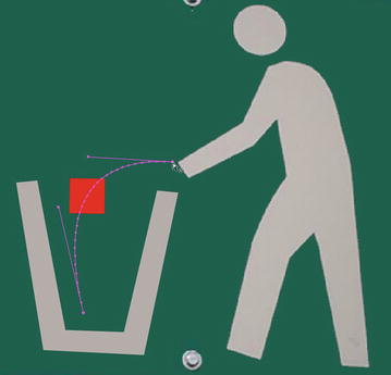
Figure 8-20. Use the Subselection tool to treat the path as a vector line
This technique works only if the path has a curve.
Not only can you reshape the motion path, but you can also move it, rotate, skew it, and treat it like any other shape or object on the stage. Let’s keep experimenting.
Turn on the visibility of the Blue layer and select it. Now turn your gaze to the Properties panel. Twirl down the Path options. Scrub across the X, Y, W, and H values, and you will see that you can move and resize the path. Impressed? Hang on—it gets better.
Open the Transform panel. Get your hand off the mouse because this one is a bit trickier. You need to select the path here, not the object, or Animate CC will think it has to transform the blue cube instead.
Use the Selection tool to click anywhere along the path. Now scrub across the Transform panel’s Rotate value. The path will, as shown in Figure 8-21, rotate around its start point.
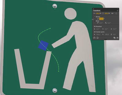
Figure 8-21. Use the Free Transform tool, Transform panel or press Ctrl (Windows) or Cmd (Mac) to transform a motion path with your mouse
Experiment with the Width, Height, and Skew properties in the Transform panel.
If you want to do it yourself and not use numbers, switch to the Free Transform tool and select the path. As shown in Figure 8-21 you can manipulate the path just as you would with a movieclip of graphic symbol. If you don’t want to switch tools and do this strictly with the mouse, select the path with the Subselection tool and press Ctrl (Windows) or Cmd (Mac).
Don’t forget the Alt (Windows) or Option (Mac) key while you make these transformations with the mouse. Without it, transformations pivot around the bounding box’s center. With Alt (Windows) or Option (Mac), transformations pivot along the opposite corner or edge. In either case, the Ctrl (Windows) or Cmd (Mac) key is required to produce the bounding box.
Using Advanced Motion Paths
In Chapter 7, the butterfly went on a pretty wild ride—nothing like the tame Bézier curves you’ve seen so far in this chapter. You can do the same thing with the new tweening model, and you still don’t need a motion guide layer. Here’s how:
Open 07_MotionGuideComplex.fla in this chapter’s exercise folder. You’ll see a slightly different finished version of the butterfly MotionGuide.fla exercise from Chapter 7, including a classic tween directed by a motion guide layer. Your job—and it’s an easy one—is to convert that complex motion guide into a motion path.
Right-click (Windows) or Control+click (Mac) the flutter by (motion guide) layer, and deselect Guide from the context menu. This converts that layer back to a normal layer.
Using the Selection tool, double-click the wavy line to select the whole thing, and then cut the curves to the clipboard (Edit ➤ Cut).
Right-click (Windows) or Control+click (Mac) the classic tween and select Remove Tween from the context menu.
Right-click (Windows) or Control+click (Mac) again and select Create Motion Tween.
With the tween layer selected, paste the wavy line into the layer by selecting Edit ➤ Paste in Place. That’s all there is to it! If you like, delete the now-empty flutter by layer.
Click the tween layer again. Use the Properties panel to select or deselect Orient to path, which behaves as it did for the classic tween version.
Motion Tween Properties
As you’ve seen throughout this book, the Properties panel is the most versatile panel in your arsenal, simply because it changes to reflect whatever object is selected. When you’re dealing with motion tweens, there are two things the Properties panel lets you manipulate: the symbol and the tween itself (that is, the motion path). Some of these properties are the ones you see for classic tweens, but they don’t all apply for motion tweens.
Let’s take a look. Open any of the files you’ve used to far, and make sure a motion tween is applied to at least one symbol. Select the tween span, and you’ll notice the following properties in the Properties panel:
Ease: This applies the Motion Editor’s Simple (Slow) ease to the full frame span selected. You can adjust this ease’s hot text to a value from -100 (ease in) through 0 (no ease) to 100 (ease out).
Rotate [x] time(s) + [y]°: This is comparable to the Rotate drop-down for classic tweens and manages symbol rotation. The two hot text values let you specify the number of full rotations ([x]) and degrees of partial rotation ([y]).
Direction: Once rotation numbers are configured with the previous property, you can choose clockwise (CW), counterclockwise (CCW), or none to determine the direction of those settings or cancel them.
Orient to path: This check box applies only to orientation along a motion path.
X, Y, W (Width) and H (Height): These reposition or transform a tween span’s motion path.
Sync graphic symbols: Human beings still have an appendix, but modern science still hasn’t definitively figured out what it’s good for, and the same goes for this property. Given its name, it’s presumably the motion tween equivalent to the classic tween Sync property discussed in Chapter 7. With motion tweens, symbol synchronization happens automatically, whether or not this property is selected. As you’ll see in the next section, this feature is moot in any case, because motion paths can be reassigned to any symbol you like.
The other motion tween–related Properties panel settings depend on the symbol itself. For movieclips, your configuration options for motion tweens are the same as those for classic tweens. Some properties—such as position, scale, and rotation, and even color effects such as alpha—are tweenable. Others, such as blend modes, are not. These are consistent across the board when you’re dealing with movieclips. It’s when you’re using graphic symbols that you need to be aware of a few limitations.
The limitations involve the Loop , Play Once, Single Frame , and Frame options in the Properties panel’s Looping area . These properties apply to classic tween keyframes as discussed in Chapter 7. For motion tweens, they apply only to the tween span’s first keyframe. They’re ignored for property keyframes. The long and short of it is that you can set the Loop , Play Once , and Single Frame drop-down options and Frame input field once for a given motion tween—and Flash will obey your command—but only once for that tween span. Change these settings at any frame along the span, and the settings are changed for the whole span.
Even though we’re focusing on symbols in these paragraphs, bear in mind that motion tweens can also be applied to text fields.
One final note. Like classic tweens, motion tweens can accommodate only one symbol per tween span. In fact, motion tweens are a bit stricter about this constraint. Once you’ve applied a classic tween between two keyframes, Animate CC won’t let you draw a shape or add a symbol to any of the frames between the keyframes. Interestingly enough, it will let you draw or add symbols to tweened keyframes, but doing so breaks the classic tween, whose “I’m a tween” indicator line then becomes a dashed line. With motion tweens, Animate CC won’t let you draw or add a symbol to any frame of the tween span, keyframe or not. The moral of this story is that you should give each of your tween spans its own layer.
Motion Presets
Here’s another good example of letting the computer do the work for you. Animate CC takes advantage of one of the major facets of motion tweens—that you can copy and paste motion paths—by providing you with a panel with more than two dozen prebuilt motion presets. These are reusable motion paths, complete with motion changes, transformations, and color effects, which you can apply to any symbol or text field. Here’s how:
Open 08_MotionPreset.fla from the Chapter 8 exercise folder. You’ll see our two Pins on a map.
Select the Red Pin on the stage and open the Motion Presets panel (Window ➤ Motion Presets).
Open the Default Presets folder, if it is not already open, and click among the various choices to see a preview of the animation in the Motion Presets panel’s preview (see Figure 8-22). You’ll see wipes and zooms, blurs and bounces, and all manner of helter-skelter. When you find a preset you like—we chose bounce-smoosh, the third one—click the panel’s Apply button to copy that motion path to the RedPin symbol.
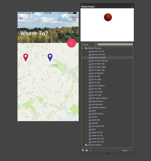
Figure 8-22. The Motion Presets panel gives you 30 stock motion paths
Applying the motion preset automatically inserts a motion tween on the RedPin layer and then adds the relevant property keyframes to reproduce the animation in question
Using the Subselection tool, click the motion path, and then use the Align panel to center the animation vertically on the stage.
As you may have guessed, it’s just as easy to apply the same (or different) motion preset to the other symbol, but we would like to draw your attention to a related feature instead. That related feature is that motion paths can be edited, or created completely from scratch, and then saved to the Motion Presets panel. How? Glad you asked.
Shorten the duration of the RedPin animation by dragging the right edge of the tween span slightly to the left. In our file, we shortened the tween span from 75 frames to 50. Drag the playhead to one or more of the property keyframes and use the Properties panel, Transform panel, or Free Transform tool to alter the symbol’s antics along the existing motion path. Also, the Move the Pin, at the last frame to a street intersection to the left of the pin. Notice how the Pin’s path shows a bounce to that location?
Click the tween span, and in the Motion Presets panel, click the Save selection as preset button (Figure 8-23). You’ll be prompted to give the new preset a name. Enter whatever you like (we used altSmoosh), and click OK. Scroll to the Custom Presets folder to find your preset.
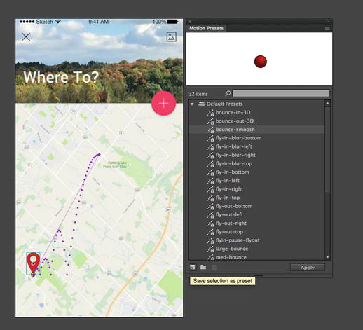
Figure 8-23. Motion paths, whether made from scratch or based on presets, can be saved for later reuse
The other buttons in the Motion Presets panel let you create new folders and delete folders or presets.
Naturally, you could select the BluePin symbol and apply your newly minted custom preset, but there’s another way you can share motion paths.
Right-click (Windows) or Control+click (Mac) RedPin’s tween span and select Copy Motion from the context menu. Now right-click (Windows) or Control+click (Mac) frame 1 of the BluePin layer and select Paste Motion.
Because you used the Align panel to change the position of the original motion path, you’ll need to do the same for the copied path, assuming you want the lunatic and the mascot to fall in sync. It’s easy as pie. Although you could certainly use the Edit Multiple Frames workflow discussed in Chapter 7—that does still work here—you’ve learned in this chapter that motion tweens can be repositioned by way of their motion paths.
Using the Subselection tool, click the BluePin’s motion path to select it. Drag the BluePin’s last position to a street intersection on the right.
Preview the animation. You’ll see that both symbols perform the same movements (see Figure 8-24).
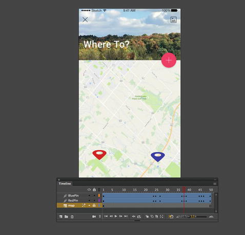
Figure 8-24. Motion paths can be shared even without the Motion Presets panel
That’s impressive enough, but let’s redo the last demonstration in a more dramatic way. These last few steps should drive home the notion that, in Animate CC, motion tweens—specifically, motion paths—are entities that stand on their own, distinct from the symbol.
Select the RedPin symbol at any point along its tween span and delete the symbol.
When you delete the symbol, the tween span remains, along with all its property keyframes. Visually speaking, the only difference in the tween span is that its first frame, usually a black dot, is now an empty white dot.
Click the empty tween span to select it.
Drag a copy of the RedPin symbol from the Library, and drop it somewhere on the stage. Location doesn’t matter—it can even be on the right side of the BluePin symbol on the stage.
Because you selected the tween span first, the symbol will immediately adopt that span’s motion path when you release the mouse to drop the symbol. You can’t do that with a classic tween!
Inverse Kinematics (IK)
In one of the happiest sequences in Disney’s 1940 classic, Pinocchio, the wooden-headed puppet, once freed from the apparatus that formerly helped him move, bursts into song, proudly declaring, “I got no strings on me!” In Animate CC, the authors suspect that you, too, will burst into song—but for the opposite reason—when you see the tools for a feature introduced in Adobe Flash Professional CS4 called inverse kinematics (IK).
What is this academic, vaguely sinister-sounding term? In simple words, IK lets you string up your artwork like a train set, like sausages, or, if you prefer, like a marionette. And when you pull the strings, so to speak, or move one of the connected symbols, your artwork responds like a bona fide action figure. You can use IK to make poseable models and then animate them.
As stated on Wikipedia:
“Inverse kinematics refers to the use of the kinematics equations of a robot to determine the joint parameters that provide a desired position of the end-effector. Specification of the movement of a robot so that its end-effector achieves a desired task is known as motion planning.”
Seriously, this feature is way cool, and we think you’re going to love playing with it. That said, it’s one of the more complicated feature sets in Animate CC. Stringing up your symbols is easy enough. The official terminology calls for creating an armature and populating it with bones, which can then be dragged around. Adobe engineers have made this dead simple.
The tricky part is a question of how. To a certain extent, you’ll find armatures and bones immediately intuitive, but just when you think they make sense, they’ll behave in a way that might just strike you as utterly wrong. You’ll see what we’re talking about in the following exercises, and we’ll show you an approach that should give you what you expect.
It all starts with something called the Bone tool.
When Flash Professional was updated from the CS6 version to CC – it was completely rewritten to modernize the codebase and make the program more powerful than ever. Unfortunately, certain features such as the Bone tool were not rewritten along with the core application. Thus, for a few years, the program did not include this tool. However, Adobe had always stated that features that were left out would be added back in if there was enough of a desire for them. In 2015, we saw Flash Professional receive a revamped and reintegrated Bone tool and inverse kinematics system of animation – and this is now all available in Animate CC as well.
Using the Bone Tool
The Bone tool is your key to the world of poseable armatures in the authoring environment. Using it will give you an inkling of the satisfaction experienced by a certain famous Victor Frankenstein, without anywhere near the hassle he went through or the illegal outings. You won’t be visiting any actual graveyards, for example.
Let’s see how the Bone tool works.
Open the 09_Bones.fla file from the exercise folder for this chapter. You’ll be greeted by a more or less anatomically correct hand, sans flesh. Go ahead and wave! The wrist and hand bones are all part of the same graphic symbol, named “hand” in the Library. The knuckles are also graphic symbols, named by finger and knuckle number—for example, ring1, ring2, and ring3. All of these symbols happen to be on the same layer, but that doesn’t need to be the case.
Select the Bone tool from the Tools panel. It’s the one in Figure 8-25 that looks like a bone, just above or to the left of the Paint Bucket, depending on your Tools panel configuration.
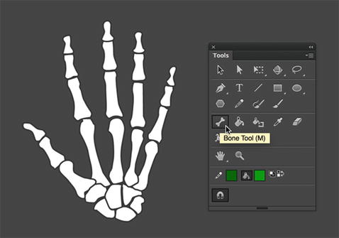
Figure 8-25. The Bone tool lets you connect symbols the way bones are connected in real life
Click over the bottom-center portion of the skeleton’s wrist, and drag toward the bottom of the thumb’s first knuckle, as shown in Figure 8-26. When you release the mouse, you’ll see your very first armature, which includes a single IK bone.
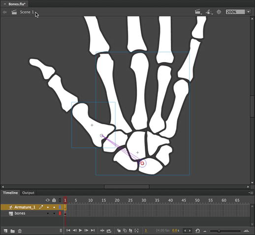
Figure 8-26. Drawing your first bone creates the armature
Bones can only be rigged between graphic symbols, movieclips, or artwork that has been broken apart. Trying to run a bone, for example, from one photo to another will result in an error message telling you, essentially, “Nope you can’t do that!”
Notice the new layer in the Timeline panel, called Armature_1. The layer icon is also noticeably different, resembling a stick figure. That’s your armature, and as you continue to connect your symbols together with IK bones, those symbols will automatically be pulled to this new layer. Just like a motion tween layer, this layer has distinctive properties. For example, you can’t right-click (Windows) or Control+click (Mac) an armature layer to tween it, even though IK poses can be tweened (more on this later in the chapter, in the “Animating IK poses section”). You can’t draw shapes on or drag symbols to an armature layer.
Bones have two ends, and it’s helpful to know their anatomy. The larger end of the bone, where you started to drag, is called the head. The smaller end of the bone, where you released the mouse, is called the tail. The tail is pointing up and to the left in Figure 8-26. A string of connected bones is called an IK chain or a bone chain.
Still with the Bone tool, hover somewhere inside the symbol that represents the first knuckle on the thumb. You don’t need to be exact—just within the symbol’s bounding box. Then click and drag toward the bottom of the second knuckle. You’ll notice that even if you don’t begin the second drag directly over the tail of the first armature bone, Animate CC will automatically snap it into place for you. Release when you’re over the bottom of the second knuckle.
To finish the thumb, hover anywhere inside the second knuckle’s symbol. Click and drag upward to the bottom of the third knuckle. When you release, you’ll have the simple bone rigging shown in Figure 8-27.

Figure 8-27. As you connect symbols with bones, the symbols are pulled to the armature layer
If you’re anything like the authors, you’re just dying to try these bones, so let’s take a quick break and do just that.
Switch to the Selection tool, grab that third knuckle, and give it a shake.
We fully expect you’ll have fun, but all the same, you’ll also see that it’s also pretty easy to arrange the hand into what looks like an orthopedic surgeon’s dream (see Figure 8-28). It may surprise you, for example, that the wrist pivots, and those knuckles are bending into contortions that make even our yoga buddies wince. We’ll fix those issues in just a moment. First, let’s get acquainted with the Bone tool properties.
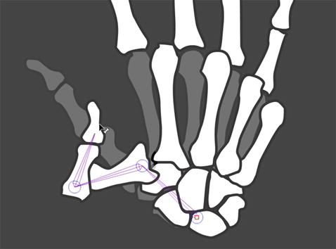
Figure 8-28. Ouch! Bones are easy to connect, but the results aren’t always what you might anticipate
Bone Tool Properties
There are two ways to nudge the Properties panel into showing bone-related properties: by clicking an IK bone on the stage and by clicking the armature itself, which is represented by an armature layer. Let’s start with the armature.
Continuing with the Bones.fla file, click frame 1 of the Armature layer. When you do, the Properties panel updates to show three twirlies:
Ease: In this area, you’ll find a drop-down list for selecting easing from a list of prebuilt choices and a Strength value that lets you specify intensity, just as you saw in the Properties panel for motion tweens. These settings configure easing for the span of an armature layer (you can drag out an armature span to encompass as many frames as you like). Armature layers provide their own tweening capability, which is discussed in the “Animating IK Poses” section and again in the last exercise of this chapter. For now, just note that this is where you can apply easing.
Options: The area gives you something to see even without tweening. The Style drop-down list lets you specify how you want the IK bones to look. You have three choices: Wire (the default), Solid, Line, and None, which are illustrated in Figure 8-29 from left to right. When working with numerous or very small symbols, consider using the Wire or Line styles. Why? Because the Solid view can obscure symbols that appear under the IK bones.
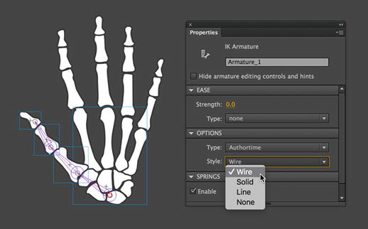
Figure 8-29. Bones can be configured as Wire, Solid, Line, and None
Springs: Allows you to enable or disable springs for the entire armature. Springs are enabled by default.
Change the Type drop-down selection from Authortime to Runtime. You’ll see the warning message shown in Figure 8-30.
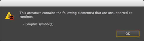
Figure 8-30. Only MovieClip bones can be interactive at runtime
The reason for the warning is that, although bones can be made interactive for the user, Animate CC requires that the boned symbols be movieclips when Type is set to Runtime. Fortunately, this is easy to change, even if there are numerous symbols in play.
Click OK to close the warning dialog box.
Open the Library, and click the first symbol, named hand, to select it. Press and hold the Shift key, and then select the last symbol. Now everything in your Library is selected.
Right-click (Windows) or Control+click (Mac) any one of the symbols and choose Properties from the context menu.
What you get is a feature introduced way back in Flash Professional CS4, which is an incredible time-saver. The Symbol Properties dialog box opens—not just for the symbol you clicked, but for all selected symbols.
In the Symbol Properties dialog box, place a check mark in the Type property, and change the drop-down choice to Movie Clip, as shown in Figure 8-31. Then click OK.
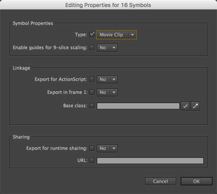
Figure 8-31. Animate CC lets you change multiple symbol properties at once in the Library
All of your Library’s graphic symbols become movieclips simultaneously. This used to take a separate visit to each asset. However, you still need to let the stage know what you’ve done.
Click the stage to select it. Select Edit ➤ Select All. In one swoop, you just selected all your symbol instances on the stage.
Click any one of the symbol instances to update the Properties panel, and then select MovieClip from the drop-down list at the top of the Properties panel.
Click frame 1 of the Armature layer and change the Type drop-down selection to Runtime.
Test the movie and wiggle those thumb knuckles inside Flash Player. Pretty neat!
Close the SWF and click one of the IK bones to update the Properties panel.
Runtime Armatures in HTML5 Canvas
As you’ve seen, in order to manipulate IK at runtime, your armature must be composed of MovieClip symbol instances. There is another restriction to consider when dealing with armatures—target document type, as shown in Figure 8-32.
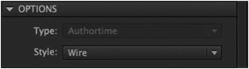
Figure 8-32. When targeting HTML5 Canvas, you cannot select Runtime as an Armature Type
12. With the properties updated, double-click one of the bones on the stage (not the symbol instance) and in the Properties panel you now see bone-specific properties. Let’s go over those:
Position X, Y, Length, and Angle: These are read-only properties, which means you can look, but don’t touch. Thankfully, the names are self-explanatory.
Speed: Think of this as friction, or how much “give” the selected bone has in the armature. A higher number means faster movement, and your range is 0 (no movement) to 200 (fast movement). You can also select the Pin check box here to pin the tail of the selected bone to the stage.
Joint: Rotation: Here, you have the following choices:
Enable: Selecting this check box allows the bone to pivot around its head. In contrast, deselecting it means the bone won’t act like a hinge.
Constrain, Min, and Max: Selecting Constrain activates the Min and Max hot text values, which allow you to determine how wide an arc your hinge can pivot on.
Joint: X and Y Translation: The choices for this property are as follows:
Enable: Selecting this check box allows the bone to effectively pop in and out of its socket, in the X- or Y-axis.
Constrain, Min, and Max: Selecting Constrain activates the Min and Max hot text values, which allow you to determine how far the bone can move.
Spring: This property integrates dynamic physics into the Bones IK system. The two properties allow easier creation of physics-enhanced animation.
Strength: Think of a car spring and a Slinky. The car spring is rigid, whereas the Slinky is totally bendable. The Strength property stiffens a spring. If the Slinky has a value of 0, then a car spring has a value of 100.
Damping: The rate of decay of the spring effect. Higher values cause the springiness to diminish more quickly. A value of 0 causes the springiness to remain at its full strength throughout the frames of the pose layer
Of the properties available, Rotation , Translation , and Spring will give you the biggest bang for your buck. Let’s see how easy it is to fix that misshapen hand! While we’re at it, you’ll learn some helpful subtleties on manipulating the symbols in an armature.
Constraining Joint Rotation
IK bone rigs are as much an art as a science. The science facet derives from the Properties panel, which gives you have some configuration settings. The art facet depends on your sense of the appropriate range of motion for a given armature. Let’s jump in:
Continuing with the Bones.fla file, use the Selection tool to drag the hand itself—not any of the fingers or the thumb—and carefully pivot the hand so that it realigns again under the fingers.
Select the first IK bone (the one closest to the wrist), and deselect the Enable check box in Properties panel‘s Joint: Rotation area.
Drag the thumb’s third knuckle again, and note that the wrist no longer moves.
If you ever change your mind, just reselect the first IK bone, and put a check mark back in the Enable property. Now let’s make sure the thumb doesn’t look so double-jointed.
Select the second IK bone and, in the Properties panel, enable the Constrain check box in the Joint: Rotation area, as shown in Figure 8-33.
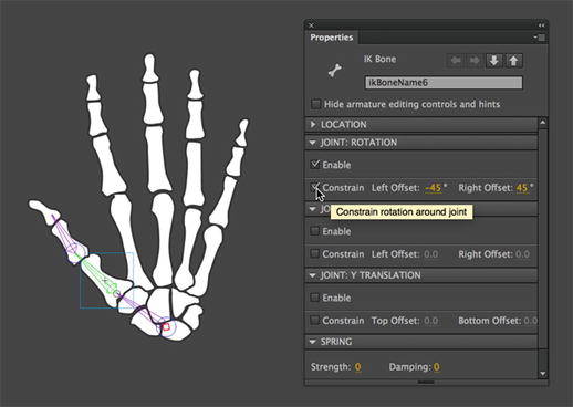
Figure 8-33. The Constraint check box lets you constrain a joint’s range of motion
Choosing Constrain adds a new component to the IK bone, which you can see in Figure 8-34. Suddenly, the bone’s head sprouts a wedge shape, with a line in the middle that separates the wedge into two pie pieces. The line has a square handle on its outside end. (If you’re in a Robin Hood mood, it may look like a bow and arrow.) This wedge represents the joint’s range of movement. By default, you get a 90-degree sweep.
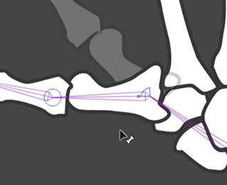
Figure 8-34. Select Constrain in the Joint: Rotation area of the Properties panel , and joints sprout a range-of-movement icon
Drag the third knuckle downward. The line with the square handle moves counterclockwise until it rests against that side of the wedge. Drag the knuckle up, and the handle moves to the other side—clockwise—until it meets the opposite side of the wedge.
Adjusting this range of movement is easy. The workflow we prefer is to pivot the IK bone into position first and then scrub the Min or Max hot text as necessary to meet that position.
Drag the third knuckle upward until the thumb moves as far in that direction as you like. If you need more room, select first knuckle’s IK bone, and scrub the Max value toward the right to increase its value. Readjust the thumb, and when you like how it sits, scrub the Max value toward the left again to bring the edge of the wedge toward the square-handled line.
Drag the third knuckle all the way down, and repeat this process for the other extreme. You’ll notice that the first knuckle appears above the bones of the wrist. That may or may not be what you want. If you want to send the knuckle behind the wrist, use the Selection tool to select that knuckle’s symbol and select Modify ➤ Arrange ➤ Send to Back. The first knuckle is done. You can now move onto the second, which isn’t any harder to manage.
Add a Joint: Rotation constraint to the second knuckle and configure the Min/Max values in whatever way suits you.
As you move the skeleton bones around, you can use the Shift key to temporarily change the way the IK bones respond. For example, drag the third knuckle up and down, and then hold down Shift and drag again. When Shift is pressed, only the third knuckle moves. This works with any other bone. Drag the second knuckle with and without Shift to see what we mean.
While you’re at it, experiment with the Ctrl (Windows) or Cmd (Mac) key as well. If you ever want to reposition a symbol without having to redo an IK bone from scratch, hold down Ctrl (Windows) or Cmd (Mac) while you drag. This temporarily releases the dragged symbol from its IK chain. When you release the key, the IK bones are reapplied.
The third knuckle is the interesting one, because although it’s attached to an IK bone, it’s only associated with that bone’s tail. This means you can’t constrain its rotation. (Give it a try!) So, what to do? Since we’re dealing with so many kinds of bones, we think it’s fitting that the answer relies on the presence of a ghost—not a real ghost, of course, but a stand-in “ghost” movieclip.
In the Timeline panel, select the non-armature layer (the one labeled bones).
Use the Oval tool to draw a small circle—say, 20 pixels by 20 pixels—no stroke, and color doesn’t matter.
Convert that circle to a MovieClip. Name the symbol Ghost and position it just past the thumb’s third knuckle.
Using the Bone tool, add a fourth IK bone between the third knuckle and the ghost handle movieclip, as shown in Figure 8-35.
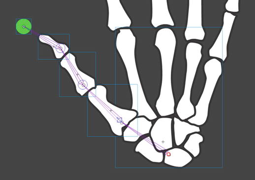
Figure 8-35. Use a stand-in movieclip to let you constrain the previously end-of-the-line IK bone
Select the newest IK bone and constrain its Joint: Rotation property.
Save your file.
Sure, the ghost movieclip may look a little silly, but its presence allows you to configure your IK bones from start to finish.
Here’s the best part: whenever you need another stand-in IK bone, make sure to keep reusing that same Ghost MovieClip . Why? Because when you’re ready to publish the project, all you have to do is open that symbol in the Library and change its fill color to 0% Alpha. Just like that, your extra handles become invisible, and they still do their job.
Deleting Bones
We showed you how to create IK bones, but you’ll also want to know how to delete them. It couldn’t be easier:
After saving your Bones.fla file, use the Selection tool to select the fourth IK bone from the previous exercise. Press the Delete key. Badda bing, badda boom…the bone is gone.
Skip the third IK bone and select the second one. Press the Delete key.
This time, both the second and third bones disappear. This tells you that deleting an IK bone automatically deletes any other bones attached to its tail.
Right-click (Windows) or Control+click (Mac) frame 1 in the Armature layer and select Remove Armature from the context menu.
As expected, the last IK bone disappears. If you had made this selection in step 1, all of the IK bones would have disappeared from the start.
Select File ➤ Revert and then click the Revert button in the alert box to undo all the deletions.
Putting Some “Spring” in Your Bones
In addition to general IK properties such as Rotation and Translation, there is a Spring option for bones. Adobe calls it a “physics engine for Inverse Kinematics” and, regardless of what you call it, we think it’s a pretty neat way of bending stuff in an animation.
You may notice in this exercise that we are using IK on shapes and not symbol instances. The IK tooling can be used on either Animate CC object type!
Okay, let’s take a look:
Open the 10_Springs.fla file in your exercise folder. When it opens, you will see two trees on the stage, and if you scrub across the timeline, you will see them bend in a gust of strong wind.
Springiness works best when the object containing the bones is put into motion. This is done using poses, which we will get into later in this chapter.
Click the tree on the left, and click the bone at the bottom to select it.
Open the Properties panel, and you will notice the bone has a Strength value of 100 and a Damping value of 5. Strength is the stiffness of the spring (see Figure 8-36). Higher values create a stiffer spring effect. Damping is the rate of decay of the spring effect. Higher values cause the springiness to diminish more quickly. A value of 0 causes the springiness to remain at its full strength throughout the frames of the pose layer.
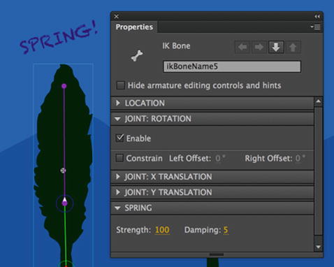
Figure 8-36. Adding spring to a bone using the Strength and Damping properties
Now that you know what the values mean, scrub across the timeline to the first keyframe and compare the shapes of the trees. The tree on the right does not have springiness applied to it. As shown in Figure 8-37, the tree that has been “stiffened” looks a lot more natural than its counterpart on the right which has had springiness disabled.
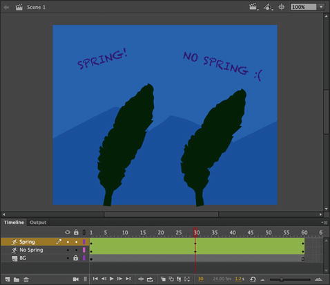
Figure 8-37. Springs, used in the tree on the left, add realism to objects in motion
There is something else you need to know: Spring properties are applied to bones. Springiness is applied to layers. If you click any frame of the NoSpring layer and open the Properties panel, you will see that the Enable check box for springs is deselected.
Applying Joint Translation
Another way to control the movement of joints is called joint translation—generally meaning a change in position or movement. This affects movement of an IK bone along its X- or Y-axis (or both). To illustrate, we’ll leave our skeleton at the chiropractors for a while and turn our attention to a vampire.
“Sava Savanović was said to have lived in an old watermill on the Rogačica river, at Zarožje village in the municipality of Bajina Bašta . It was said that he killed and drank the blood of the millers when they came to mill their grains.” – Wikipedia
It was in November of 2012 that the authorities of the Serbian village of Zarozje issued a warning to the world after the vampire’s mill (the place he would reside in) collapsed. The local mayor even stated “People are worried, everybody knows the legend of this vampire and the thought that he is now homeless and looking for somewhere else and possibly other victims is terrifying people. We are all frightened.” Truly frightening. Let’s build Sava a new mill.
Open the Mill.fla file from the Chapter 8 exercise folder. The symbols are already in place for you and there is much additional artwork to help attract Sava back to his refuge.
In Figure 8-38, we’ve labeled the mill wheel assembly’s anatomy to assist you in the next steps, so you can focus your attention entirely on the IK rigging. You’re going to connect three horizontal symbols from left to right. Ignore the actual wheel for the time being.
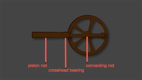
Figure 8-38. The movement of this mill wheel will include joint translation
Select the Bone tool and then add a bone that starts on the left side of the piston rod symbol and ends on the crosshead bearing symbol (the center symbol).
Add another bone from the crosshead bearing symbol to the right side of the connecting rod symbol, as shown in Figure 8-39. This is no different from the bone rigging you did for the knuckles.
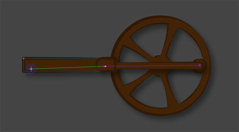
Figure 8-39. Two bones connect three symbols
Joint translation doesn’t require ActionScript, but we’re going to use some programming to demonstrate it in this particular case. Because we’ll be using ActionScript, let’s give the bones and armature meaningful instance names.
Using the Selection tool, select the bone on the right, and use the Properties panel to give it the instance name connectingRod, as shown in Figure 8-40.
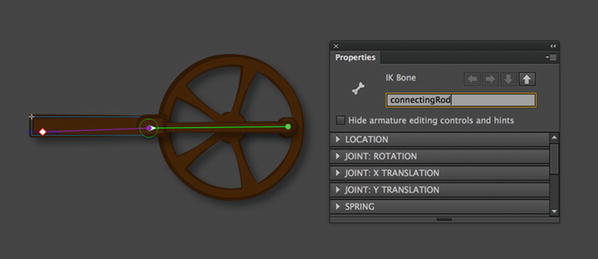
Figure 8-40. Bones and armatures support instance names, just like movieclip symbols
Pay close attention to the Properties panel when making your selections. It’s easy to accidentally click the symbol to which a bone is applied, rather than the bone itself. In this context, the symbol is listed as an IK Node in the Properties panel. If you select an IK node, this exercise won’t work properly. Figure 8-41 shows the correct selection of a bone, which displays IK Bone in the Properties panel.
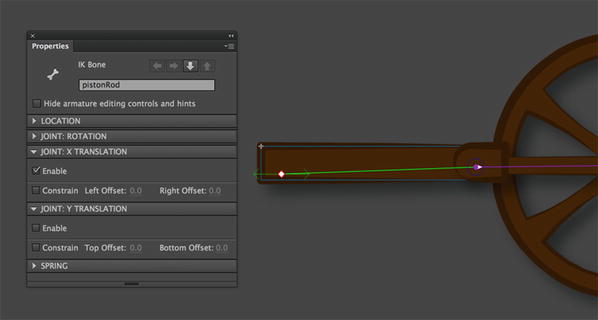
Figure 8-41. Joint translation is indicated by a double-headed arrow along the relevant axis
Select the other bone and give it the instance name pistonRod.
Select the armature itself by clicking frame 1 of its layer in the Timeline panel. Use the Properties panel to give the armature the instance name engine. The armature’s layer name will update to the same name.
Now it’s time for the joint translation, but first, let’s keep this bone from rotating. It’s possible for bones to translate and rotate, but that isn’t what we want here. Our aim is to let the piston rod slide left and right when the armature moves.
Select the pistonRod bone and use the Properties panel to disable its rotation (that is, deselect the Enable check box in the Joint: Rotation area).
To achieve the left-and-right motion, select the Enable check box in the Joint: X Translation area. The bone’s head gets a horizontal double-headed arrow, as shown in Figure 8-41.
You could optionally constrain this translation by selecting the Constrain check box and configuring Min and Max values, just as with joint rotation, but that isn’t necessary here. Note, too, that you could optionally translate (and constrain) along the y-axis, but we’ll also omit that step.
Time to get Sava’s wheel moving!
Click frame 1 of the armature’s layer (engine) to select the armature. In the Options area of the Properties panel and change the Type drop-down selection to Runtime. Now this rigging is ready for ActionScript.
Select frame 1 of the Actions layer and open the Actions panel. Type the following ActionScript:
import fl.ik.*;var pt:Point = new Point();var arm:IKArmature = IKManager.getArmatureByName("engine");var bone:IKBone = arm.getBoneByName("connectingRod");var tail:IKJoint = bone.tailJoint;var pos:Point = tail.position;var ik:IKMover = new IKMover(tail, pos);The first line imports all the classes in the fl.ik package, which includes classes necessary for identifying and manipulating armatures created in the authoring tool. The next line declares and instantiates a variable, pt, set to an instance of the Point class. (The Point class doesn’t reside in the fl.ik package, but in just a moment, you’ll see that something called the IKMover class needs a Point instance.)
From the third line on, the code unfolds like the lyrics in that old catchy tune, “Dry Bones” (“the knee bone’s connected to the…thi-i-igh bone”). How so? A variable, arm, is declared and set to an instance of the IKArmature class. This variable takes its value from a method of the IKManager class, which connects it to the armature whose instance name is engine.
After that, a bone variable—an instance of the IKBone class—is connected to the bone whose instance name is connectingRod. Then a tail variable (IKJoint class) is connected to the tailJoint property of the bone instance. Finally, a new Point instance (pos) is connected to a pair of coordinates from the position property of the tail instance.
The tail and pos variables are passed as parameters to a new instance of the IKMover class, which is stored in the variable ik. That ik variable allows you to move the armature with code.
Add the following new ActionScript after the existing code:
wheel.addEventListener(Event.ENTER_FRAME, spin);function spin(evt:Event):void {wheel.rotation += 5;pt.x = wheel.crank.x;pt.y = wheel.crank.y;pt = wheel.localToGlobal(pt);ik.moveTo(pt);}The basic premise here is something you’ve already seen in other chapters: a custom function, spin(), is associated with the Event.ENTER_FRAME event of an object with the instance name wheel. In this case, wheel is the instance name of the wheel-shaped movieclip symbol. (We’ve already configured the instance name for you in the sample file, and the wheel symbol contains another movieclip inside it with the instance name crank.)
So, what’s going on in this event handler? First, the MovieClip.rotation property of the wheel instance is incremented by five. That gets the wheel rolling continuously. After that, it’s just a matter of updating the pt variable declared earlier. Being an instance of the Point class, the pt variable has x and y properties, which are set to the crank movieclip’s x and y properties, respectively. Because crank resides inside wheel, the object path to the desired x property is wheel.crank.x. The same goes for y.
This updates pt’s properties to the current position of crank, but that isn’t quite enough. From the wheel symbol’s point of view, crank never actually moves—it’s wheel that does the rotating!—so the coordinates need to be considered from the point of view of the stage. That’s what the second-to-last line does by invoking the DisplayObject.localToGlobal() method on the wheel instance. In plain English, it tells pt to reset itself in from crank‘s local coordinates inside wheel to the crank‘s global coordinates shared by all objects on the stage.
Finally, pt is passed as a parameter to the IKMover instance represented by the ik variable.
Test your movie so far to see the result.
It’s close to being correct, and the pistonRod bone does perform its horizontal joint translation, but if you look carefully, you’ll notice that the armature occasionally “slips” from the crank movieclip. That’s easy to fix, and it’s nothing more than a matter of priorities.
The armature isn’t updating as quickly as the wheel turns, so let’s fix that by tweaking the number of calculations it has to make.
Use the Actions panel to insert the following two lines after the ik variable declaration and before the event listener (the new code is shown in bold):
...var ik:IKMover = new IKMover(tail, pos);ik.limitByIteration = false;ik.iterationLimit = 5;wheel.addEventListener(Event.ENTER_FRAME, spin);function spin(evt:Event):void {...Test the movie again. As you can see in Figure 8-42, everything should run fine.
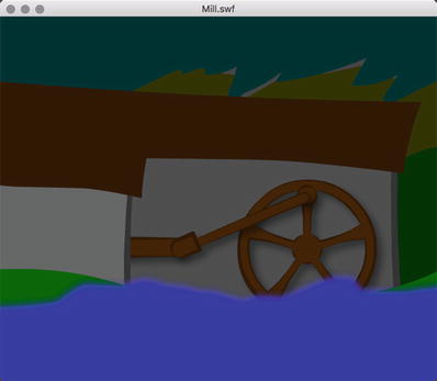
Figure 8-42. The completed mill—you’ve saved Serbia from the vampire’s wrath!
We’ve used ActionScript to wire up the code for this example. What if you needed to use JavaScript instead? Sorry, you’re out of luck and Sava has you for an early breakfast. JavaScript and CreateJS simply do not allow the sort of control over armatures that ActionScript does so you must be targeting either Flash Player or AIR for the above to work correctly. Of course, you can always perform the same sort of animation without code when targeting HTML5 Canvas. It’s a matter of choice and approach.
A Note About Bone Preferences
Let’s return to our friendly skeleton hand. We mentioned earlier in this chapter that IK poses can be animated, even without the use of a motion tween layer. You’ll see how in the next section. First, it’s time for a quick field trip.
Open the 11_BonesRigged.fla file in this chapter’s exercise folder. You’ll see the fingers and thumb pointing upward, and the thumb has a ghost handle.
Use the Selection tool or the Free Transform tool to click the first knuckle of the pointer finger. As Figure 8-43 shows, the symbol’s transformation point (the small white circle) is dead center.
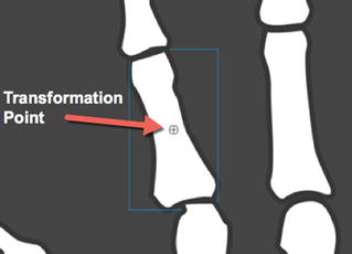
Figure 8-43. This symbol’s transformation point is horizontally and vertically centered
Noting the transformation point, select Edit (Animate CC) ➤ Preferences, and click the Drawing choice in the Category area. Find the IK Bone tool: Auto Set Transformation Point check box and deselect it, as shown in Figure 8-44. Click OK to close the Preferences dialog box.
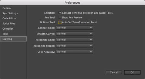
Figure 8-44. The Auto Set Transformation Point setting affects how bones are applied to symbols
Using the Bone tool, hover over the hand symbol, and then click and drag a new IK bone toward the first knuckle of the pointer finger. As you do, notice that the tail of the IK bone snaps to the transformation point of the first knuckle. Note, also, that the armature is perfectly capable of handling more than one chain of bones.
Repeat this process to rig up the remaining knuckles of the pointer finger.
Using the Selection tool, grab the third knuckle and give the finger a wiggle. As shown in Figure 8-45, the pivots occur on the transformation points, which just doesn’t work for this scenario. We want the knuckles to line up end to end.
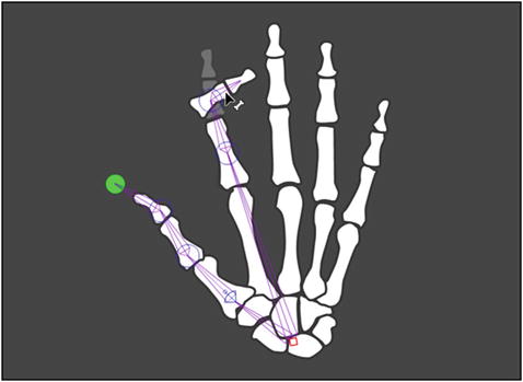
Figure 8-45. If you want, IK bones can snap to a symbol’s transformation point
Return to the Preferences dialog box and reselect the IK Bone tool check box.
Select File ➤ Revert and then click the Revert button to roll the file back to its original state.
We brought up the IK Bone tool preference setting because it’s hard to spot unless you happen to be poring through the Preferences dialog box. We chose a silly example because silly visuals tend to stick.
By leaving the Auto Set Transformation Point check box selected in the Preferences dialog box’s Drawing section, you’re telling Flash to move a symbol’s transformation point for you automatically. If you prefer to maintain that control on your own, deselect that check box, and then use the Free Transform tool to make your symbol selections. When selected with the Free Transform tool, a symbol lets you move its transformation point with an effortless click-and-drag operation. If the symbol already belongs to an IK chain, any heads or tails connected to it will reposition themselves to the new location of the symbol’s transformation point.
Animating IK Poses
As you saw earlier with the springs example, to get those trees to bend in the wind, we needed to animate the IK poses. In this section, we show you how to do that but rather than bend trees, let’s slip on our hard hats and visit a construction site.
Open the 12_Poses.fla file in your exercise folder. You will see we have placed a Steam Shovel on the stage. The image started life as a multilayer Photoshop image imported into Animate CC. Each layer of the Photoshop image was placed in a graphic symbol, and each symbol has its own layer on the main timeline.
Select the Magnifying Glass tool and zoom in on the machine. You are going to need a closer view of the pieces to place the bones.
Select the Bone tool and draw a bone from the back of the MainArm symbol to the top joint of the ShovelArm symbol. Keep in mind that Bones only link symbols to each other. Bones within a symbol will kick out an error message. In this case, run the bone between the MainArm and ShovelArm symbols, as shown in Figure 8-46.
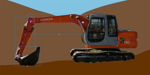
Figure 8-46. The bones used in the animation are in place
Draw another bone from the top of the ShovelArm symbol to the joint where the shovel is attached to the ShovelArm. The three symbols have been moved from their respective layers to the armature layer.
Right-click (Windows) or Control+click (Mac) frame 70 of the Cab layer and select Insert Frame. The Cab symbol now spans 70 frames. Lock the Cab layer.
We are going to start the animation by establishing its finish position. Right-click (Windows) or Control+click (Mac) frame 70 of the armature layer, and, as shown in Figure 8-47, select Insert Pose from the context menu.
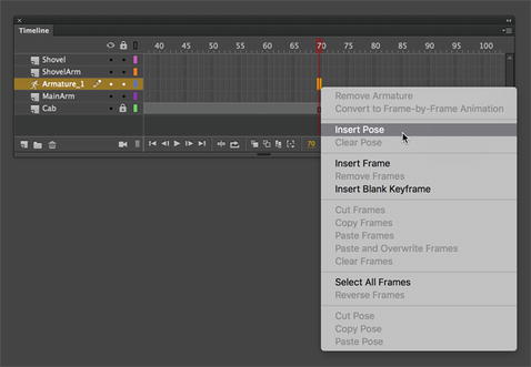
Figure 8-47. Poses are added through the context menu
That green strip across the armature layer tells you that you have created a pose layer. Pose layers are quite different from motion layers. They can only be created by adding a pose at a frame and they only work with armature layers. The little keyframe icon in the pose layer tells you where the poses are located.
Scrub back to frame 1. Switch to the Selection tool, and move the arms and the shovel to the position shown in Figure 8-48. If you scrub across the timeline the two arms and the shovel lower to the ground. This tells you that poses in an armature layer can be tweened only in the armature layer.
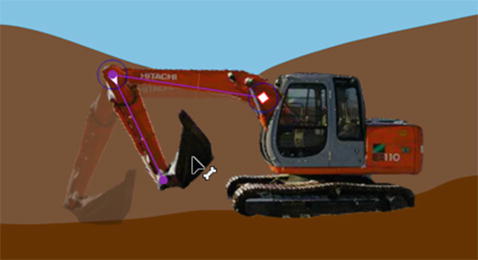
Figure 8-48. Use the Selection tool to change a pose
Move the playhead to frame 15. Switch to the Selection tool, and extend the shovel arms. What you need to know about this is that by changing the positions of the bones in an armature layer, a keyframe is automatically added. There is no need to insert a pose. This may sound rather familiar because this is exactly what happens when you change the properties of an object in a motion layer.
At this point you can continue moving through the timeline and having the machine scoop up and dump some dirt however you wish. When finished, go ahead and close this example and don’t save the changes.
Using the Bind Tool
We expect that IK has sparked the creative center of your brain enough to keep you happily busy for weeks. Believe it or not, you still have one more tool to see. The team at Adobe has made IK available not only to symbols but also to shapes! You’ll be using the Bone tool for this exercise, but the Bind tool will make an appearance as an important sidekick. The best way to describe IK for shapes is to consider it a super-advanced evolution of shape tweens in combination with the shape hinting discussed in Chapter 7. Let’s jump right in.
When it comes to IK, the distortion to be controlled is in both the stroke and fill areas of a shape. Depending on the configuration of an IK shape, you may find that the stroke of the shape does not distort in a pleasing way or joints move around when moving the armature. This is where the Bind tool comes into play.
By default, the control points of a shape are connected to the bone that is nearest to them. The Bind tool allows you to edit the connections between individual bones and the shape control points. The upshot is you control how the stroke distorts when each bone moves.
Before we start, it might not be a bad idea to simply take a look at what effect “binding” has on a drawing. This way, you can see in a rather dramatic fashion what it does and learn what to look for.
Open the 13_BadBind.fla file in your exercise folder. When it opens, you will see a girl resting her arm.
Click the girl’s left arm to see the bones.
Switch to the Selection tool and move the arm. You will notice two things, as shown in Figure 8-49. First, the elbow moves from the bottom of the stage and some rather disturbing distortions occur around the elbow joint.
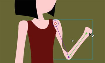
Figure 8-49. Moving a bone in a shape causes distortions and artificial movement
Open the GoodBind.fla file in your exercise folder and give the arm a wiggle. As you can see the distortions are not nearly as severe.
Now that you have seen how binding can affect an armature, let’s get to work and start learning how to use the Bind tool.
Open the 14_Worm.fla file in the exercise folder for this chapter and say hello to a smiling worm, as shown in Figure 8-50. (The correlation between a worm, bones, steam shovels, and graveyards is purely coincidental, we assure you.) The Library for this FLA is empty, because the worm is nothing more than a handful of shapes.
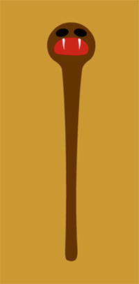
Figure 8-50. IK for shapes is brought to you by a worm
Assuming you want to drag the worm around by its head, you’ll want to draw the bones of your armature from the opposite side of the worm. Select the Bone tool and starting from the bottom of the shape, drag a small IK bone upward.
With that first bone in place, hover over the tail of the IK bone. When the tiny white bone icon inside the mouse cursor turns to black, you’ll know you’ve hit the right spot. Click and drag upward to add another bone.
In this manner, keep adding small IK bones until you reach the top of the worm (see Figure 8-51).
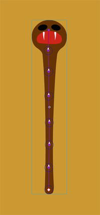
Figure 8-51. IK bones can easily be applied to shapes
Before you give the worm a wiggle, switch to the Bind tool, and click the bottom-most IK bone.
This is where it gets interesting. Using the Bind tool, marquee the bottom several bones in the tail. Now you’re ready for action.
Using the Bind tool is a bit like using the Subselection tool in that it reveals a shape’s anchor points. In Figure 8-52, you can see anchor points represented in three different ways. At the top of the figure, they look like the sort you’ve seen in previous chapters—just small squares. At the bottom, they’re considerably larger and thicker and appear in the form of triangles as well as squares.
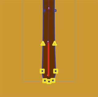
Figure 8-52. The Bind tool lets you manipulate anchor points
When you select an IK bone with the Bind tool, Animate CC shows you which of the shape’s anchor points are associated with that particular bone. Squares indicate an association with a single bone; triangles indicate an association with many bones.
In this case, the bottom four anchor points—the heavy squares—are associated with the bottom-most bone only. The upper two anchor points—the heavy triangles—are associated with the bottom-most bone and with the bone immediately above it. The triangle anchor points are affected when either of their associated bones moves.
Click any of the other IK bones in this armature, and you’ll see that Animate CC has done a great job of automatically deciding which associations to make. This won’t always be the case. Thankfully, you can override these decisions.
Hold down the Ctrl (Windows) or Cmd (Mac) key, and click one of the bottom four heavy squares. This makes it look like a normal anchor point (smaller and not bold). Still holding Ctrl (Windows) or Cmd (Mac), click one of the heavy triangles, which also becomes a normal anchor point.
Select the next IK bone, and you’ll see that the triangle anchor is back. but now it’s a heavy square. That makes sense: before step 6, this anchor was associated with two bones (triangle), but now it’s associated with only this one (square).
Select the bottom-most bone again, and, without holding down Ctrl (Windows) or Cmd (Mac), click the anchor point that was previously a heavy square. Drag it toward the bone (see Figure 8-53) and release. That anchor point is now reassociated with the bone.
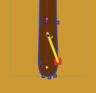
Figure 8-53. Click and drag an anchor point to associate it with a bone
Click another bone, and then click this one again. You’ll see the heavy square as it originally was, along with its companions.
To reassociate the formerly triangle anchor point, use the Bind tool to select the appropriate anchor, and then press and hold Ctrl (Windows) or Cmd (Mac) while you drag it to the bottom-most bone. As you do, you’ll see an association line in the upper bone as well as the diagonal association line created by your dragging (see Figure 8-54).
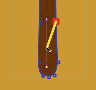
Figure 8-54. Press Ctrl (Windows) or Cmd (Mac) while dragging to associate an anchor point with more than one bone
Save the file. (You’re going to continue with it in the next exercise.)
Use the Bind tool to fine-tune your shape armatures, just as you would use shape hints to fine-tune a shape tween. Any anchor points not associated with an IK bone are ignored when the armature is manipulated.
Your Turn: Animate a Fully Rigged IK model
We figure you appreciate worms, bending trees, steam shovels, and skeleton hands as much as the next designer (and so do we!). But surely, your thoughts have already wandered toward more complex implementations. We suspect you’re wondering if the IK tools are useful for more than a few fingers. What about a whole body? The answer to these questions is yes, and you’re about to find out firsthand. In this final exercise of the chapter, you’ll expand on what you learned in previous sections by rigging up a character with arms and legs and then animating it. Let’s do it.
Open the 15_Penelope.fla file from the exercise folder. You’ll see an assembled collection of symbols in human form. Let’s name her Penelope (see Figure 8-55).
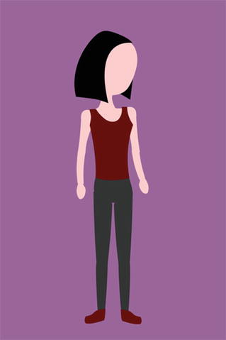
Figure 8-55. Let’s bring Penelope to life!
Select Edit (Animate CC) ➤ Preferences and click the Drawing choice in the Category area. Deselect the IK Bone tool: Auto Set Transformation Point check box. Click OK to confirm the changes. As described in the “A Note About Bone Preferences” section earlier, this means you’ll be the one deciding where to place your bone heads and tails, and you’ll adjust them afterward.
Select the Oval tool and, in the Penelope layer, draw a small circle about 22 pixels × 22 pixels near one of the character’s hands. Select the shape and convert it to a MovieClip symbol named Ghost. This is going to be your “ghost handle,” which lets you constrain the hands, feet, and head.
Drag additional instances of the handle symbol from the Library to the stage, positioning them near the Penelope’s other hand, her feet, and her head, as shown in Figure 8-56. In this exercise, Penelope’s chest will act as the starting point for every new chain of bones, just as the skeleton’s palm did in earlier exercises.
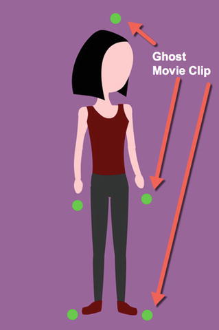
Figure 8-56. Make sure to include extra symbols to allow for rotation constraints
Select the Bone tool and then click and drag a bone from the torso symbol to the pelvis symbol.
Now drag a bone from the pelvis to one of the legs. Be sure to release the bone’s tail low enough on the upper leg that it clears the bounding box of the torso (see the bounding box in Figure 8-57, and note how the bone tail falls below it). Even though this puts the bone tail lower than it should on the leg symbol—effectively moving the “hip” into the thigh—you’ll be able to readjust it in just a moment.
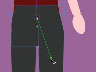
Figure 8-57. Make sure the bone’s tail clears the bounding box of the pelvis symbol
The fact these symbols overlap is part of the reason we had you deselect Auto Set Transformation Point in step 2. Although not always a problem, in this case, the obscured symbol rotation points make it harder for Animate CC to decide on its own where new chains of bones should begin.
Just as you did earlier for the knuckles, continue adding a new bone that connects the upper leg to the lower leg, the lower leg to the foot, and finally the foot to the foot’s ghost handle. Feel free to zoom the stage—particularly for the foot!—if necessary.
Select the Free Transform tool and then click the stage to deselect the armature itself.
Click each symbol in turn, from the ghost handle back up to the torso, and adjust the transformation point so that it sits over the symbol’s registration point. To do this, click the white circle (transformation point), drag it to the small plus sign (registration point), and then release. Selecting Snap to Objects in the Tools panel will make this task easier for you.
After you’ve adjusted the transformation point for each boned symbol, select the Bone tool again, and click the head of the torso’s existing bone to begin a new chain of bones down the other leg. Follow this with a repeat of the Free Transform tool adjustments of the relevant symbols’ transformation points.
Obviously, the arms need the same treatment, as does the head. Starting from the same gathering of torso bones each time, use the Bone tool to create new bone chains from the torso to upper arm, lower arm, hand, to ghost handle on both sides, and then from torso to head to ghost handle at the top of the character. When you’re finished, revisit all relevant symbols with the Free Transform tool to reposition transformation points over their corresponding registration points. Your armature should look like the one shown in Figure 8-58.

Figure 8-58. A complete IK rig
Go ahead and adjust the Alpha property value to 0 in the Properties panel Color Effect area with each Ghost instance selected to render them all invisible. You can still select them for various adjustments, even if not they aren’t visible!
At this point, Penelope is nearly ready for her stretches. First, we need a few rotation constraints.
Using the Selection tool, click any of the torso bones and deselect the Enabled option in the Joint: Rotation area of the Properties panel. Because all the torso bones share the same head, this action will disable rotation for the whole body.
Add rotation constraints to the remaining bones according to your preferences. For example, select the lower leg’s bone, and in the Properties panel, select the Constrain option and adjust the Min and Max values to keep the knee from bending backward.
When you’re finished, the Timeline‘s original Penelope layer will have long since been emptied, because every symbol was moved to the automatically created armature layer as it was associated with a bone.
Create a new layer named Poses and move it below the layer containing your armature.
Select File ➤ Import ➤ Import to Stage and import the jumping.jpg file in this chapter’s exercise folder. This JPG features a number of hand-drawn poses you can use as guides to manipulate the armature. Position the imported JPG slightly to the right, so that it appears behind Penelope, and then lock the armature layer.
Select the imported image and adjust its size until the initial drawn pose matches the height of Penelope, as shown in Figure 8-59. You will use this as a guide to position the armature.
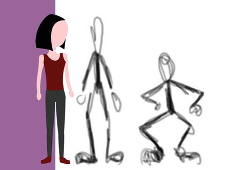
Figure 8-59. Resize the hand-drawn guides to match Penelope, and you’re set
Penelope’s jump should take about one second. Because the movie’s frame rate is 24 fps, that means 24 frames is fine.
Hover near the right edge of the of the armature’s single frame until the icon turns into a double-headed arrow. Drag out the armature span until it reaches frame 24.
Right-click (Windows) or Control+click (Mac) the poses layer at frame 24, and select Insert Frame from the context menu. This matches up the JPG to the time span of the armature layer.
We’re about to cut you loose, so here’s the basic gist of what you’ll repeat until the sequence is finished:
Unlock the poses layer and slide the JPG to the left in order to position the next pose under the armature. Once the JPG is moved, lock the poses layer again.
Drag the playhead six frames to the right (one-fourth of the armature span, because there are four poses after the first drawing).
Use the Selection tool to manipulate the character’s body parts so they match the hand-drawn pose.
Here are two important tips:
Depending on how you might have constrained your joints, you may not be able to match the drawing perfectly. Treat the drawings as rough guides. You may have noticed, for example, that our elbows don’t match the pose at all—they’re bent in the opposite direction! Just have fun with it.
You will often need to move the whole armature at once. To accomplish this, hold down the Ctrl (Windows) or Cmd (Mac) key, and click the current frame of the armature layer. Doing so simultaneously selects all the armature’s symbols in the chosen frame. At this point, slowly tap the keyboard’s arrow keys to move the armature. If you hold down Shift while pressing the arrow keys, you can move in 10-pixel increments, which makes it go faster.
After you’ve finished posing the armature at frames 6, 12, 18, and 24, right-click (Windows) or Control+click (Mac) the poses layer and convert it to a guide layer. This will keep it from showing when you publish the project. (Alternatively, you could hide the poses layer and configure your preferences to omit hidden layers from the published project—or simply delete the poses layer.)
Save your file and test the movie.
What You Have Learned
In this chapter, you learned the following:
How to use the Motion Editor
That even though the new tweening model is intended for the Motion Editor, the Timeline continues to be useful for motion tweens
How to use and configure advanced easing graphs and how to create your own
How to navigate property keyframes in the Motion Editor and Timeline
How to change the duration of a tween span
How to manipulate and reuse motion paths, with or without the Motion Presets
How IK works in Animate CC
How to use the Bone and Bind tools
How to use the Spring feature
Tips on improving your IK bone rigging workflow
How to animate an IK armature
This has been a rather intense chapter, but, you have to admit, there is some seriously cool animation stuff in Animate CC. We started by walking you through the Motion Editor, including motion paths. Up to this point in the book, the Motion Editor was something you “visited.” Now you have learned how valuable a tool it will be as you strengthen your Animate skills.
From there, we took you deep into the inverse kinematics features of Animate CC. Starting with the Bone tool and a skeleton, we guided you through this subject. By animating trees in a wind storm, steam shovels, steam engines, and an honest-to-goodness real cartoon character, you discovered the power of inverse kinematics and quite a few of the gotchas and workarounds being developed as the Motion Graphics industry adjusts to this new animation capability.
As you went through this chapter, you were probably thinking, “This is all well and good in a flat space, but where’s the 3D?” Great question. Why don’t you turn the page and find out.