About OpenGL ES
OpenGL ES theories
GLSurfaceView and GLSurfaceView.Renderer
Using Blender data in OpenGL ES
Starting from API level 11 (Android 3), the 2D rendering pipeline already supports hardware acceleration. When you draw on the Canvas (which is what we used in the last two games we built), the drawing operation is already done on the GPU; but this also meant the app consumes more RAM because of the increased resources required to enable hardware acceleration.
Building games using the Canvas isn’t a bad choice of tech if the game you’re building isn’t that complex; but when the level of visual complexities rises, the Canvas might run out of juice and won’t be able to keep up with your game requirements. You’ll need something more substantial. This is where OpenGL ES comes in.
What’s OpenGL ES
Open Graphics Library (OpenGL) came from Silicon Graphics (SGI); they were makers of high-end graphics workstations and mainframes. Initially, SGI had a proprietary graphics framework called IRIS GL (which grew to be an industry standard), but as competition increased, SGI opted to turn IRIS GL to an open framework. IRIS GL was stripped down of nongraphics-related functions and hardware-dependent features and became OpenGL.
OpenGL is a cross-language, cross-platform application programming interface (API) for rendering 2D and 3D graphics. It’s a lean mean machine for rendering polygons; it’s written in C as an API for interacting with a graphics processing unit (GPU) to achieve hardware accelerated rendering. It’s a very low-level hardware abstraction.
As small handheld devices became more and more common, OpenGL for Embedded Systems (OpenGL ES) was developed. OpenGL ES is a stripped-down version of the desktop version; it removed a lot of the more redundant API calls and simplified other elements to make it run efficiently on the less powerful CPUs in the market; as a result, OpenGL ES was widely adopted in many platforms such as HP webOS, Nintendo 3DS, iOS, and Android.
OpenGL ES is now an industry standard for (3D) graphics programming. It is maintained by the Khronos Group, which is an industry consortium whose members include, among others, ATI, NVIDIA, and Intel; together, these companies define and extend the standard.
OpenGL ES 1.0 and 1.1—This API specification is supported by Android 1.0 and higher.
OpenGL ES 2.0—This API specification is supported by Android 2.2 (API level 8) and higher.
OpenGL ES 3.0—This API specification is supported by Android 4.3 (API level 18) and higher.
OpenGL ES 3.1—This API specification is supported by Android 5.0 (API level 21) and higher.
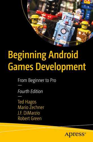
OpenGL ES version distribution
OpenGL ES Version | Distribution |
|---|---|
GL 1.1 only | 0.0% |
GL 2.0 | 14.5% |
GL 3.0 | 18.6% |
GL 3.1 | 9.8% |
GL 3.2 | 57.2% |
OpenGL ES version distribution
Support for one particular version of OpenGL ES also implies support for any lower version (e.g., support for version 2.0 also implies support for 1.1).
It’s important to note that OpenGL ES 2.0 breaks compatibility with the 1.x versions. You can use either 1.x or 2.0, but not both at the same time. The reason for this is that the 1.x versions use a programming model called fixed-function pipeline , while versions 2.0 and up let you programmatically define parts of the rendering pipeline via shaders.
What does OpenGL ES do
A scene management API
A ray tracer
A physics engine
A game engine
A photorealistic rendering engine
OpenGL ES just renders triangles. Not much else.
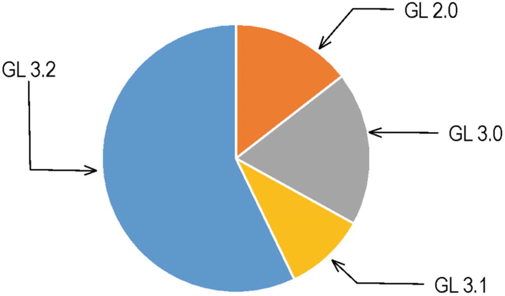
Abstract scene
Each object has a position and orientation relative to the scene’s origin. The camera, indicated by the eye, also has a position in relation to the scene’s origin. The pyramid in Figure 9-2 is called the view volume or view frustum , which shows how much of the scene the camera captures and how the camera is oriented. The little white ball with the rays is the light source in the scene, which also has a position relative to the origin.
We can map this scene to OpenGL ES, but to do so, we need to define (1) models or objects, (2) lights, (3) camera, and (4) viewport.
Models or Objects
OpenGL ES is a triangle rendering machine. OpenGL ES objects are a collection of points in 3D space; their location is defined by three values. These values are joined together to form faces, which are flat surfaces that look a lot like triangles. The triangles are then joined together to form objects or pieces of objects (polygons).
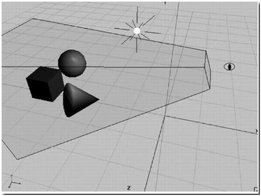
From simple shapes to complex shapes
On the far left of Figure 9-3 is a simple sphere; it doesn’t really go over well as a sphere if you look closely at it. The shape next to it (right) is also a sphere but with more polygons. The shapes, as they progress to the right, form complex contours; this can be achieved by increasing the number of polygons in the shape.
Lights
OpenGL ES offers a couple different light types with various attributes. They are just mathematical objects with positions and/or directions in 3D space, plus attributes such as color.
Camera
This is also a mathematical object that has a position and orientation in 3D space. Additionally, it has parameters that govern how much of the image we see, similar to a real camera. All these things together define a view volume or view frustum (indicated by the pyramid with the top cut off in Figure 9-2). Anything inside this pyramid can be seen by the camera; anything outside will not make it into the final picture.
Viewport
This defines the size and resolution of the final image. Think of it as the type of film you put into your analog camera or the image resolution you get for pictures taken with your digital camera.
Projections
OpenGL ES can construct a 2D bitmap of a scene from the camera’s point of view. While everything is defined in 3D space, OpenGL maps the 3D space to 2D via something called projections . A single triangle has three points defined in 3D space. To render such a triangle, OpenGL ES needs to know the coordinates of these 3D points within the pixel-based coordinate system of the framebuffer that are inside the triangle.
Matrices
A matrix encodes transformations to be applied to a point. A transformation can be a projection, a translation (in which the point is moved around), a rotation around another point and axis, or a scale, among other things.
By multiplying such a matrix with a point, we apply the transformation to the point. For example, multiplying a point with a matrix that encodes a translation by 10 units on the x axis will move the point 10 units on the x axis and thereby modify its coordinates.
We can concatenate transformations stored in separate matrices into a single matrix by multiplying the matrices. When we multiply this single concatenated matrix with a point, all the transformations stored in that matrix will be applied to that point. The order in which the transformations are applied is dependent on the order in which we multiplied the matrices.
Model-view matrix—This matrix is used to place a model somewhere in the “world.” For example, if you have a model of a sphere and you want it located 100 meters to the east, you will use the model matrix to do this. We can use this matrix to move, rotate, or scale the points of our triangles (this is the model part of the model-view matrix). This matrix is also used to specify the position and orientation of our camera (this is the view part). If you want to view our sphere which is 100 meters to the east, we will have to move ourselves 100 meters to the east as well. Another way to think about this is that we remain stationary and the rest of the world moves 100 meters to the west.
Projection matrix—This is the view frustum of our camera. Since our screens are flat, we need to do a final transformation to “project” our view onto our screen and get that nice 3D perspective. This is what the projection matrix is used for.
Texture matrix—This matrix allows us to manipulate texture coordinates.
There’s a lot more theories we need to absorb in OpenGL ES programming, but let’s explore some of those theories alongside a simple coding exercise.
Rendering a Simple Sphere
OpenGL ES APIs are built into the Android framework, so we don’t need to import any other libraries or include any other dependencies into the project.
The manifest entry is basically saying that the app expects the device to support OpenGL ES 2, which is practically all devices at the time of writing.
AndroidManifest.xml, texture compression
activity_main.xml
I removed the default TextView object and inserted a GLSurfaceView element with 400dp by 400dp size. Let’s keep it evenly square for now, so that our shape won’t skew. OpenGL assumes that drawing areas are always square.
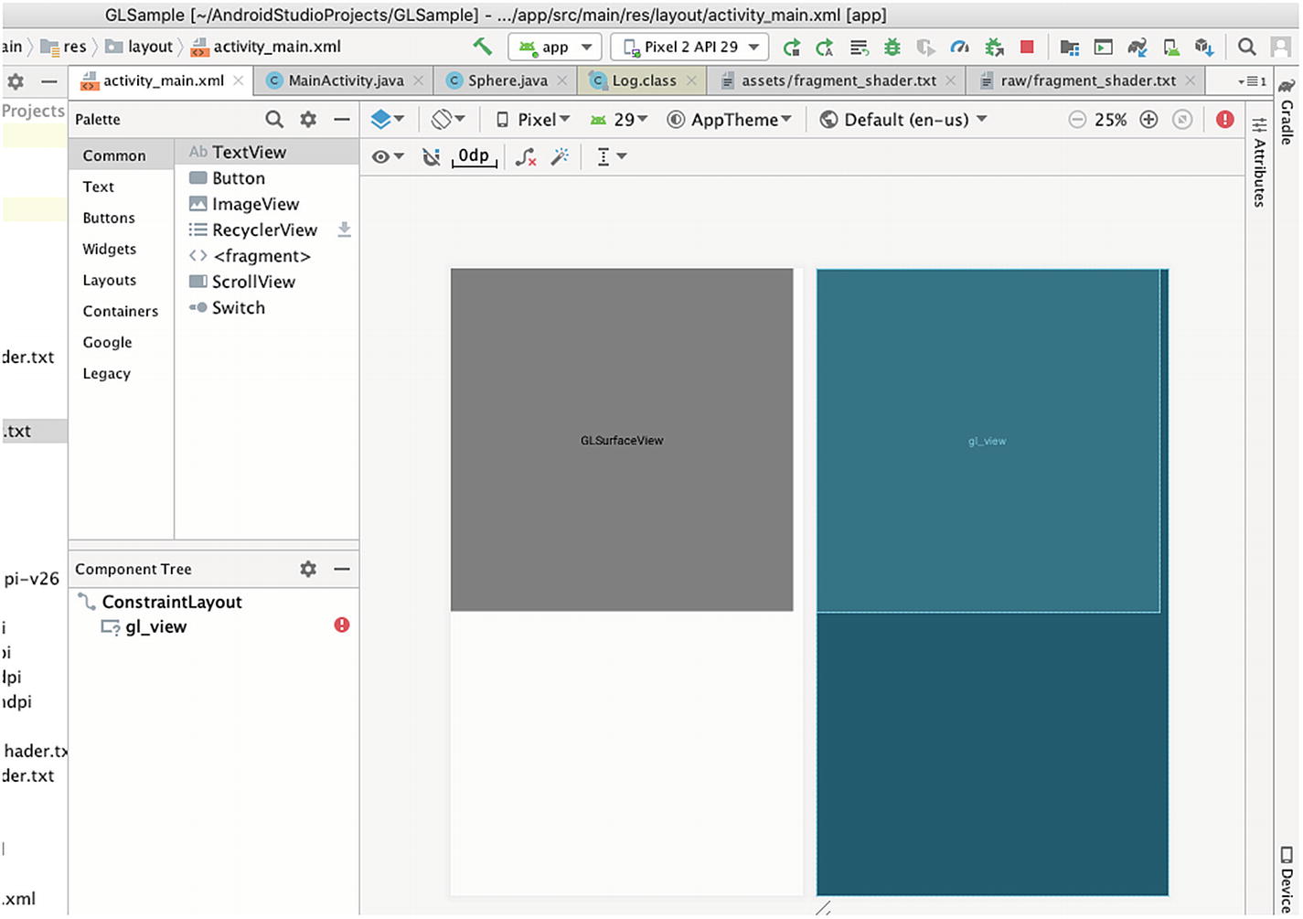
activity_main.xml in design mode
The GLSurfaceView is an implementation of the SurfaceView class that uses a dedicated surface for displaying OpenGL rendering; this object manages a surface, which is a special piece of memory that can be composited into the Android view system. The GLSurfaceView runs on a dedicated thread to separate the rendering performance from the main UI thread.
Get a reference to the GLSurfaceView
Determine support for OpenGL ES 2.0
MainActivity, creation of OpenGL ES 2 environment
❶ | Once we know OpenGL ES 2 is supported, we proceed to creating an OpenGL ES 2 environment. |
❷ | We tell the surface view that we want an OpenGL ES 2 compatible surface. |
❸ | We create a custom renderer using an anonymous class, then passing an instance of that class to the setRenderer() method of the surface view. |
❹ | We’re setting the render mode to draw only when there is a change to the drawing data. |
❺ | This is a good place to create objects you will use for drawing; think of this as the equivalent of the Activity’s onCreate() method. This method may also be called if we lose the surface context and is later recreated. |
❻ | The runtime calls this method once when the surface has been created and subsequently when, for some reason, the size of the surface changes. This is where you set the view port, because by the time this is called, we’ve got the dimensions of the surface. Think of this as the equivalent of the onSizeChanged() of the View class. This may also be called when the device switches orientation, for example, from portrait to landscape. |
❼ | This is where we do our drawing. This is called when it’s time to draw a new frame. |
The onDrawFrame() method of the Renderer is where we tell OpenGL ES to draw something on the surface. We’ll do this by passing an array of numbers which represents positions, colors, and so on. In our case, we’re going to draw a sphere. We can hand-code the arrays of numbers—which represent X,Y,Z coordinates of the vertices—that we need to pass OpenGL ES, but that may not help us to envision what we’re trying to draw. So, instead, let’s use a 3D creation suite like Blender (www.blender.org) to draw a shape.
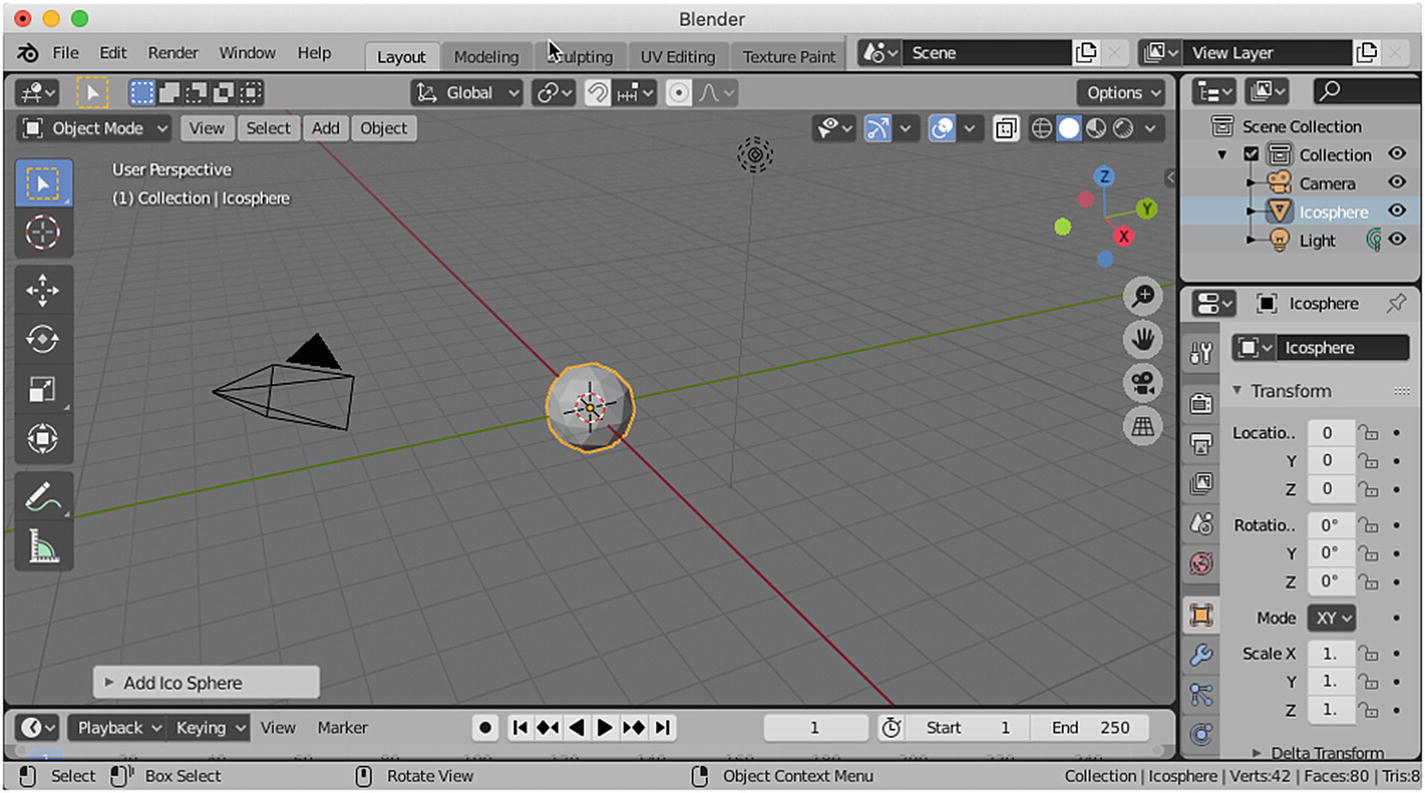
Create an Icosphere
Now we’ve got a moderately interesting object with a couple of vertices—it will be cumbersome to hand-code these vertices; that’s why we took the Blender route.
To use the sphere in our app, we must export it as a Wavefront object. A Wavefront object is a geometry definition file format. It’s an open format and is adopted by 3D graphics application vendors. This is a simple data format that represents 3D geometry, namely, the position of each vertex; the faces that make each polygon are defined as a list of vertices. For our purposes, we’re only interested in the position of the vertices and the faces.
Export as OBJ object
Triangulate faces
Keep vertex order
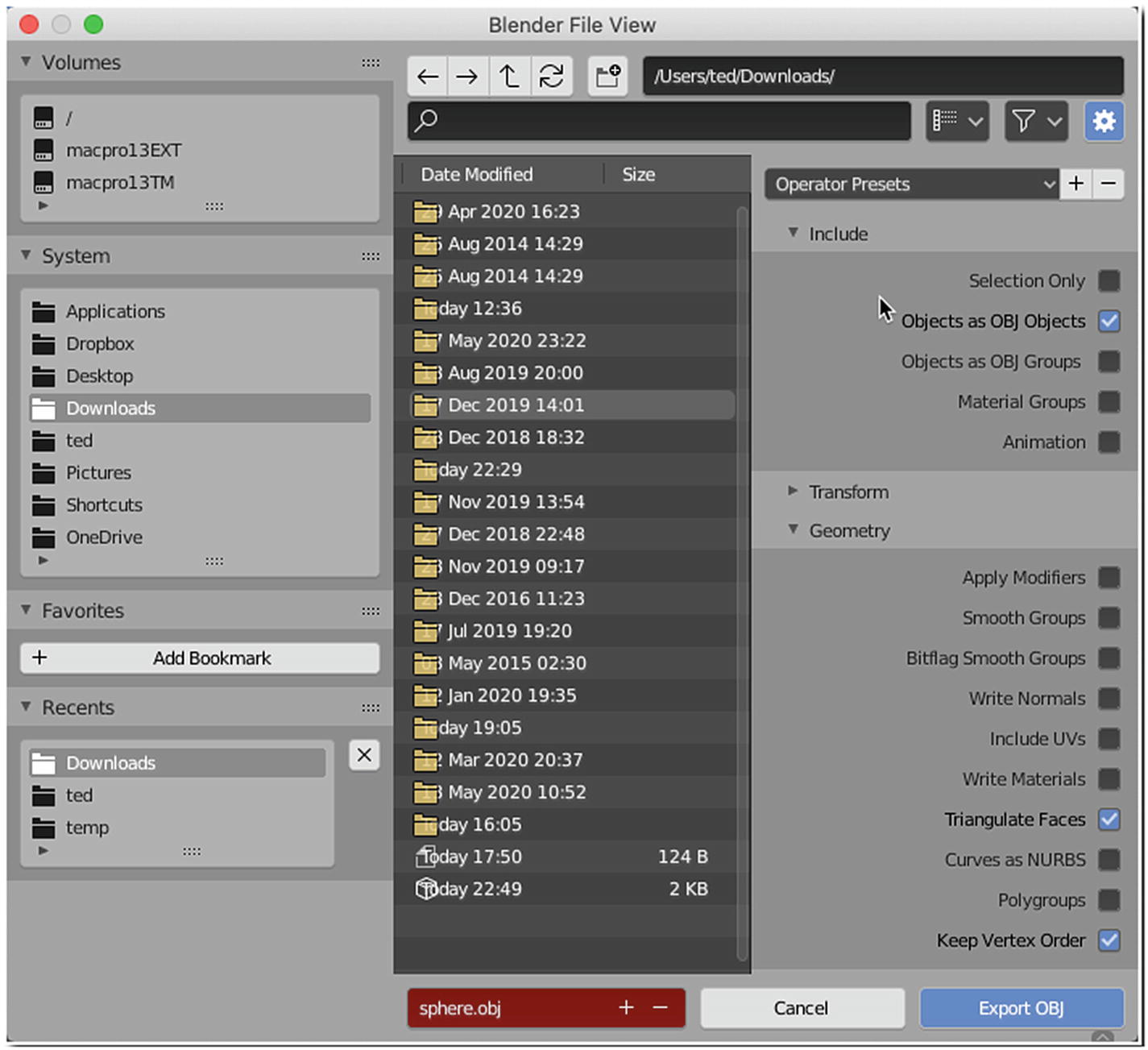
Export the sphere to Wavefront object format
These are the settings I found to be easy to work with, especially when you’re about to parse the exported vertex and faces data.
Partial sphere.obj
Notice how each line starts with either a “v” or an “f”. A line that starts with a “v” represents a single vertex, and a line that starts with an “f” represents a face. The vertex lines have the X, Y, and Z coordinates of a vertex, while the face lines have the indices of the three vertices (which together form a face).
To keep things organized, let’s create a class that will represent our sphere object—we don’t really want to write all the drawing code inside the onDrawFrame() method now, do we?
Create a new class
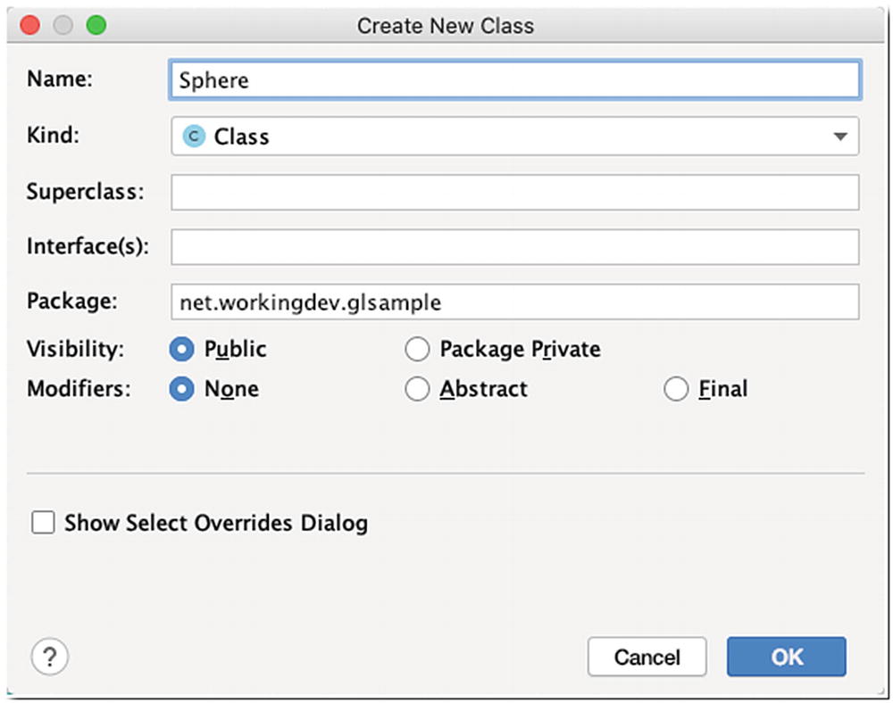
Provide a name for the class
Sphere.java
Context ctx—The context object will be needed by some of our methods, so I made it a member variable.
String TAG—I just need an identifying String for when we do some logging.
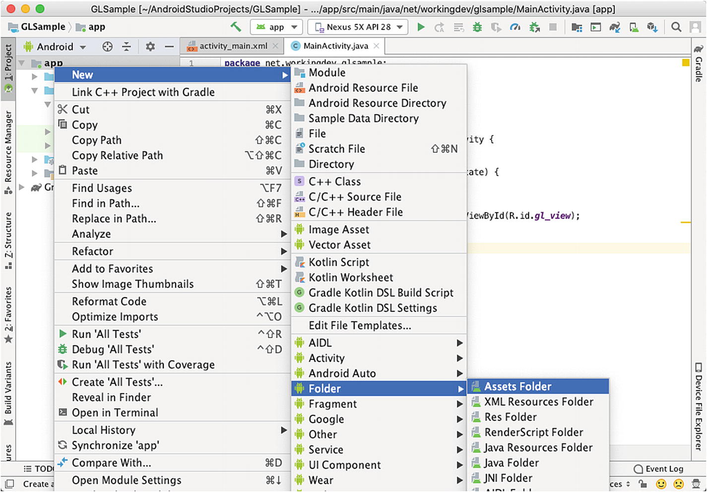
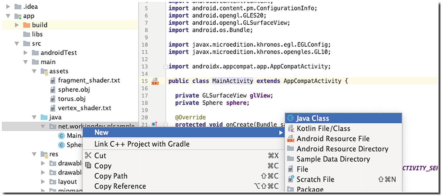
Create an assets folder

New Android component
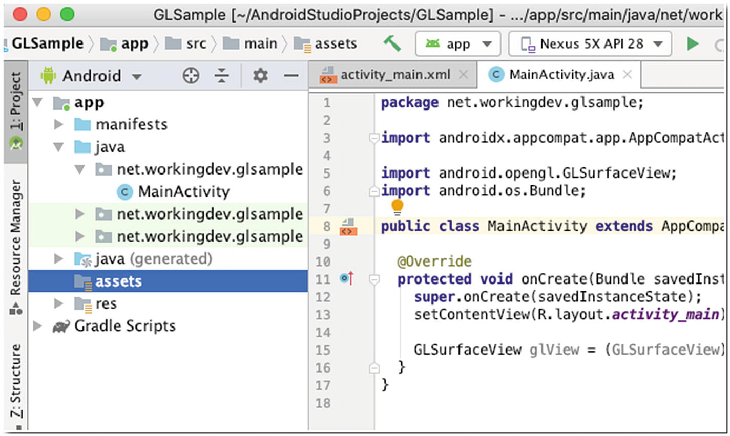
Assets folder created
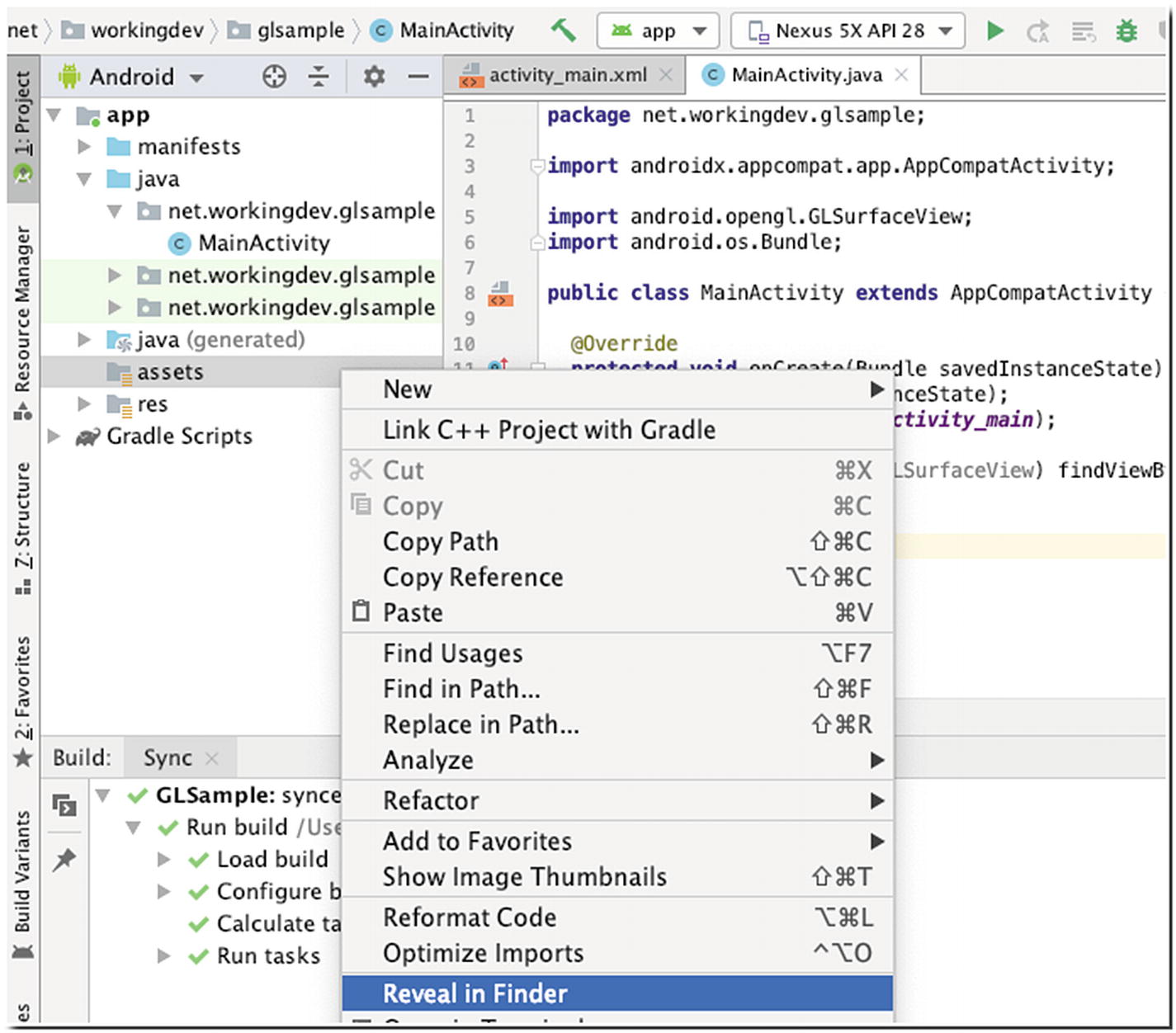
Reveal in Finder or Show in Explorer (for Windows users)
You can now transfer the sphere.obj file to the assets folder of the project.

Copy files using Terminal
Use whichever way is more convenient for you. Some prefer the GUI way, and some prefer the command line. Use the tools you’re more familiar with.
loadVertices()
❶ | Create a new Scanner object and open the sphere.obj text file. |
❷ | While we’re not yet at the end of the file, hasNextLine() will always return true. |
❸ | Read the contents of the current line and save it to the line variable. |
❹ | If the line starts with a “v”, add it to the vertList ArrayList. |
❺ | If the line starts with an “f”, add it to the facesList ArrayList. |
We’re coding our app using the Java language, but you need to remember that OpenGL ES is actually a bunch of C APIs. We can’t simply pass our list of vertices and faces to OpenGL ES directly. We need to convert our vertices and faces data into something OpenGL ES will understand.
createBuffers()
❶ | You have to add FloatBuffer and ShortBuffer member variables to the Sphere class. We will use this to hold the vertices and faces data. |
❷ | Initialize the buffer using the allocateDirect() method. We’re allocating 4 bytes for each coordinate (because they are float numbers). Once the buffer is created, we convert it to a FloatBuffer by calling the asFloatBuffer() method. |
❸ | Similarly, we initialize a ByteBuffer for the faces, but this time, we allocate only 2 bytes for each vertex index, because the indices are unsigned short. Next, we call the asShortBuffer() method to convert the ByteBuffer to a ShortBuffer. |
❹ | To parse the vertices List object, we go through it using Java’s enhanced for-loop. |
❺ | Each entry in the vertices List object is a line that holds the X,Y,Z position of the vertex, like 0.723607 -0.447220 0.525725; it’s separated by a space. So, we use the split() method of the String object using a white space as delimiter. This call will return an array of String with three elements. We convert these elements to float numbers and populate the FloatBuffer. |
❻ | Reset the position of the buffer. |
❼ | Same drill we did like in the vertices List, we split them into array elements, but this time convert them to short. |
❽ | The indices start from 1 (not zero); so, we subtract 1 to the converted value before we add it to the ShortBuffer. |
The next step is to create the shaders. We can’t render our 3D sphere if we don’t create the shaders; we need a vertex shader and a fragment shader. A shader is written in a C-like language called OpenGL Shading Language (GLSL for short).
A vertex shader is responsible for a 3D object’s vertices, while a fragment shader (also called a pixel shader) handles the coloring of the 3D object’s pixels.
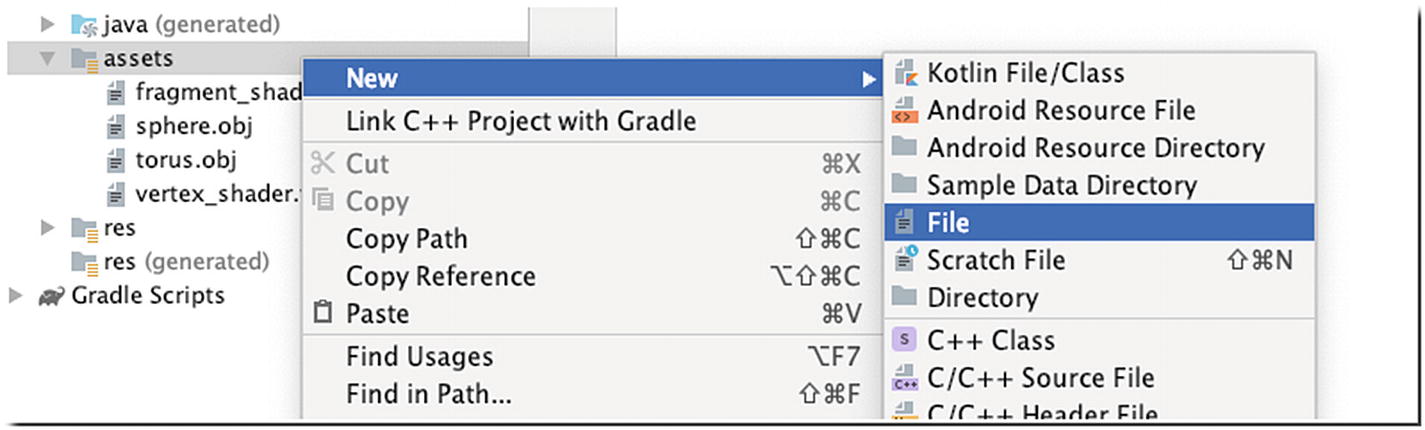
New file
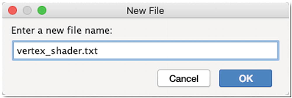
Enter a new file name
vertex_shader.txt
❶ | The attribute global variable receives the vertex position data from our Java program. |
❷ | This is the uniform global variable view-project matrix from our Java code. |
❸ | Inside the main() function, we set the value of gl_position (a GLSL built-in variable) to the product of the uniform and attribute global variables. |
fragment_shader.txt
It’s a minimalistic fragment shader code; it basically assigns a light green color to all the pixels.
createShaders()
❶ | Add member variable declarations for vertexShader and fragmentShader. |
❷ | Open fragment_shader.txt for reading. |
❸ | Open vertex_shader.txt for reading. |
❹ | Create a StringBuffer to hold the partial Strings we will read from the Scanner object; do this for both fragment_shader.txt and vertex_shader.txt. |
❺ | Append the current line to the StringBuffer (do this for both StringBuffer objects). |
❻ | When all the lines in the Scanner object have been read and appended to the StringBuffer, we create a new String object. Do this for both StringBuffers. |
❼ | The shader’s code must be added to the shader objects of OpenGL ES. We create a new shader using the glCreateShader() method, then we set the shader source using the newly created shader and the shader program code; do this for both vertex_shader and fragment_shader. |
❽ | Finally, compile the shaders. |
Before we can use the shaders, we need to link them to a program. We can’t use the shaders directly. This is what connects the output of the vertex shader with the input of the fragment shader. It’s also what lets us pass an input from our program and use the shader to draw our shapes.
runProgram()
❶ | You need to create the program as a member variable in the Sphere class. |
❷ | Use the glCreateProgram() method to create a program. |
❸ | Attach the vertex shader to the program. |
❹ | Attach the fragment shader to the program. |
❺ | To start using the program, we need to link it using the glLinkProgram() method and put it to use via the glUseProgram() method. |
draw()
❶ | You need to import the Matrix class. |
❷ | If you remember in the vertex_shader.txt, we defined a position variable that’s supposed to receive vertex position data from our Java code; we’re about to send that data to this position variable. To do that, we must first get a reference of the position variable in the vertex_shader. We do that using the glGetAttribLocation() method, and then we enable it using the glEnableVertexAttribArray() method. |
❸ | Point the position handle to the vertices buffer. The glVertexAttribPointer() method also expects the number of coordinates per vertex and the byte offset per vertex. Each coordinate is a float, so the byte offset is 3 * 4. |
❹ | Our vertex shader expects a view-projection matrix, which is the product of the view and projection matrices. A view matrix allows us to specify the locations of the camera and the point it’s looking at. A projection matrix lets us map the square coordinates of the Android device and also specify the near and far planes of the viewing frustum. We simply create float arrays for these matrices. |
❺ | Initialize the projection matrix using the frustumM() method of the Matrix class. You need to pass some arguments to this method; it expects the locations of the left, right, bottom, top, near, and far clip planes. When we defined the GLSurfaceView in our activity_main layout file, it’s already a square, so we can use the values -1 and 1 for the near and far clip planes. |
❻ | The setLookAtM() method is used to initialize the view matrix. It expects the positions of the camera and the point it is looking at. Then calculate the product matrix using the multiplyMM() method. |
❼ | Let’s pass the product matrix to the shader using the glGetUniformLocation() method. When we get the handle (the matrix variable), point it to the product matrix using the glUniformMatrix4fv() method. |
❽ | The glDrawElements() method lets us use the faces buffer to create triangles; its arguments expect the total number of vertex indices, the type of each index, and the faces buffer. |
Constructor of the Sphere class
Complete code for the Sphere class
MainActivity, complete
❶ | Create a member variable as a reference to the sphere object we’re about to create. |
❷ | Create the sphere object; pass the current context as an argument. |
❸ | Call the draw() method of the sphere. |
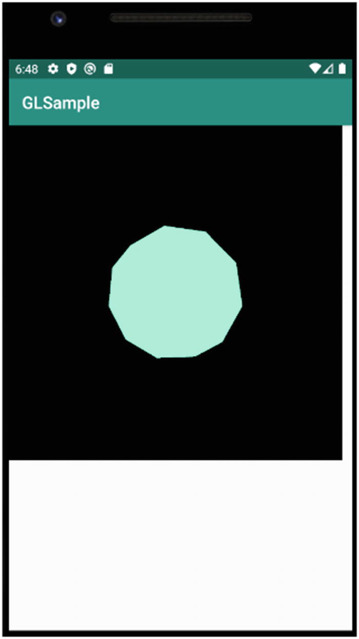
Icosphere rendered in OpenGL ES
After nearly 300 lines of code, all we got was a little green Icosphere without much definition. Welcome to OpenGL ES programming. This should give you an idea how involved and how much work goes into an OpenGL ES game.
Key Takeaways
Starting with Android 3 (API level 11), drawings done on the Canvas already enjoy hardware acceleration, so it’s not a bad choice of tech for game programming. However, if the visual complexities of your game exceed the capabilities of the Canvas, you should consider drawing the graphics using OpenGL ES.
OpenGL ES is really good at just drawing triangles, not much else. It gives you a lot of control though on how you draw those triangles. With it, you can control the camera, the light source, and the texture, among other things.
Android SDK already has built-in support for OpenGL ES. The GLSurfaceView, which is what you will typically use for drawing OpenGL ES objects, is already included in the SDK.