
Thus far into our journey of sensor networks, we have discovered how sensor networks can be formed, the type of nodes, and their roles that comprise a sensor network, and we’ve spent some time learning about XBee modules and how to program them with MicroPython.
Now it is time to see how we can use XBee modules to read sensor data. As you will see, this can be accomplished in one of two ways: using the extensive native capabilities of the XBee to read sensors and broadcast the data to several or even a single node and using MicroPython written to read and manage sensor data passing it on to other nodes. We will concentrate on the first method, but we will see a short example of both methods.
Let’s begin with a brief overview of what we can do with the XBee modules.
How to Host Sensors with XBee
There are two basic methods1 of hosting sensors with an XBee module. You can configure the XBee module to sample a sensor and send its data on a time schedule (XBee hardware option), or you can write a MicroPython script (MicroPython option) to do the same. There is one major difference. Using the MicroPython option means you can do some additional processing on the sensor data prior to transmitting it. This can include basic error handling, data transformation, and more. If you need to do any work on the sensor data prior to transmitting it or if you want to control other devices connected to the XBee module, MicroPython is a clear advantage.
For example, you could connect an LED to the XBee that you turn on whenever data is read from a sensor. This might be helpful in solutions such as a radio frequency identification (RFID) reader where swiping a card over the sensor unlocks a door. In this case, you can use MicroPython to trigger a light-emitting diode (LED) to let the user know when the lock is disengaged (or engaged).
Conversely, the hardware option permits you to configure the XBee to capture the sensor data in its raw form and there is no provision to modify it (easily). Thus, the data sent is the raw data the sensor generated. While this is one of the best practices—storing the data in its raw form—sometimes you may want to manipulate the data prior to transmission. We will see how to do that with the MicroPython option.
In both cases, sensors are connected directly to the XBee via the input/output pins. More specifically, you connect your sensor(s) to the XBee, read the data, and send it to one or more XBee modules on your network. You can send the data to a specific module by address or you can broadcast the data sending it to all modules on the network.
In the next section, we will see examples of both methods using the same hardware setup for a simple environmental sensor.
Building an XBee Environment Sensor
The XBee environmental sensor node in this example is a single XBee module with a simple analog temperature sensor (TMP36) connected to one of the analog input pins, which uses an analog-to-digital converter (ADC) to convert voltage to a number in range 0–1024. For this project, you tell the XBee to send data using short time periods; but for a real project, you would want to consider using a slower sampling rate or perhaps using sleep mode, in which the XBee sleeps for some time, then sends data, and repeats. We set the sampling rate when we configure the XBee module later in this chapter. For now, let’s let the XBee send samples more frequently so you can see something happening.
The XBee also has a really nifty feature for monitoring battery power. You can tell the XBee to send the current supply power as part of the data packet. In this case, it sends whatever voltage is being supplied to the XBee. This is helpful because it allows you to build into your solution a trigger to remind you to change the batteries in your sensor node(s).
If you have a home or apartment with smoke detectors, you may have already experienced a similar circuit in the form of a tone or alarm that sounds when the battery voltage drops. For those of us with homes that have multiple smoke detectors, it can be somewhat of a “Where’s Waldo?” game to find the detector that is chirping! This is why whenever the first detector starts chirping, I change the batteries in all of them.
Hardware Setup
To keep the project easy to build, you will use a breadboard for the sensor node. Using a breadboard makes it easier to experiment with the components, and once you perfect the circuit, you can move them to printed circuit board (PCB) breadboards for semi-permanent installation or perhaps design and build your own custom PCB for your sensor nodes.
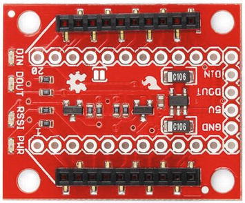
SparkFun regulated XBee Explorer (courtesy of SparkFun)
Most breakout boards do not come with the breadboard headers installed. You have to solder them yourself, get someone to do it for you.
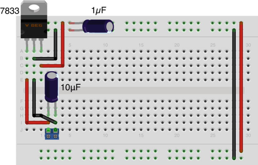
Once you have the components assembled, plug them in to your breadboard as shown in Figure 4-2. Notice the figure is shown without the XBee module installed so you can see the connections clearly. Be sure to set the breadboard power supply to 3.3V.
Be sure to double-check your wiring before powering on the sensor node.

XBee temperature sensor node
It is important to note that the drawing shows positive power going to pin 1 of the XBee. Be sure to check the pins on your breakout board to be certain you are connecting to the right pin. For example, the SparkFun regulated explorer input voltage is not on pin 1.
The breadboard power supply can be any 6V to 12V power supply. The 9V wall wart that most use to power their Arduino will do nicely.
Notice that you also connect your data line from the TMP36 to pin 17 (analog 3 on the XBee or DIO3 on the explorer board), and you connect ground to the ground pin on the breakout board (or explorer). Be sure to orient the TMP36 with the flat side as shown in the drawing. That is, with the flat side facing you, pin 1 is on the left and is to be connected to input power, the middle pin is data, and pin 3 is to be connected to ground. You can place the capacitor in either orientation, but be sure it is connected to pins 1 and 3 of the TMP36.
Ensure your breakout board power supply is set to 3.3V.
If you plan to make a few XBee sensor nodes for semi-permanent installation, you may not want to use a breadboard. Rather, you may want to use a PCB breadboard and solder your XBee breakout board, sensor, and supporting electronics in place. In this case, a breadboard power supply might not be convenient. Similarly, if you want to keep costs down, you can build a basic power supply from a few parts that can accept up to 12V and still regulate the power to your XBee at 3.3V.
You need only a little imagination and some wire to transfer the circuit to a PCB breadboard. Notice the orientation of the capacitors—keep the white strip on the negative side!
Now that we have the hardware portion set up, let’s see how to enable the sensor on the XBee with each method described earlier.
For each option, we will test the sensor node using the XCTU application to observe the data. This will allow us to test reading the sensor without setting up a complete sensor network. In fact, it is recommended that you test each sensor node in a similar manner. Once all of the nodes are working with a single connection, you can start connecting them together in a larger network. This will save you untold time and frustration later.2
We will start with the XBee hardware option.
XBee Hardware Option
In this section, we will use the hardware configuration options of the XBee module to read temperature data from the TMP36 sensor and pass it on to another XBee module on the network. We will use a ZigBee network to keep things simple. More specifically, we will not be using the destination address (DH and DL codes) to set a target node. This will permit the XBee acting as a sensor node to broadcast the data using a data sample packet.
We will need one XBee module to read the sensor and another to receive the data. To keep the example simple and easy to set up, we will use XBee series 2 modules for this example. You can use one of the modules you used in Chapter 2 for the sensor node, provided you don’t use the coordinator and you clear the destination address (DH and DL). You will use the XBee module configured as the coordinator to test the XBee sensor node. The following section details all of the settings you will need to make.
Configuring the XBee Sensor Node
The XBee module you use as the XBee sensor node is either an end device or a router with API firmware. You use the XCTU application to connect to the XBee with a USB adapter. Recall, we must connect the XBee using the USB dongle, then open XCTU, and add the module (or search for all modules). Once the module is found, open the configuration mode tab. From there, we will set several settings to enable the XBee to read the sensor. If you have not uploaded the router or end device firmware, you should do that first.
XBee Sensor Node Options and Values
Code | Setting Name | Description | Value |
|---|---|---|---|
D3 | AD3/DIO3 | Trigger analog or digital data recording | 2—ADC |
ID | PAN ID | Id for the network | 8088 |
IR | I/O Sampling Rate | Time to wait to send data | 3A98—15,000ms |
NI | Node Identifier | Name for the node | Sensor Node |
V+ | Supply Voltage Threshold | Supply voltage | FFFF (always send) |
Setting Up the Coordinator
XBee Coordinator Options and Values
Code | Setting Name | Description | Value |
|---|---|---|---|
ID | PAN ID | Id for the network | 8088 |
NI | Node Identifier | Name for the node | Coordinator |
Now we are ready to test our sensor node.
Testing the XBee Sensor Node
To test the XBee sensor node, you use your XBee coordinator with API firmware installed on the USB adapter connected to your PC. Do this first so the coordinator can be up and running when you start the XBee sensor node. Plug it into your computer, and open the XCTU application. Use XCTU to discover the XBee module and then open a terminal. See Chapter 2 for instructions on how to do this.
Next, connect your power supply to your XBee sensor node. It will take a few moments for the XBee to connect to the coordinator and join the network. Once it does, you start to see the coordinator receiving data, as shown in Figure 4-3.
It can take some time for the network to form. If you do not see data samples on the coordinator, power off the sensor node and power it on again. If you still do not see any data, double-check your settings to ensure both nodes are on the same network PAN ID.
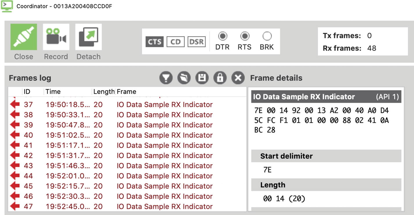
Serial monitor output
IO Data Sample Rx Indicator Packet
Value | Field Name | Notes |
|---|---|---|
7E | Start delimiter | |
00 14 | Packet length | 20 bytes to checksum |
92 | Frame type | I/O Data Sample Rx Indicator |
00 13 A2 00 40 A0 D4 5C | 64-bit address | Address of XBee sensor node |
FC F1 | 16-bit address | |
01 | Options | |
01 | Number of samples | 1 data sample |
00 00 | Digital mask | Digital pins that have data |
88 | Analog mask | Analog pins that have data |
02 41 | Sample | Temperature from sensor |
0A BC | Supply voltage | |
28 | Checksum |
This data packet represents the data sent from the XBee sensor node. In this case, you set the XBee to send any value from the analog pin 3 (digital IO 3) every 15 seconds. You also set the option to send the value of the supply voltage. Notice the value for the analog mask: the value 88 in hexadecimal is converted to 1000 1000 in binary. The first part of the byte is an indicator that the supply voltage is also included in the data packet. The second part of the byte indicates that AD3/DIO3 (pin 3) was the source of the sample. If you were sampling multiple sensors, the mask would have the bits for the data pin set or 0001 for pin 0, 0010 for pin 1, and 0100 for pin 2.
Here, you convert the data read to volts rather than millivolts. Thus, the data packet contained 0A BC (hex, 2748), and the voltage read is 3.22 volts. If you are powering an XBee sensor from a battery, you can use this value to determine when you need to change or charge the battery.
Take a few moments to study the other samples in the example and check the data samples for the temperature read. If you are really careful, you can place your finger on the TMP36 and observe the temperature change (it should start increasing after one or two more samples). Once you are convinced your XBee sensor node is sending similar data, you can conclude that the sensor node is working correctly.
Next, let’s look at the MicroPython option.
MicroPython Option
In this section, we will use a MicroPython script on the XBee module to read temperature data from the TMP36 sensor and pass it on to another XBee module on the network. We will use a ZigBee network to keep things simple. More specifically, we will supply the destination address (DH and DL codes) to send the data to a specific node.
We will need one XBee module to read the sensor and another to receive the data. We must use an XBee series 3 module for the sensor node in this example, but we can use the same coordinator from the previous example. You can use one of the modules you used in Chapter 2 for the sensor node, provided you don’t use the coordinator and you clear the destination address (DH and DL). You will use the XBee module configured as the coordinator to test the XBee sensor node. The following section details all of the settings you will need to make.
Configuring the XBee Sensor Node
The XBee module you use as the XBee sensor node is either an end device or a router with API firmware configured to run MicroPython. Once again, you use the XCTU application to connect to the XBee with a USB adapter.
Recall, we will be placing the XBee module into MicroPython mode. While will we still be using the ZigBee network, we will set up the module to connect to (join) the network. Thus, we will require one coordinator. Fortunately, we can use the same coordinator as the last section.
XBee Sensor Node Options and Values
Code | Setting Name | Description | Value |
|---|---|---|---|
AP | API Enabled | Set API mode | 4—MicroPython |
BD | UART Baud Rate | Speed of serial connection | 115200 |
CE | Device Role | Role in ZigBee Network | 0—Join Network |
D3 | AD3/DIO3 | Trigger analog or digital data recording | 2—ADC |
ID | PAN ID | Id for the network | 8088 |
NI | Node Identifier | Name for the node | Python TMP36 |
PS | MicroPython Auto start | Auto start REPL | 1—Enabled |
Programming the Sensor Node
Go ahead and make the configuration changes for the sensor node and then write (save) them to the module. Recall from Chapter 2, we can either write our MicroPython script interactively and then save it to a file or write it to a file and upload it to the module. In this example, we will see the interactive mode.
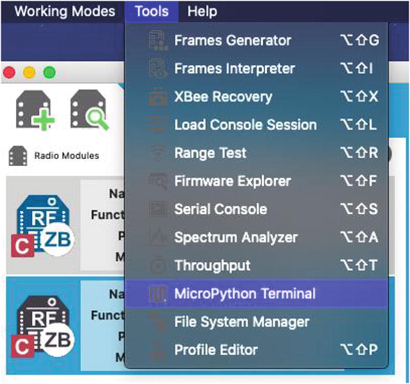
Open MicroPython Terminal
Once the MicroPython Terminal is opened, press Enter a few times to get a response. You should see the prompt >>>. If you are reusing an XBee module from a previous project that was loaded with a MicroPython script where the main.py script was overwritten either by copying a file or using the interactive mode of the REPL console, you may need to press Ctrl+C to stop the main.py script.
Reading a TMP36 Sensor
Listing 4-2 shows the interactive session to copy and paste the preceding code (without comments). Notice at the end, we used Ctrl+D to save the file to main.py, pressing Y to confirm.
If you encounter problems when you copy and paste the entire file, try copy and paste one line at a time. This can happen if you omit the blank lines, which trigger the REPL console to close code blocks and execute code.
Interactive File Mode for TMP36 Sensor Example
Interactive Execution of TMP36 Example
Once you are convinced this formula is correct, you can shut down the MicroPython Terminal, disconnect your XBee from XCTU, and remove the USB explorer. Next, move the XBee module to the breadboard set up from before.
You do not need to power on the circuit, but if you have already configured the coordinator or are using from the previous example, you can power on the circuit skipping the following section.
Setting Up the Coordinator
XBee Coordinator Options and Values
Code | Setting Name | Description | Value |
|---|---|---|---|
ID | PAN ID | Id for the network | 8088 |
NI | Node Identifier | Name for the node | Coordinator |
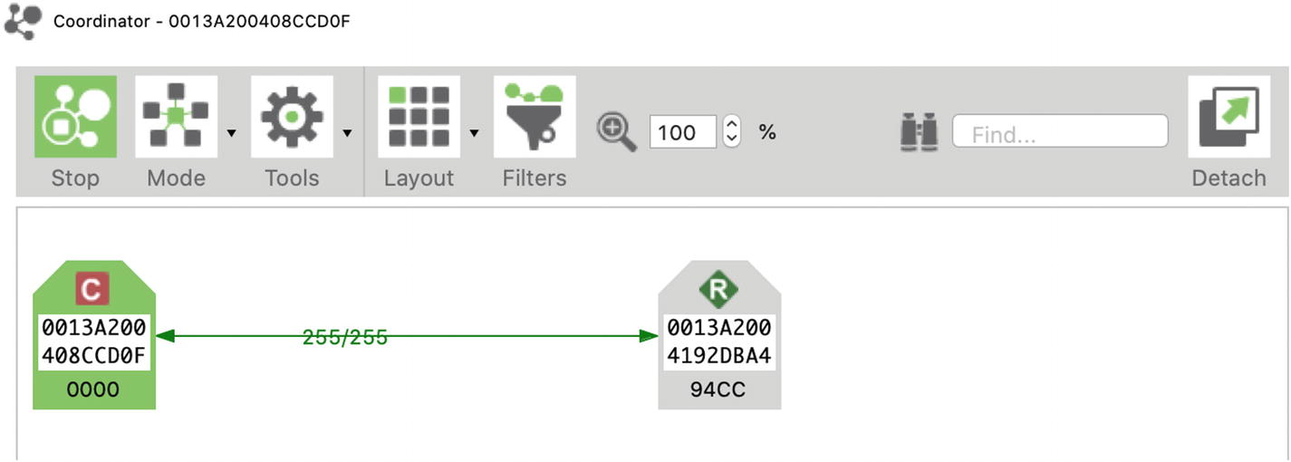
Checking the network
It is always a good idea to check your ZigBee network to ensure the modules have connected correctly. If you do not see the modules you expect, double-check all settings and rescan the network.
Now we are ready to test our sensor node.
Testing the XBee Sensor Node
To test the XBee sensor node, you use your XBee coordinator with API firmware installed on the USB adapter connected to your PC. Do this first so the coordinator can be up and running when you start the XBee sensor node. Plug it into your computer, and open the XCTU application. Use XCTU to discover the XBee module and then open a terminal. See Chapter 2 for instructions on how to do this.
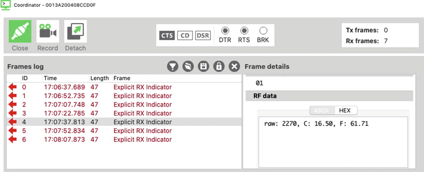
Serial monitor output
Explicit Rx Indicator Packet
Value | Field Name | Notes |
|---|---|---|
7E | Start delimiter | |
00 2F | Packet length | 47 bytes to checksum |
91 | Frame type | Explicit Rx Indicator |
00 13 A2 00 41 92 DB A4 | 64-bit address | Address of XBee sensor node |
94 CC | 16-bit address | |
E8 | Source endpoint | |
E8 | Destination endpoint | |
00 11 | Cluster Id | |
C1 05 | Profile Id | |
01 | Receive options | 0x01—Packet Acknowledged |
0A BC | Supply voltage | |
N bytes | Received data | Example: 29 |
N+1 byte | Checksum | Example: 0x24 |
This data packet represents the data sent from the XBee sensor node. In this case, you set the XBee to send any value from the analog pin 3 (digital IO 3) every 15 seconds for ten cycles.4
Take a few moments to study the other samples in the example and check the data samples for the temperature read. If you are really careful, you can place your finger on the TMP36 and observe the temperature change (it should start increasing after one or two more samples). Once you are convinced your XBee sensor node is sending similar data, you can conclude that the sensor node is working correctly.
Next, we will look at an example of this project done a bit easier using a different form of sensor.
Example: Using XBee Modules to Gather Data
In this example, we will kick up the configuration a bit by switching to an easier (but slightly more expensive) option to connect sensors to XBee modules. We will also see a different form of sensor that communicates with a different interface.

XBee Grove Development Board
Grove is a hardware prototyping standard made by Seeed Studio (seeedstudio.com) designed to simplify connecting devices together using a simple, four-wire connection. You can find all manner of sensors and output components for creating your projects quickly. See the Seeed Studio wiki about the Grove system to learn more (http://wiki.seeedstudio.com/Grove_System/).
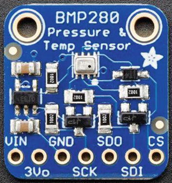
BMP280 breakout board
This sensor uses the Inter-Integrated Circuit (I2C) interface5 with 7-bit addressing. This requires four connections: power, ground, clock (SCL), and data (SDA). Since you can connect multiple sensors to the same I2C bus, each sensor has its own address so that you can “talk” to the sensor you want. Unfortunately, each I2C sensor (device) has its own communication protocol, so communicating with the module to get data requires a special library (called a driver) to use the sensor. Fortunately, there is a MicroPython I2C driver for the BMP280. We will download it and copy it to our XBee module. However, since it is written to a MicroPython version that is a bit different than the XBee MicroPython, we need to make some minor alterations.
While this example is terse and shows the bare minimal needed to get it working, we will learn more about I2C interfaces in the next two chapters.
Let’s begin by configuring the hardware for the XBee sensor node.
Hardware Setup
Setting up the hardware for this project is easier than the previous examples. All you need is a Grove to Female Jumper cable or (4) female-to-female jumper wires, the XBee Grove Development Board, and the BMP280 module. If your BMP280 module doesn’t have the header soldered, you may need to solder it yourself or find someone to solder it for you.
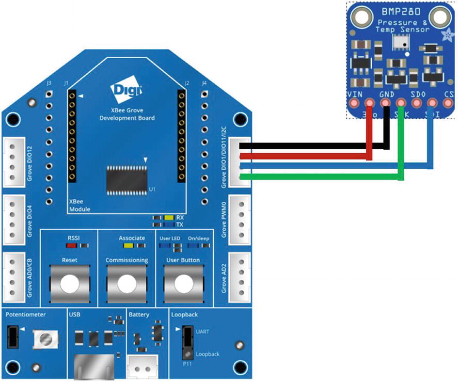
To connect the sensor to the board, we will be using only four of the connections on the BMP280. The module from Adafruit supports I2C and x (SPI) interfaces, so we only need those for I2C. These are marked on the board as follows: 3V0 (3V power), GND (ground), SDK (SCL on the development board), and SDI (SDA on the development board). We can use the Grove PWM connector for power and ground, but must use the Grove D10 connector for the I2C interface. Several options for making the connections are shown as follows. Go ahead and make the connections now. Do not insert the XBee module or connect the board to your PC at this time.
BMP280 with Jumper Wires
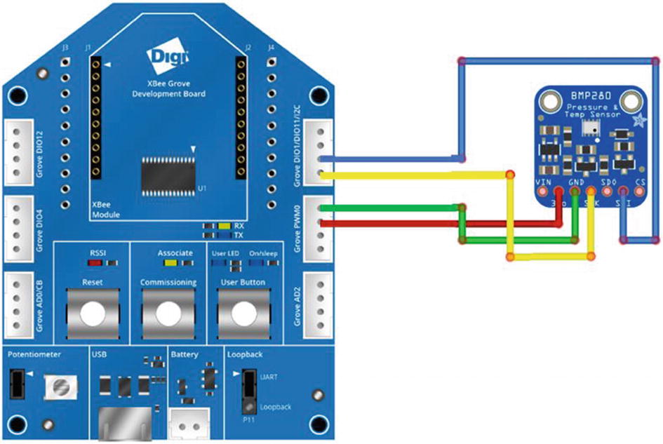
Connecting the BMP280 breakout board using jumper wires
BMP280 with Grove Breakout Cable
The Grove breakout cable from Seeed Studio is an excellent alternative to jumper wires. These have a Grove connector on one end and female connectors for each wire on the other end, making them ideal for connecting to breakout boards like the BMP280 in this example. See www.seeedstudio.com/Grove-4-pin-Female-Jumper-to-Grove-4-pin-Conversion-Cable-5-PCs-per-Pack.html for more details. Like the Grove BMP280 module, these cables are harder to find. They also make a Grove to male cable. See www.seeedstudio.com/Grove-4-pin-Male-Jumper-to-Grove-4-pin-Conversion-Cable-5-PCs-per-Pack.html.
Connecting the BMP280 breakout board using Grove to jumper wire cable
Grove BMP280 Module Connections

Connecting the BMP280 Grove module
Next, let’s configure the XBee sensor node.
Configuring the XBee Sensor Node
The XBee module you use as the XBee sensor node is either an end device or a router with API firmware configured to run MicroPython. Once again, you use the XCTU application to connect to the XBee. In this case, we will use the XBee Grove Development Board.
Simply connect your XBee module to the board and then connect the board to your PC using the provided micro-USB cable. This will act like the USB explorer that we’ve been using in the other projects. If you are reusing the XBee module we used as the sensor node from the previous, many of the settings will remain the same except for the digital IO pin setting (D1).
XBee Sensor Node Options and Values
Code | Setting Name | Description | Value |
|---|---|---|---|
AP | API Enabled | Set API mode | 4—MicroPython |
BD | UART Baud Rate | Speed of serial connection | 115200 |
CE | Device Role | Role in ZigBee Network | 0—Join Network |
D1 | DIO1 | Digital data read/write | 6—I2C SCL |
ID | PAN ID | Id for the network | 8088 |
NI | Node Identifier | Name for the node | Python BMP280 |
PS | MicroPython Auto start | Auto start REPL | 1—Enabled |
Programming the Sensor Node
Go ahead and make the configuration changes for the sensor node and then write (save) them to the module. Recall from Chapter 2, we can either write our MicroPython script interactively and then save it to a file or write it to a file and upload it to the module. In this example, we will see the file copy mode.
In this case, we will need to copy the BMP280 I2C library to the lib folder on the XBee module and copy our MicroPython script to the XBee module renaming it as main.py. Rather than jumping into the project by blindly copying the files, let’s learn how to use custom MicroPython libraries using the BMP280 library.
When you want to use an I2C sensor or device, you will need to have a MicroPython driver library for it. Recall, this is because each device has its own protocol requiring writing certain values to a specific byte or bytes to trigger or set some option and then read the data using yet another address. Sound complicated? It can be. Fortunately, someone has done all the work for us.
Use your browser and navigate to https://github.com/dafvid/micropython-bmp280/. This library was written by David Wahlund and is an excellent example of how to write an I2C driver in MicroPython. If you want to write your own driver for another I2C device, this code is a very good template to follow.
To download the driver, click the Clone or download button and save the Zip file to your PC. Once it has downloaded, open the Zip library and extract the files. You will need to find the bmp280.py file. We will be copying this file to our XBee module after we modify it.
A modified version of the module is available on the source code download for the book from the Apress website.
In short, we must add a new import and comment out a few lines in the constructor. These modifications will permit the code to work on the XBee modules. We also need to remove some of the methods in the module because the code size is a bit too large for the XBee.
If you find other modules you want to use with your XBee and encounter memory errors, you may need to reduce the size of the module. You can do so by removing unneeded methods, constants, and similar features. Be careful to only remove things you don’t need (and are not needed by the remaining methods).
Finally, to reduce the size of the module, remove all methods after the pressure() method and then save the file. Listing 4-4 shows the resulting code. Your edits should be very similar (allowing for minor improvements by the author of the module).
Also included in the source code for the book is a difference file (bmp280.diff) that you can use to apply to the code if you are familiar with diff and patch.
Modified bmp280.py Module

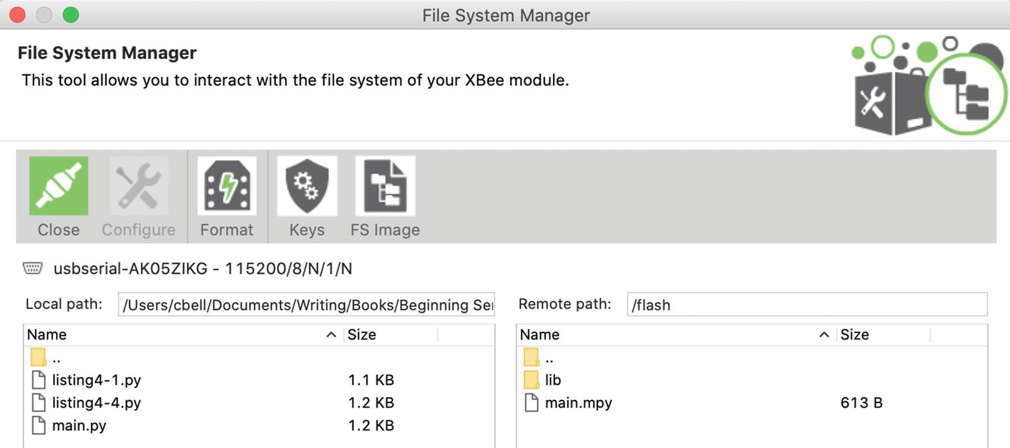
Open the File System Manager
Once the File System Manager is open, you will need to connect to the XBee. If you select the XBee module in XCTU before opening the File System Manager, you can click the Open button and the manager will connect to your module. Otherwise, you can use the Settings button to choose the UART (serial) parameters for the XBee and then connect to it.

Copying the BMP driver using the File System Manager
Now, let’s test the library using a bare minimal script. We’ll use the MicroPython Terminal in interactive mode to do that. But first, click the Close button in the upper left and then the Close button in the lower right to close the manager.
If you get errors such as address or NOENV errors, double-check your wiring connections. Sometimes the jumper wires can be a little loose. Crimp them on the development board side and the connection should improve.
Reading a BMP280 Sensor
Copying the main.py using the File System Manager
Now we are ready to test our sensor node.
Testing the XBee Sensor Node
To test the XBee sensor node, you use your XBee coordinator with API firmware installed on the USB adapter connected to your PC. Do this first so the coordinator can be up and running when you start the XBee sensor node. Plug it into your computer, and open the XCTU application. Use XCTU to discover the XBee module and then open a terminal. See Chapter 2 for instructions on how to do this.

Serial monitor output
Receive Packet Packet
Value | Field Name | Notes |
|---|---|---|
7E | Start delimiter | |
00 2E | Packet length | 47 bytes to checksum |
90 | Frame type | Receive Packet Indicator |
00 13 A2 00 41 92 DB A4 | 64-bit address | Address of XBee sensor node |
94 CC | Reserved | |
01 | Options | 0x01 = Packet was a broadcast packet |
N bytes | Received data | Example: 34 |
N+1 byte | Checksum | Example: 0x58 |
Take a few moments to study the other samples in the example and check the data samples for the temperature read. If you are really careful, you can place your finger on the BMP280 and observe the temperature change (it should start increasing after one or two more samples). Once you are convinced your XBee sensor node is sending similar data, you can conclude that the sensor node is working correctly.
Component Shopping List
Components Needed
Item | Vendors | Est. Cost USD | Qty Needed |
|---|---|---|---|
XBee-ZB (ZB) Series 2, 2.5, or 3 | $25.00–48.00 | 2 | |
BMP280 breakout board | $9.95–14.95 | 1 | |
BMP280 Grove Sensor (optional) | $8.95 | 1 | |
Grove to Female Jumper (optional) | www.seeedstudio.com/Grove-4-pin-Female-Jumper-to-Grove-4-pin-Conversion-Cable-5-PCs-per-PAck.html | $3.90 | 1 |
XBee Grove Development Board (optional) | $25.00 | 1 | |
Breadboard (not mini) | $4.95 | 1 | |
Breadboard jumper wires | $3.95 | 1 | |
XBee Explorer Regulated with headers | $10.95 | 1 | |
TMP36 sensor | $1.50 | 1 | |
0.10uF capacitor | $0.25 | 1 |
Summary
The XBee modules are a fantastic inexpensive way to transmit data wirelessly from one device to another. They can also be used to collect data in the form of hosting (connecting) one or more sensors.
We can either configure the XBee to collect the raw data from the sensor and transmit (broadcast) it to other nodes in the network—without programming. Or, we can use the robust MicroPython programming language to write a script to read the data and format it or perform calculations before sending it to another node.
In this chapter, we saw examples of both forms of hosting sensors. We learned how to connect sensors to the XBee module using an analog temperature sensor (TMP36) as well as an I2C digital sensor (BMP280).
We also saw a short glimpse at the Grove prototyping platform offered by Seeed Studio. Grove makes connecting sensors easier by removing the need to build circuits on a breadboard. We will see more about Grove sensors in later chapters.
In the next chapter, we will explore the Raspberry Pi including a short tutorial on how to use the Raspberry Pi as well as example projects on how to host sensors.