
One of the greatest advances in physical computing has been the proliferation of microcontrollers. A microcontroller consists of a processor with a small instruction set, memory, and programmable input/output circuitry contained on a single chip. Microcontrollers are usually packaged with supporting circuitry and connections on a small printed circuit board.
Microcontrollers are used in embedded systems where small software programs can be tailored to control and monitor hardware devices, making them ideal for use in sensor networks. One of the most successful and most popular microcontrollers is the Arduino platform.
In this chapter, you explore the Arduino platform with the goal of using the Arduino to manage sensor nodes. You see a short tutorial on the Arduino and several projects to help get you started working with the Arduino.
What Is an Arduino?
The Arduino is an open source hardware prototyping platform supported by an open source software environment. It was first introduced in 2005 and was designed with the goal of making the hardware and software easy to use and available to the widest audience possible. Thus, you do not have to be an electronics expert to use the Arduino.
The original target audience included artists and hobbyists who needed a microcontroller to make their designs and creations more interesting. However, given its ease of use and versatility, the Arduino has quickly become the choice for a wider audience and a wider variety of projects.
This means you can use the Arduino for all manner of projects from reacting to environmental conditions to controlling complex robotic functions. The Arduino has also made learning electronics easier through practical applications.
Another aspect that has helped the rapid adoption of the Arduino platform is the growing community of contributors to a wealth of information made available through the official Arduino website (http://arduino.cc/en/). When you visit the website, you find an excellent “getting started” tutorial as well as a list of helpful project ideas and a full reference guide to the C-like language for writing the code to control the Arduino (called a sketch).
Arduino also provides an integrated development environment called the Arduino IDE. The IDE runs on your computer (called the host), where you can write and compile sketches and then upload them to the Arduino via USB connections. The IDE is available for Linux, Mac, and Windows. It is designed around a text editor especially designed for writing code and a set of limited functions designed to support compilation and loading of sketches.
Sketches are written in a special format consisting of only two required methods—one that executes when the Arduino is reset or powered on and another that executes continuously. Thus, your initialization code goes in setup() and your code to control the Arduino goes in loop(). The language is C-like, and you may define your own variables and functions. For a complete guide to writing sketches, see http://arduino.cc/en/Tutorial/Sketch.
You can expand the functionality of sketches and provide for reuse by writing libraries that encapsulate certain features such as networking, using memory cards, connecting to databases, doing mathematics, and the like.
The Arduino supports a number of analog and digital pins that you can use to connect to various devices and components and interact with them. The mainstream boards have specific pin layouts, or headers, that allow the use of expansion boards called shields. Shields let you add additional hardware capabilities such as Ethernet, Bluetooth, and XBee support to your Arduino. The physical layout of the Arduino and the shield allow you to stack shields. Thus, you can have an Ethernet shield as well as an XBee shield, because each uses different I/O pins. You learn the use of the pins and shields as you explore the application of Arduino to sensor networks.
The next sections examine the various Arduino boards and briefly describe their capabilities. I list the boards by when they became available, starting with the most recent models. Many more boards and variants are available, and a few new ones are likely to be out by the time this book is printed, but these are the ones that are typically used in a sensor network project.
Arduino Models
A growing number of Arduino boards are available. Some are configured for special applications, whereas others are designed with different processors and memory configurations. Some boards are considered official Arduino boards because they are branded and endorsed by Arduino.cc. Since the Arduino is licensed using a Creative Commons Attribution Share-Alike license, anyone can build Arduino-compatible boards if they adhere to the license. This section examines some of the more popular Arduino-branded boards.
The basic layout of an Arduino board consists of a USB connection, a power connector, a reset switch, LEDs for power and serial communication, and a standard spaced set of headers for attaching shields. The official boards sport a distinctive blue-colored PCB with white lettering. With the exception of one model, all the official boards can be mounted in a chassis (they have holes in the PCB for mounting screws). The exception is an Arduino designed for mounting on a breadboard.
Uno
The Uno board is the standard Arduino board that most new to the Arduino will choose. It features an ATmega328P processor; 14 digital I/O pins, of which 6 can be used as pulse-width modulation (PWM)1 output; and 6 analog input pins. The Uno board has 32KB of flash memory and 2KB of SRAM.

Arduino Uno Rev3 (courtesy of Arduino.cc)

Arduino Uno Wi-Fi Rev2 (courtesy of Arduino.cc)
Leonardo
The Leonardo board represents another of the standard boards in the pantheon of Arduino platform. It is a little different in that, while it supports the standard header layout, it also has a USB controller that allows the board to appear as a USB device (e.g., mouse or keyboard) to the host computer. The board uses a newer ATmega32u4 processor with 20 digital I/O pins, of which 12 can be used as analog pins and 7 can be used as a pulse-width modulation (PWM) output. It has 32KB of flash memory and 2.5KB of SRAM.
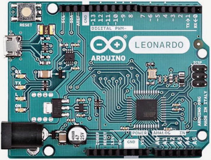
Arduino Leonardo (courtesy of Arduino.cc)
Due
32-bit registers
DMA controller (allows CPU-independent memory tasks)
512KB flash memory
96KB SRAM
84MHz clock
The Due has the larger form factor (called the mega footprint) but still supports the use of standard shields as well as mega format shields. The new board has one distinct limitation: unlike other boards that can accept up to 5V on the I/O pins, the Due is limited to 3.3V on the I/O pins. Details and a full datasheet can be found at https://store.arduino.cc/usa/due.
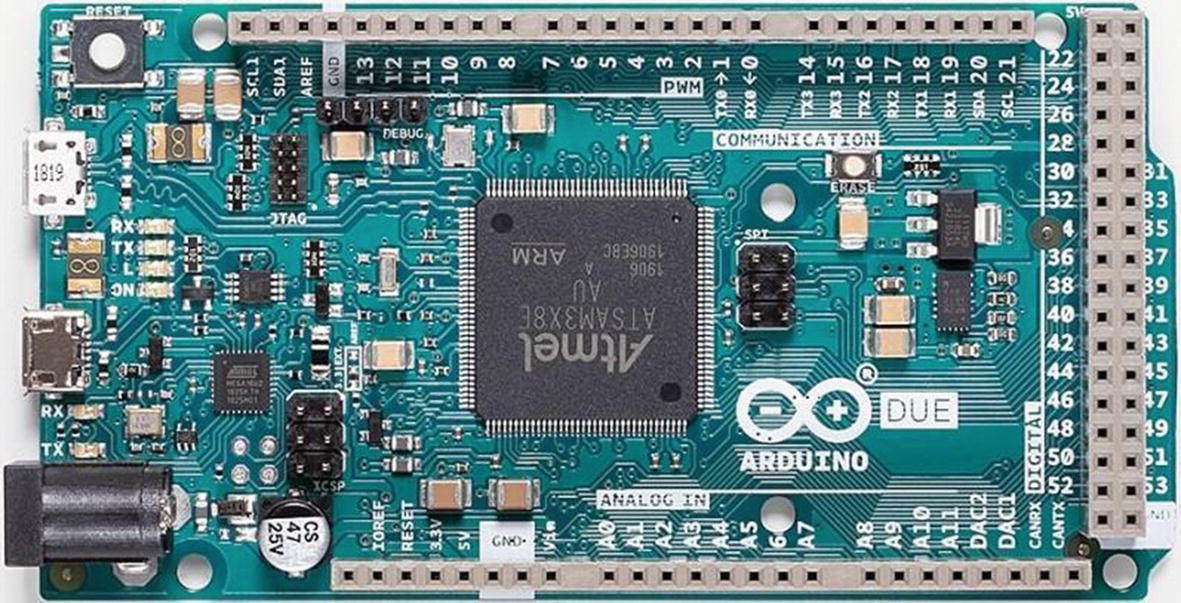
Arduino Due (courtesy of Arduino.cc)
Mega 2560
The Arduino Mega 2560 is an older form of the Due. It is based on the ATmega2560 processor (hence the name). Like the Due, the board supports a massive 54 digital I/O ports, of which 14 can be used as PWM output, 16 analog inputs, and 4 UARTs (hardware serial ports). It uses a 16MHz clock and has 256KB of flash memory. Details and a full datasheet can be found at https://store.arduino.cc/usa/mega-2560-r3.
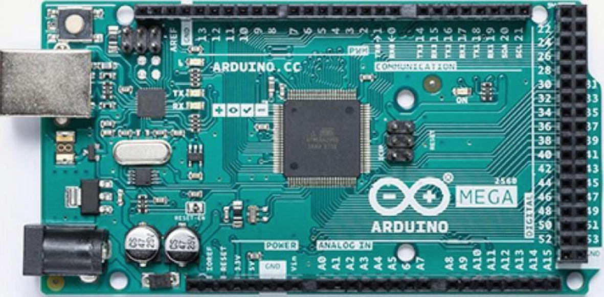
Arduino Mega (courtesy of Arduino.cc)
Interestingly, the Arduino Mega 256 is the board of choice for Prusa Mendel and similar 3D printers that require the use of a controller board named RepRap Arduino Mega Pololu Shield (RAMPS).
Notice how much larger the Due is than the Uno. If you choose to incorporate a Due, Mega, or similar board, you may have to set aside more room to mount the board.
Micro
The Arduino Micro is a special form of the Leonardo board and uses the same processor with 20 digital I/O pins, of which 12 can be used as analog pins and 7 can be used as PWM output. It has 32KB of flash memory and 2.5KB of SRAM. Details and a full datasheet can be found at https://store.arduino.cc/usa/arduino-micro.
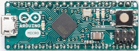
Arduino Micro (courtesy of Arduino.cc)
Although branded as an official Arduino board, the Arduino Micro is produced in cooperation with Adafruit.
Nano
The Arduino Nano is an older form of the Arduino Micro. In this case, it is based on the functionality of the Duemilanove4 and has the ATmega328 processor (older models use the ATmega168) and 14 digital I/O pins, of which 6 can be used as PWM output and 8 analog inputs. The mini has 32KB of flash memory and uses a 16MHz clock. Details and a full datasheet can be found at https://store.arduino.cc/usa/arduino-nano.
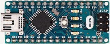
Arduino Nano (courtesy of Arduino.cc)
MKR-Series Boards
There is another form of Arduino called the MKR (for “maker”) series. The MKR series includes a variety of boards based on the (now retired Zero) board that have various communication capabilities such as Wi-Fi, LoRa, LoRaWAN, and GSM.
They are based on the Atmel ATSAMW25 SoC (System on Chip) and designed for IoT projects and devices. It also supports cryptographic authentication. For those working on projects that require battery port, the MKR series of boards include a LiPo charging circuit for charging a LiPo battery while running on external power. Details and a full datasheet can be found at https://store.arduino.cc/usa/arduino-mkr1000.

MKR1000 (courtesy of Arduino.cc)
The MKR boards run on 3.3V power and have a maximum input on the GPIO pins of 3.3V.
Arduino Clones
A growing number of Arduino boards are available from a large number of sources. Because the Arduino is open hardware, it is not unusual or the least bit illicit to find Arduino boards made by vendors all over the world.
Although some would insist the only real Arduinos are those branded as such, the truth of the matter is that as long as the build quality is sound and the components are of high quality, the choice of using a branded vs. a copy, hence clone, is one of personal preference. I have sampled Arduino boards from a number of sources, and with few exceptions, they all perform their intended functions superbly.
Except for the Arduino Mini, the Arduino clone boards have a greater variety of hardware configurations. Some Arduinos are designed for use in embedded systems or on breadboards, and some are designed for prototyping. I examine a number of the more popular clone boards in the following sections.
Arduino Pro Mini
The Arduino Pro Mini is another board from SparkFun. It is based on the ATmega168 processor (older models use the ATmega168) and has 14 digital I/O pins, of which 6 can be used as PWM output, and 8 analog inputs. The Pro Mini has 16KB of flash memory and 1KB of SRAM, and it uses a 16MHz clock. Details and a full datasheet can be found at www.sparkfun.com/products/11113.

Arduino Pro Mini (courtesy of SparkFun)
Also, the Pro Mini does not include a USB connector and therefore must be connected to and programmed with a FTDI cable or similar breakout board. It comes as either a 3.3V model with an 8MHz clock or a 5V model with a 16MHz clock.
Fio
The Arduino Fio is yet another board made by SparkFun. It was designed for use in wireless projects. It is based on the ATmega32U4 processor with 14 digital I/O pins, of which 6 can be used as PWM outputs, and 8 analog pins. Details and a full datasheet can be found at www.sparkfun.com/products/11520.
The Fio requires a 3.3V power supply, which allows for use with a lithium polymer (LiPo) battery which can be recharged via the USB connector on the board.

Arduino Fio (courtesy of SparkFun)
Seeeduino
The Seeeduino is an Arduino clone made by Seeed Studio (www.seeedstudio.com). It is based on the ATmega328P processor and has 14 digital I/O pins, of which 6 can be used as PWM outputs, and 8 analog pins. It has 32KB of flash memory and 2KB of SRAM. Details and a full datasheet can be found at www.seeedstudio.com/Seeeduino-V4-2-p-2517.html.

Seeeduino (courtesy of Seeed Studio)
Seeed Studio also makes a “mini” version of this board ().
Sippino
The Sippino from SpikenzieLabs (www.spikenzielabs.com) is designed to be used on a solder-less breadboard. It costs less because it has fewer components and a much smaller footprint. It comes unassembled and, if you are learning to solder, can make for a very enjoyable afternoon project.
It is based on the ATmega328 processor and has 14 digital I/O pins, of which 6 can be used as PWM output, and 6 analog input pins. The Sippino board has 32KB of flash memory and 2KB of SRAM. Details and a full datasheet can be found at www.spikenzielabs.com/Catalog/arduino/sippino-prototino-8482/sippino-kit?cPath=1&.
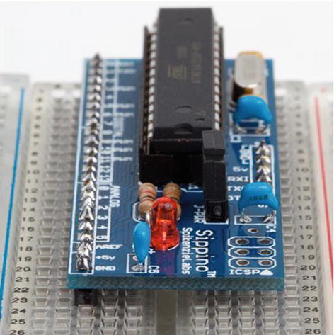
Sippino (courtesy of SpikenzieLabs)
SpikenzieLabs also makes a version with a USB connector (www.spikenzielabs.com/Catalog/arduino/sippino-prototino-8482/sippino8482-usb-kit?cPath=1&).
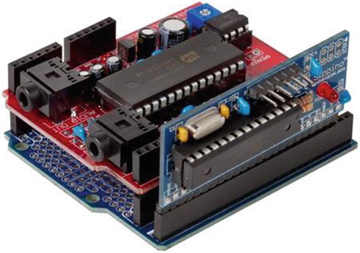
Sippino on a shield dock (courtesy of SpikenzieLabs)
Prototino
The Prototino is another product of SpikenzieLabs. It has the same components as the Sippino, but instead of a breadboard-friendly layout, it is mounted on a PCB that includes a full prototyping area. Like the Sippino, it is based on the ATmega328 processor and has 14 digital I/O pins, of which 6 can be used as PWM output, and 6 analog input pins. The Prototino board has 32KB of flash memory and 2KB of SRAM. Details and a full datasheet can be found at www.spikenzielabs.com/Catalog/arduino/sippino-prototino-8482/prototino?cPath=1&.
The Prototino is ideal for building solutions that have supporting components and circuitry. In some ways, it is similar to the Nano, Mini, and similar boards, in that you can use it for permanent installations. But unlike those boards (and even the Arduino Pro), the Prototino provides a space for you to add your components directly to the board. I have used a number of Prototino boards for projects where I have added the components to the Prototino and install it in the chassis. This allowed me to create a solution using a single board and even build several copies quickly and easily.

Prototino (courtesy of SpikenzieLabs)
Metro from Adafruit

Metro 328 (courtesy of Adafruit)
Adafruit also has several CircuitPython models. Some are smaller and thus may be an option if you need to minimize the footprint of your node. For more details, see www.adafruit.com/category/966.
Every now and then, you encounter something mundane that’s made truly interesting by a change in medium. Such is the case of the PAPERduino created by Guilherme Martins. The PAPERduino is a minimal Arduino that uses a paper template in place of the PCB. All you need to do is download and print out the templates, purchase a small list of commonly available discrete components, and follow the connection diagram printed on the template to solder the components to short lengths of wire. You can find out more by visiting the following website: http://lab.guilhermemartins.net/2009/05/06/paperduino-prints/.
So, Which Do I Buy?
If you’re wondering which Arduino to buy, the answer depends on what you want to do. For most of the projects in this book, any Arduino Uno or similar clone that supports the standard shield headers is fine. You need not buy the larger Due or its predecessors, since the added memory and I/O pins aren’t needed.
I use the Arduino Uno, Uno Wi-Fi, or Leonardo for all the projects in this book. Although you can use an older board without issues, there are some issues with using the Leonardo board. I point these out as you encounter them. Most issues have to do with the relocated pins on the Leonardo board. For example, the SPI header pins (at upper left in Figure 6-3) have been moved on the Leonardo.
For future projects, there are some things you should consider before choosing the Arduino. For example, if your project is largely based on a breadboard or you want to keep the physical size of the project to a minimum, and you aren’t going to use any shields, the Arduino Mini may be the better choice. Conversely, if you plan to do a lot of programming to implement complex algorithms for manipulating or analyzing data, you may want to consider the Due for its added processing power and memory.
The bottom line is that most of the time your choice will be based on physical characteristics (size, shield support, and so on) and seldom on processing power or memory. SparkFun has an excellent buyer’s guide in which you can see the pros and cons of each choice. See www.sparkfun.com/pages/arduino_guide for more details.
Where to Buy
Due to the popularity of the Arduino platform, many vendors sell Arduino and Arduino clone boards, shields, and accessories. The Arduino.cc website (https://store.arduino.cc/usa) also has a page devoted to approved distributors. If none of the resources listed here are available to you, you may want to check this page for a retailer near you.
Online Retailers
SparkFun: From discrete components to the company’s own branded Arduino clones and shields, SparkFun has just about anything you could possibly want for the Arduino platform (www.sparkfun.com/).
Adafruit: Carries a growing array of components, gadgets, and more. It has a growing number of products for the electronics hobbyist, including a full line of Arduino products. Adafruit also has an outstanding documentation library and wiki to support all the products it sells (www.adafruit.com/).
SpikenzieLabs: www.spikenzielabs.com/
Seeed Studio: www.seeedstudio.com/
Retail Stores (United States)
Fry’s: An electronics superstore with a huge warehouse of electronics, components, microcontrollers, computer parts, and more available for order. Fry’s carries Arduino-branded boards, shields, and accessories as well as products from Parallax, SparkFun, and many more (http://frys.com/).
Micro Center: Micro Center is similar to Fry’s, offering a huge inventory of products. However, most Micro Center stores have a smaller inventory of electronic components than Fry’s (www.microcenter.com/).
Now that you have a better understanding of the hardware details and the variety of Arduino boards available, let’s dive into how to use and program the Arduino. The next section provides a tutorial for installing the Arduino programming environment and programming the Arduino. Later sections present projects to build your skills for developing sensor networks.
Arduino Tutorial
This section is a short tutorial on getting started using an Arduino. It covers obtaining and installing the IDE and writing a sample sketch. Rather than duplicate the excellent works that precede this book, I cover the highlights and refer readers who are less familiar with the Arduino to online resources and other books that offer a much deeper introduction. Also, the Arduino IDE has many sample sketches that you can use to explore the Arduino on your own. Most have corresponding tutorials on the Arduino.cc site.
Learning Resources
Beginning Arduino by Michael McRoberts (Apress, 2010)
Practical Arduino: Cool Projects for Open Source Hardware (Technology in Action) by Jonathan Oxer and Hugh Blemings (Apress, 2009)
Arduino Internals by Dale Wheat (Apress, 2011)
Arduino.cc: http://arduino.cc/en/
Adafruit: http://learn.adafruit.com/
SparkFun: https://learn.sparkfun.com/
The Arduino IDE
The Arduino IDE is available for download for the Mac, Linux (32- and 64-bit versions), and Windows platforms. You can download the IDE from http://arduino.cc/en/Main/Software. There are links for each platform as well as a link to the source code if you need to compile the IDE for a different platform.
Interestingly, there is a web version of the IDE that you can use without installing it on your computer. This may be helpful if you want to use it on a PC where you don’t want (or cannot) install the IDE.
Installing the IDE is straightforward. I omit the actual steps of installing the IDE for brevity, but if you require a walk-through of installing the IDE, you can see the Getting Started link on the download page or read more in Beginning Arduino by Michael McRoberts (Apress, 2010).

The Arduino IDE
Notice that in Figure 6-16 you see a sample sketch (called blink) and the result of a successful compile operation. I loaded this sketch by clicking File ➤ Examples ➤ Basic ➤ Blink. Notice also at the bottom that it tells you that you are programming an Arduino Leonardo board on a specific serial port.

Choosing the Arduino board
Notice the number of boards available. Be sure to choose the one that matches your board. If you are using a clone board, check the manufacturer’s site for the recommended setting to use. If you choose the wrong board, you typically get an error during upload, but it may not be obvious that you’ve chosen the wrong board. Because I have so many different boards, I’ve made it a habit to choose the board each time I launch the IDE.
The next thing you need to do is choose the serial port to which the Arduino board is connected. To connect to the board, use the Tools ➤ Port menu option. Figure 6-18 shows an example on the Mac. In this case, no serial ports are listed. This can happen if you haven’t plugged your Arduino in to the computer’s USB ports (or hub), you had it plugged in but disconnected it at some point, or you have not loaded the drivers for the Arduino (Windows). Typically, this can be remedied by simply unplugging the Arduino and plugging it back in and waiting until the computer recognizes the port.
If you use a Mac, it doesn’t matter which port you choose: either the one that starts with tty or the one that starts with cu will work.
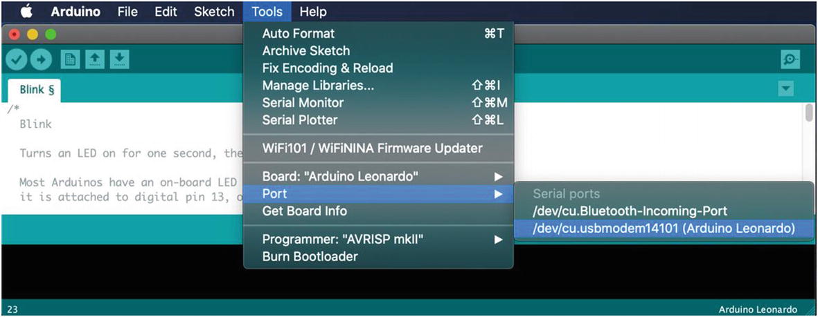
Choosing the serial port
See www.arduino.cc/en/Guide/HomePage?from=Guide.Howto if you need help installing the drivers on Windows.
OK, now that you have your Arduino IDE installed, you can connect your Arduino and set the board and serial port. You see the LEDs on the Arduino illuminate. This is because the Arduino is getting power from the USB. Thus, you do not need to provide an external power supply when the Arduino is connected to your computer. Next, you dive into a simple project to demonstrate the Arduino IDE and learn how basic sketches are built, compiled, and uploaded.
Project: Hardware “Hello, World!”
The ubiquitous “Hello, World!” project for the Arduino is the blinking light. The project uses an LED, a breadboard, and some jumper wires. The Arduino turns on and off through the course of the loop() iteration . That’s a fine project for getting started, but it does not relate to how sensors could be used.
Thus, in this section, you expand on the blinking light project by adding a sensor. In this case, you still keep things simple by using what is arguably the most basic of sensors: a pushbutton. The goal is to illuminate the LED whenever the button is pushed.
Hardware Connections

Diagram of an LED with a pushbutton
You’re almost there. Now wire a jumper from the power rail to one side of the pushbutton, and wire the other side of the pushbutton to (DIGITAL) pin 2 on the Arduino (located on the side with the USB connector). Next, wire the LED to ground on the breadboard and a 150 Ohm resistor (colors: brown, green, brown, gold). The other side of the resistor should be wired to pin 13 on the Arduino. You also need a resistor to pull the button low when the button is not pressed. Place a 10K Ohm resistor (colors: brown, black, orange, gold) on the side of the button with the wire to pin 2 and ground.
The longest side of the LED is the positive side. The positive side should be the one connected to the resistor. It doesn’t matter which direction you connect the resistor; it is used to limit the current to the LED. Check the drawing again to ensure that you have a similar setup.
Most Arduino boards have an LED connected to pin 13. You reuse the pin to demonstrate how to use analog output. Thus, you may see a small LED near pin 13 illuminate at the same time as the LED on the breadboard.
One of the coolest gadgets for working with the Arduino is the Arduino mounting plate from Adafruit (www.adafruit.com/products/275).

Although you can make your own Arduino mounting plate from Lexan or Plexiglas (I have), the Adafruit product is just a notch better than what you can make yourself. For about US$5.00, you can keep your Arduino and breadboard together and avoid scratches on your table (from the sharp prongs on the bottom of the Arduino)—and, better still, avoid the nasty side effects of accidentally placing a powered Arduino on a conductive surface (never a good idea).
Writing the Sketch
The sketch you need for this project uses two I/O pins on the Arduino: one output and one input. The output pin will be used to illuminate the LED, and the input pin will detect the pushbutton engagement. You connect positive voltage to one side of the pushbutton and the other side to the input pin. When you detect voltage on the input pin, you tell the Arduino processor to send positive voltage to the output pin. In this case, the positive side of the LED is connected to the output pin.
In the loop() method, you place code to detect the button press. Use the digitalRead() method to read the status of the pin (LOW or HIGH), where LOW means there is no voltage on the pin and HIGH means positive voltage is detected on the pin.
Simple Sensor Sketch
When you’ve entered the sketch as written, you are ready to compile and run it. Name the sketch basic_sensor.ino.
Want to avoid typing all this by hand? You can find the source code on the Apress site for this book.
Compiling and Uploading
Once you have the sketch written, test the compilation using the Compile button in the upper-left corner of the IDE. Fix any compilation errors that appear in the message window. Typical errors include misspellings or case changes (the compiler is case sensitive) for variables or methods.
After you have fixed any compilation errors, click the Upload button. The IDE compiles the sketch and uploads the compiled sketch to the Arduino board. You can track the progress via the progress bar at lower right, above the message window. When the compiled sketch is uploaded, the progress bar disappears.
Testing the Sensor
Once the upload is complete, what do you see on your Arduino? If you’ve done everything right, the answer is nothing. It’s just staring back at you with that one dark LED—almost mockingly. Now, press the pushbutton. Did the LED illuminate? If so, congratulations: you’re an Arduino programmer!
If the LED did not illuminate, hold the button down for a second or two. If that does not work, check all of your connections to make sure you are plugged in to the correct runs on the breadboard and that your LED is properly seated with the longer leg connected to the resistor, which is connected to pin 13.
On the other hand, if the LED stays illuminated, try reorienting your pushbutton 90 degrees. You may have set the pushbutton in the wrong orientation.
Try out the project a few times until the elation passes. If you’re an old hand at Arduino, that may be a very short period. If this is all new to you, go ahead and push that button and bask in the glory of having built your first sensor node!
The next section examines a more complicated sensor node, using a temperature and humidity sensor that sends digital data. As you will see, there is a lot more to do.
Hosting Sensors with Arduino
The digital and analog pins of the Arduino make it an ideal platform for hosting sensors. Since most sensors need very little in the way of supporting components, you can often host multiple sensors on one Arduino. For example, it is possible to host a temperature sensor or even multiple temperature sensors, barometric, humidity, and so on, for sampling weather conditions from a given site.
SparkFun and Adafruit have excellent websites that provide a great deal of information about the products they sell. Often the sensor product page includes links to examples and more information about using the sensor. If you are new to electronics, you should stick to sensors that provide examples of their use. It may sound like cheating, but unless you have a good knowledge of electronics, using a sensor incorrectly can get expensive as you burn your way through a few destroyed components before you get it right.
However, when there is another sensor you want to use, you should examine its datasheet. Most manufacturers and vendors supply the datasheet via a link on the product page. The datasheet provides all the information you need to use the sensor but may not have an actual example of its use. If you are familiar with electronics, this is all you are likely to need.
If you are more of a hobbyist or novice at electronics, check the wikis and forums on Arduino.cc, SparkFun, and Adafruit. These sites have a wealth of information and a great many examples, complete with sample code. If you cannot find any examples, you can try googling for one. Use terms like “Arduino <sensor name> example”. If you cannot find any examples and are not an experienced electronics technician, you might want to reconsider using the sensor.
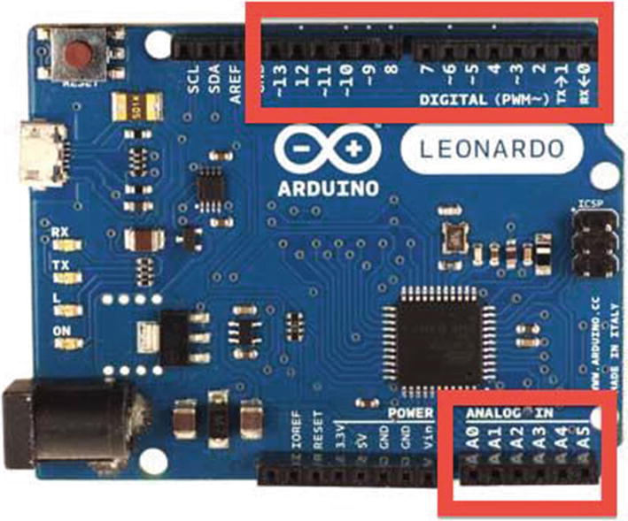
Identifying the I/O pins on an Arduino board
Now let’s put the knowledge you’ve gained from learning about the Arduino to use in building a sensor node with an Arduino and a sensor.
Project: Building an Arduino Temperature Sensor
In this project, you build a more sophisticated Arduino-hosted sensor node. This project not only demonstrates how to host sensors with an Arduino but also provides an example of why you need a microcontroller to host certain types of sensors. In this case, the DHT22 sensor is a digital sensor that has its own protocol, which requires a bit of logic to interpret correctly, thereby making it more complicated to use with an XBee.2 Later, you see an example of a simple analog sensor that you can connect directly to an XBee module.
This project uses a DHT22 temperature and humidity sensor connected to the Arduino via a breadboard. The DHT22 is a simple digital sensor that produces digital signals. It requires a single resistor to pull up from the data pin to voltage. Pull-up in this case makes sure the data value is “pulled up” to the voltage level to ensure a valid logic level on the wire.
Let’s jump right in and connect the hardware.
This example was adapted from an example on the Adafruit website (http://learn.adafruit.com/dht).
Hardware Setup
The hardware required for this project includes an Arduino, a DHT22 humidity and temperature sensor, a breadboard, a 4.7K Ohm resistor (colors: yellow, purple, red, gold), and breadboard jumper wires.
If you get stuck or want more information, there is an excellent tutorial on Adafruit’s website.
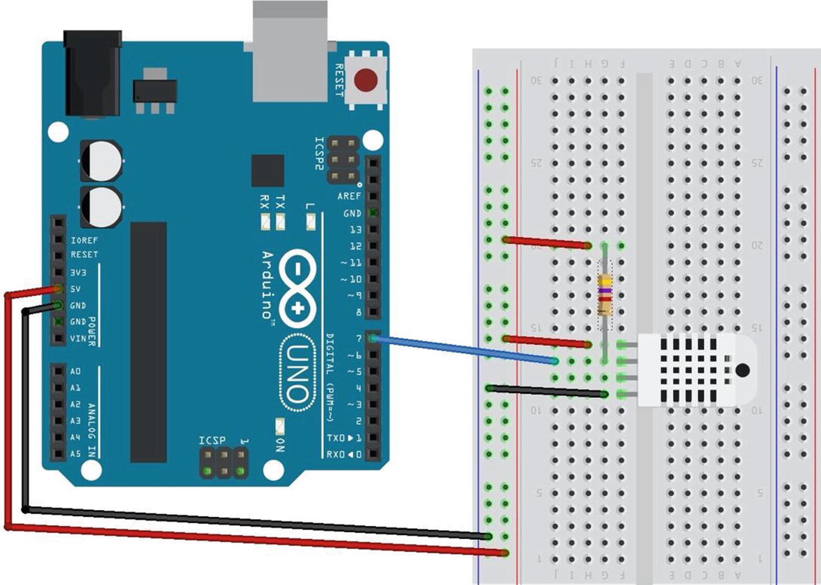
Wiring the DHT22
DHT22 Connections
Pin | Connected To |
|---|---|
1 | +5V, 4.7K resistor between the power supply and the data pin (strong pull-up) |
2 | Pin 7 on Arduino, 4.7K resistor |
3 | No connection |
4 | Ground |
Next, connect the ground and power of the sensor to the breadboard power and ground rails. Then connect one wire from the data pin on the sensor to pin 7 of the Arduino. There is one last connection: you use a pull-up resistor of 4.7K Ohm connected to the data wire and the power rail of the breadboard.
Software Setup

Library manager
It may take a moment for the library manager to connect to the server and download the latest catalog. When it is complete, you can type DHT22 into the text box in the upper right and press ENTER. This will search the library catalog for all of the libraries that match.
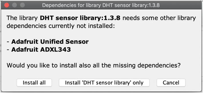
Install all libraries
Now that you have the hardware configured and the DHT22 library set up, let’s write some code!
Writing the Sketch
Data Methods from DHT Library
Method | Description |
|---|---|
dht.readHumidity() | Read the humidity |
dht.readTemperature() | Read temperature in Celsius |
dht.readTemperature(true) | Read temperature in Fahrenheit |
dht.computeHeatIndex(temp_c, humidity, false) | Get heat index in Celsius |
dht.computeHeatIndex(temp_c, humidity, true) | Get heat index in Fahrenheit |
The read_data() Method
Notice the code is pretty simple. We just read the values and then use the Serial.print() and Serial.println() methods to write the data to the serial monitor.
Completed Sketch: Reading a DHT-22 Sensor
If you have not done so already, open a new Arduino sketch by clicking the New menu button or by choosing File ➤ New. Now you can compile, upload, and test the project. You can name it whatever you like such as dht22_example.ino.
Test Execution
Executing the sketch means uploading it to your Arduino and watching it run. If you haven’t connected your Arduino, you can do that now.
I like to begin by compiling the sketch. Click the check mark on the left side of the Arduino application, and observe the output in the message screen at the bottom. If you see errors, fix them and retry the compile. Common errors include missing the DHT22 library (which may require restarting the Arduino application), typing errors, syntax errors, and the like. Once everything compiles correctly, you are ready to upload your sketch by clicking the Upload button on the toolbar.
Output of the DHT22 Sensor Sketch
If you see similar output, congratulations! You have just built your first Arduino-hosted sensor node. This is an important step in building your sensor network, as you now have the tools needed to start building more sophisticated, wireless sensor nodes and aggregate nodes for recording sensor data.
Let’s take the Arduino sensor experience one step further and add XBee modules to enable the sensor to be placed away from the Arduino. This effectively demonstrates how an Arduino can remotely host a number of sensor nodes and thus become an aggregate node in a sensor network.
Project: Using an Arduino As a Data Collector for XBee Sensor Nodes
This project combines what you have learned about the Arduino in this chapter and the XBee in Chapters 2 and 4. More specifically, you use an Arduino and a remote sensor that connects the sensor with the Arduino using XBee modules. We will reuse the XBee sensor node from Chapter 4 and use the Arduino to read the data.
XBee Sensor Node
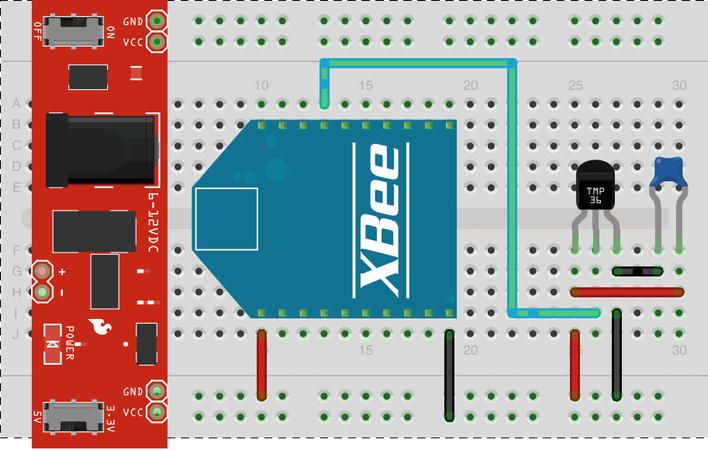
XBee sensor node
XBee Sensor Node Options and Values
Code | Setting Name | Description | Value |
|---|---|---|---|
D3 | AD3/DIO3 | Trigger analog or digital data recording | 2—ADC |
ID | PAN ID | Id for the network | 8088 |
IR | I/O Sampling Rate | Time to wait to send data | 3A98—15,000ms |
NI | Node Identifier | Name for the node | TMP36 |
V+ | Supply Voltage Threshold | Supply voltage | FFFF (always send) |
Notice unlike the project from Chapter 5, we must set up the I/O sampling rate. This is because the library we will be using does not have the same ability to search the ZigBee network for our remote node. Rather, in this project, the Arduino will poll until an IO sample is delivered to the coordinator node. Thus, we have seen two different ways to get data from a ZigBee network—requesting data directly from a node (Chapter 5) and polling for data sent from nodes (this chapter).
Coordinator Node
XBee Coordinator Options and Values
Code | Setting Name | Description | Value |
|---|---|---|---|
ID | PAN ID | Id for the network | 8088 |
NI | Node Identifier | Name for the node | Coordinator |
There is no need to install the XBee module just yet. You need to configure its settings. You do that in the next section.
Now, let’s set up the Arduino and XBee.
Arduino with XBee Shield
You can use an Arduino to read the data from the XBee sensor node. This gives you an example of using an Arduino as a data aggregator (collector) of sensor data from XBee sensor nodes. Let’s set up an Arduino with an XBee. This project demonstrates using an Arduino to receive data via XBee, but you can also send data via XBee.
Hardware Setup

Arduino XBee shield (courtesy of SparkFun)
I use this shield to demonstrate how to communicate with an XBee module. If you decide to use another shield, be sure to check that shield’s documentation for examples of how to use it and compare it with the code in this project. Make the appropriate modifications (hardware connections and changes to the sketch) so that your project will work correctly with your shield.
The shield lets you choose to communicate with the Arduino with the onboard serial circuitry (UART3) for the Arduino via digital pins 0 and 1. But these are also the pins used when communicating with the Arduino via USB from the Arduino IDE. Fortunately, the SparkFun XBee shield has a small switch that allows you to choose to use pins 2 and 3 instead. You use this option so that you can write a script to read data from the shield via the XBee and still connect to the Arduino IDE and use the serial monitor. But there is a catch: only one UART is available. You must use the software serial library to simulate a second serial connection. The software serial library is included in the Arduino IDE. You see how to do this in the “Software Setup” section.
If you are using a different XBee shield, you should consult the documentation on the shield and use the pins as instructed. Some shields are hard wired.
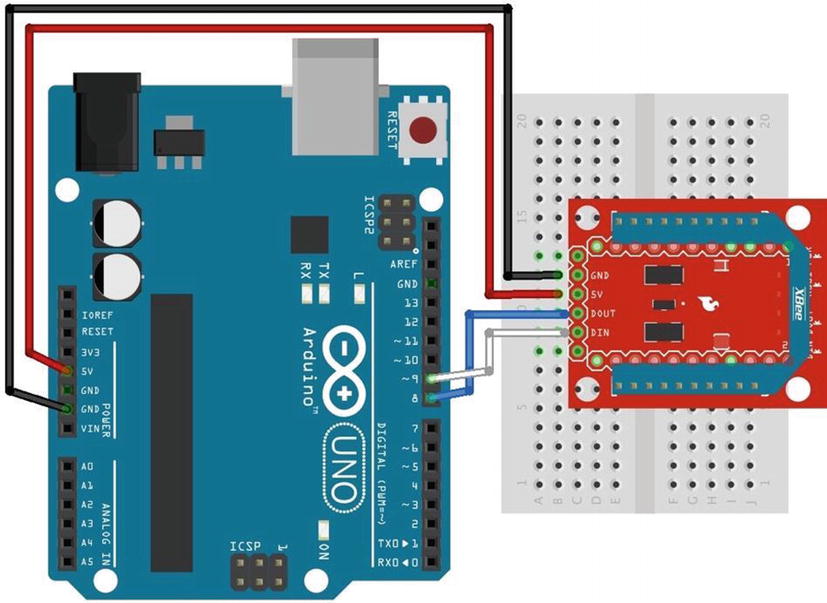
Connecting an XBee to an Arduino via a SparkFun XBee breakout board
Either of these methods will work for this project.
Whichever method you choose, take the XBee coordinator module off your USB adapter and insert it into the XBee shield or the XBee Explorer Regulated breakout board. Now that the hardware is ready, let’s set up your Arduino environment and write a sketch to read the data from the XBee sensor node.
Software Setup
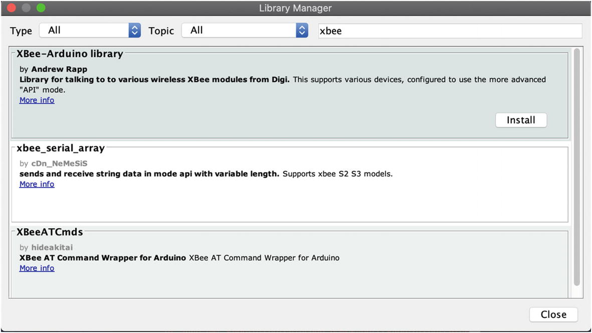
Loading the XBee Arduino library
Once the library is installed and you have restarted your Arduino IDE, you can write the script to read the data from the XBee. The library has classes for each of the popular XBee data packets to send and receive data to or from an XBee. This project uses the IO sample class because you know that is the only packet we are interested in using in this project.
You need to create several parts of the sketch. Using the XBee library is easier than writing your own communication methods, but the library has certain setup steps and methods you need to use to read the data packet.
Notice the line with the while loop. You need to add this for use on Leonardo boards. If you omit this and run the sketch on a Leonardo board, the XBee may fail to work. Add this loop to allow the Leonardo time to start the Serial instance.
Notice that you simply use the ioSample class instance and call the method getRemoteAddress64().getMsb(). Actually, this is a call to a subclass (RemoteAddress64) and its method getMsb(). This returns the most significant byte (high 16 bits) of the 64-bit address. You do the same for the least significant bit with the getRemoteAddress64().getLsb() call. You then print these values, specifying that you want to print them in hexadecimal. If you were reading data from multiple XBee nodes, it would be handy to apply a name to each address, such as “bedroom” or “living room”. I leave that to you as an exercise.
Finally, you need to read the supply voltage from the data packet. In this case, the supply voltage appears after the data samples. Because you know there is only one data sample (via the analog sample mask), you know that the analog voltage appears right before the checksum. Sadly, there is no method currently to fetch that information from the I/O sample packet in the XBee library. However, all is not lost, because the author of the library stores the data in an array and has supplied a subclass for you to use to fetch the raw data. In this case, you want bytes 17 (most significant byte) and 18 (least significant byte) from the data. You know these are the indexes needed by counting from the byte following the frame type starting from zero. See Table 6-5 for details.
Take some time to examine the calculations. In this example, you convert the voltage read and sent by the XBee sensor node to Celsius and then again to Fahrenheit. You also convert the supply voltage to volts for easier reading. All these values are sent to the serial monitor for feedback during testing.
Once you have those methods implemented, you place the code to read the data from the XBee in the loop() method, calling these methods to decipher the data and print it to the serial monitor.
Notice that in the code you check to see whether the packet is available; if it is, you read it. If the packet read is the right frame type, in this case ZB_IO_SAMPLE_RESPONSE, you read the data from the packet and display it. If it isn’t the right packet, you print out to the serial monitor the frame type of the packet received. If there is an error reading the packet, you capture that in the last else and display the error to the serial monitor.
Notice the contents of the block of code for the ZB_IO_SAMPLE_RESPONSE condition. You begin by initializing the I/O data sample class with the data read, then read the address of the XBee that sent the packet, and then perform the calculations for temperature and reference voltage.
Arduino XBee Receiver
Take some time to ensure that the sketch compiles before you upload it to your Arduino. Remember, once the sketch is uploaded, it begins to run. Save it as xbee_sensor.ino.
Testing the Final Project
Sample Output of the XBee Arduino Sketch
Did you see something similar? If so, you’re doing great work and now have the rudimentary components to build sensor nodes and Arduino-based sensor data aggregators.
If you do not see any output in the serial monitor, do not panic. Instead, double-check that the XBee on your Arduino is plugged in correctly and that you are using the correct pins in the sketch that correspond to how the XBee shield you are using connects to the Arduino (not all shields use pins 2 and 3 like the SparkFun shield). Hint: Check the documentation for your shield.
If all that is correct, make sure you are using the coordinator API firmware on the XBee connected to the Arduino and the router API firmware on the XBee sensor node. If you are still having issues, step back to the previous project to ensure that the sensor node is still working.
You can also try turning off both the Arduino and the XBee sensor node; then turn on the Arduino, wait about 10 seconds, and turn the XBee sensor node back on. Sometimes the handshake process and network join can stall, and nothing happens for a while. Turning an XBee off and back on in this order ensures that it will reattempt to configure.
On the other hand, maybe you are getting data, but it is not correct—the temperature read is far too low for the actual environment. I had this happen once when the wire I was using to connect to the data pin on the TMP36 was accidentally removed. The bottom line is always check and recheck your wiring.
For More Fun
If you would like to expand the project, you can add a second XBee sensor node and modify the Arduino sketch to supply a location for each node. For example, you could label one node “office” and the other “kitchen”. The sketch should record (write to the serial monitor) the location of the sensor along with the sensor data from the XBee.
Component Shopping List
Components Needed
Item | Vendors | Est. Cost USD | Qty Needed |
|---|---|---|---|
LED (any color) | $0.35 | 1 | |
Pushbutton (breadboard mount) | $0.35 | 1 | |
Breadboard (not mini) | $5.95 | 1 | |
Breadboard jumper wires | $3.95 | 1 | |
DHT22 | $9.95 | 1 | |
150 Ohm resistor | Most online and retail stores | Varies | 1 |
4.7K Ohm resistor | Most online and retail stores | Varies | 1 |
10K Ohm resistor | Most online and retail stores | Varies | 1 |
Arduino XBee shield | $24.95 | 1 | |
XBee-ZB (ZB) series 2, 2.5, or 3 | $25.00+ | 2 | |
TMP36 sensor | $1.50 | 1 | |
Breadboard power supply | $14.95 | 1 | |
Wall power supply (6V–12V) | $5.95 | 1 | |
0.10mF capacitor | $0.25 | 1 | |
XBee Explorer Regulated with headers | $9.95 | 1 | |
Breakaway male headers (optional) | $4.95 | 1 | |
Arduino Uno (any that supports shields) | Various | $25.00 and up | 1 |
SparkFun XBee shield | $24.95 | 1 | |
Soldering iron and solder (optional) | Most online and retail stores | Varies | 1 |
Summary
This chapter covered a lot of ground. You explored the Arduino platform, including the many forms available and how to write sketches (programs) to control the Arduino. I also showed you how to host sensors with the Arduino by using a temperature and humidity sensor.
You applied the information you learned about the XBee in Chapters 2 and 4 to create an XBee sensor node to read temperature data. You then set up an Arduino with an XBee coordinator to receive the sensor data from the XBee sensor node and display it in the serial monitor.
In the next chapter, you will discover various mechanisms for storing sensor data either onboard or in the cloud.