
Using XBee modules and microcontrollers to host sensors is an economical way to build a sensor network. But what do you do when you need more computational power than a microcontroller can provide? What if you need to convert the data to a different format, incorporate the data in an application, or print a hard copy of the sensor data? In these situations, you likely need a computer that has more processing power, can allow the use of common applications, permits the use of scripting languages, and affords access to peripherals.
Although personal computers are relatively inexpensive, there are a few distinct disadvantages to using personal computers in your sensor networks—especially as sensor nodes. If the sensors are located in areas where mains power is unreliable or unavailable, or where there is a risk of overheating, or where there is simply no room to install a personal computer, you must either transmit the data to another node for processing or store it locally and process it later.
However, there is another limitation to using a personal computer as a sensor node: a personal computer has no general input/output (I/O) ports. You can purchase expansion cards for collecting data, but these are often built for use in server or desktop computers. If you consider the cost of the computer and the data-collection card, the cost of the sensor node becomes uneconomical.
So, what do you do in these cases? If only there were a low-cost computer with sufficient processing power and memory that used standard peripherals, supported programmable I/O ports,1 and had a small form factor. That’s exactly what the Raspberry Pi can do.
This chapter explores getting started with the Raspberry Pi, including how to use the system and how to read sensors using the I/O ports. You also explore a few types of sensors and examine the differences in how you read data from them.
We will cover both the Raspberry Pi 3B and the newest Raspberry Pi 4B. You can use either for the projects in this book, but most figures depict the Raspberry Pi 3B and 3B+. Fortunately, all GPIO connections are the same on 3B, 3B+, and 4B boards.
What Is a Raspberry Pi?
The Raspberry Pi is a small, inexpensive personal computer. Although it lacks the capacity for RAM (random access memory) expansion and it doesn’t have onboard devices such as CD, DVD, and hard drives,2 it has everything a simple personal computer requires. That is, it has four USB ports (the Raspberry Pi 3 has 2.0 ports, the Raspberry Pi 4B has two USB 2.0 and two USB 3 ports), an Ethernet port, HDMI video, and even an audio connector for sound.
The Raspberry Pi has an SD drive3 that you can use to boot the computer into any of several Linux operating systems. All you need is an HDMI cable and monitor (or DVI cable and monitor with an HDMI to DVI adapter), a USB keyboard and mouse, and a 5V power supply, and you’re off and running.
As of this writing, it is not possible to boot from a USB drive on the Raspberry Pi 4B. Blogs suggest this feature will be available soon. When it becomes available, you can easily create a faster boot system by moving the operating system to a USB drive.
You can also power your Raspberry Pi using a USB port on your computer. In this case, you need a USB type A male to micro-USB type B male cable (Raspberry Pi 3B) or a USB type A male to USB-C male cable. Plug the type A side into a USB port on your computer and the micro-USB type B/USB-C side into the Raspberry Pi power port.
The board is available in several versions and comes as a bare board costing as little as $35.00. The newer Raspberry Pi 4B comes in 1GB, 2GB, 4GB, or 8GB variants (only the memory differs) ranging in price from $35.00 to $65.00. It can be purchased online from electronics vendors such as SparkFun and Adafruit. Some Best Buy retailers have started carrying the Raspberry Pi 4B 2GB boards as well as the basic accessories (e.g., case, power supply). Most online vendors have a host of accessories that have been tested and verified to work with the Raspberry Pi. These include small monitors, miniature keyboards, and even cases for mounting the board.
In this section, you explore the origins of the Raspberry Pi, take a tour of the hardware connections, and discover what accessories are needed to get started using the Raspberry Pi.
Noble Origins
The Raspberry Pi was designed to be a platform to explore topics in computer science. The designers saw the need to provide inexpensive, accessible computers that could be programmed to interact with hardware such as servo motors, display devices, and sensors. They also wanted to break the mold of having to spend hundreds of dollars on a personal computer and thus make computers available to a much wider audience.
The designers observed a decline in the experience of students entering computer science curriculums. Instead of having some experience in programming or hardware, students are entering their academic years having little or no experience with working with computer systems, hardware, or programming. Rather, students are well versed in Internet technologies and applications. One of the contributing factors cited is the higher cost and greater sophistication of the personal computer, which means parents are reluctant to let their children experiment on the family PC.
This poses a challenge to academic institutions, which have to adjust their curriculums to make computer science palatable to students. They have had to abandon lower-level hardware and software topics due to students’ lack of interest or ability. Students no longer wish to study the fundamentals of computer science such as assembly language, operating systems, theory of computation, and concurrent programming. Rather, they want to learn higher-level languages to develop applications and web services. Thus, some academic institutions are no longer offering courses in fundamental computer science.4 This could lead to a loss of knowledge and skill sets in future generations of computer professionals.
To combat this trend, the designers of the Raspberry Pi felt that, equipped with the right platform, youth could return to experimenting with personal computers as in the days when PCs required a much greater commitment to learning the system and programming it in order to meet your needs. For example, the venerable Commodore 64, Amiga, and early Apple and IBM PC computers had very limited software offerings. Having owned a number of these machines, I was exposed to the wonder and discovery of programming at an early age.5
The name was partly derived from design committee contributions and partly chosen to continue a tradition of naming new computing platforms after fruit (think about it). The Pi portion comes from Python, because the designers intended Python to be the language of choice for programming the computer. However, other programming language choices are available.
The Raspberry Pi is an attempt to provide an inexpensive platform that encourages experimentation. The following sections explore more about the Raspberry Pi, including the models available, required accessories, and where to buy the boards.
Models
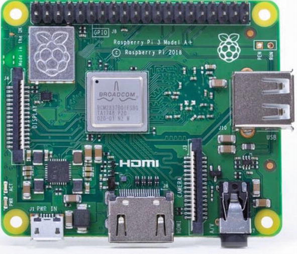
Raspberry Pi 3A+ (courtesy of the Raspberry Pi Foundation)
The “+” symbol in the model designation indicates it is a newer release of the same version only with some improvements. For example, the 3B+ included a slightly faster processor and a host of minor refinements. Typically, the boards are effectively the same and you may not notice a difference, but if you want the “latest” or “better” board, you’ll want the one with the “+” designation.

Raspberry Pi 3B+ (courtesy of the Raspberry Pi Foundation)
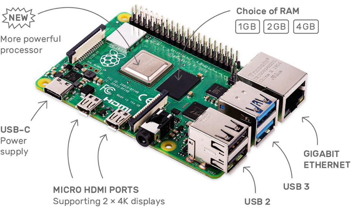
Raspberry Pi 4B (courtesy of the Raspberry Pi Foundation)
You can often find the Raspberry Pi 3A+ at online retailers and auction sites for a bit less than the Raspberry Pi 3B+ board. The newest Raspberry Pi 4B are still in high demand so you may pay more for those boards but shop around to find retailers that offer the board at suggested retail prices of $35 (1GB), $45 (2GB), $55 (4GB), or $91 (8GB). If you plan to use the Raspberry Pi for experimentation and do not need the extra memory to run memory-intensive applications, you can use the Raspberry Pi 3A+.
It is recommended to use the Raspberry Pi 3B+ or the newest, the Raspberry 4B, for the projects in this book. The examples in this chapter and the remaining chapters use the Model B variant—either the Raspberry Pi 3B+ or 4B.
A Tour of the Board
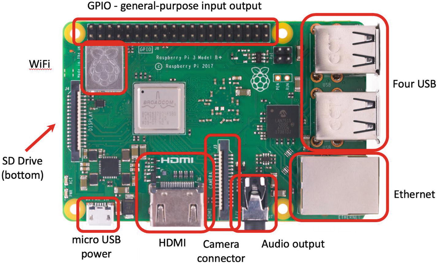
Raspberry Pi 3B+ (courtesy of the Raspberry Pi Foundation)
In the center of the near side, you see an HDMI connector. To the left of the HDMI connector is the micro-USB power connector and to the right is the camera connector and audio connector. The power connector is known to be a bit fragile on some boards, so take care plugging and unplugging it. Be sure to avoid putting extra strain on this cable while using your Raspberry Pi.
On the left side of the board, we see the location of the WiFi chip. On the underside of the board is where the microSD card connector is located. Interestingly, most cases are not designed to protect the microSD card. When installed, the microSD card protrudes a few centimeters out of the board.
On the far side of the board is the general-purpose input/output (GPIO) header (a double row of 20 pins), which can be used to attach to sensors and other devices. You will work with this connector later in this chapter.
On the right side of the board are four USB connectors and the Ethernet connector. An external powered USB hub connected to the USB ports on the Raspberry Pi can power some boards, but it is recommended that you use a dedicated power supply connected to the micro-USB connector.
Because the board is small, it is tempting to use it in precarious places like in a moving vehicle or on a messy desk. Ensure that your Raspberry Pi is in a secure location. The micro-USB power and microSD card slots seem to the most vulnerable to damage.6
Take a moment to examine the top and bottom faces of the board. As you can see, components are mounted on both sides. This is a departure from most boards that have components on only one side. The primary reason the Raspberry Pi has components on both sides is that it uses multiple layers for trace runs. This permits the board to be much smaller and enables the use of both surfaces for mounting its components. This is probably the most compelling reason to consider using a case—to protect the components on the bottom of the board and thus avoid shorts and board failure.
Required Accessories
The Raspberry Pi is sold as a bare system board with no case, power supply, or peripherals. Depending on how you plan to use the Raspberry Pi, you need a few commonly available accessories. If you have been accumulating spares like me, a quick rummage through your stores may locate most of what you need.
If you want to use the Raspberry Pi in console mode (no graphical user interface), you need a USB power supply (USB-C for the Raspberry Pi 4B), a keyboard, and an HDMI cable and monitor. The power supply should have a minimal rating of 2500mA or greater for the Raspberry Pi 3B, 3B+ boards, and 3000mA USB-C (15 Watt) or greater for the Raspberry Pi 4B. If you want to use the Raspberry Pi with a graphical user interface, you also need a mouse.
If you have to purchase these items, stick to the commonly available brands and models without extra features. For example, avoid the latest multifunction keyboard and mouse. Chances are they require drivers that are not available for the various operating system choices for the Raspberry Pi.
You also must have a microSD card. I recommend a 16GB or higher version. Recall that the microSD is the only onboard storage medium available. You will need to put the operating system on the card, and any files you create will be stored on the card.
If you want to use sound in your applications, you also need a set of powered speakers that accept a standard 3.5mm audio jack. Finally, if you want to connect your Raspberry Pi to the Internet, you need access to a WiFi access port or an Ethernet hub.
Recommended Accessories
I highly recommend at least adding small rubber or silicone self-adhesive bumpers to keep the board off your desk. On the bottom of the board are many sharp prongs that can come into contact with conductive materials, which can lead to shorts or, worse, a blown Raspberry Pi. These bumpers are available at most home-improvement and hardware stores.
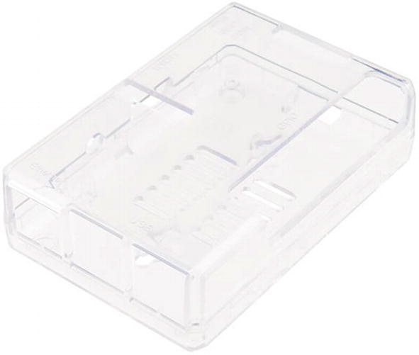
If you plan to move the board from room to room or you want to ensure that your Raspberry Pi is well protected against accidental damage, you should consider purchasing a case to house the board. Many cases are available, ranging from simple snap-together models to models made from laser-cut acrylic or even milled aluminum. The following list includes several excellent choices, complete with vendor links.
Pi Tin
Pi Tin (courtesy of SparkFun)
Aluminum Heatsink Case for Raspberry Pi 4B

Aluminum Heatsink Case for Raspberry Pi 4B (courtesy of SparkFun)
Pibow Coupé
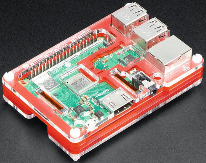
Pibow Coupé (courtesy of Adafruit)
If none of these cases meet your needs or aesthetic choices, you can find a host of options from Adafruit at www.adafruit.com/category/395. You’re sure to find what you want there!
Aside from a case, you should also consider purchasing (or pulling from your spares) a powered USB hub. The USB hub power module should be 2500mA or more (some suggest you need only a 1500mA, but more is better especially if you want to connect USB devices to your board). A powered hub is required if you plan to use USB devices that draw a lot of power, such as a USB hard drive or a USB soft missile launcher.
Where to Buy
SparkFun (www.sparkfun.com/categories/233)
Adafruit (www.adafruit.com/category/105)
PiShop.us (www.pishop.us)
The PiHut (ships internationally) (www.thepihut.com)
The next section presents a short tutorial on getting started using the Raspberry Pi. If you have already learned how to use the Raspberry Pi, you can skip to the following section to begin learning how to connect sensors to your board.
Raspberry Pi Tutorial
The Raspberry Pi is a personal computer with a surprising amount of power and versatility. You may be tempted to consider it a toy or a severely limited platform, but that is far from the truth. With the addition of onboard peripherals like USB, WiFi, Ethernet, and HDMI video, the Raspberry Pi has everything you need for a lightweight desktop computer. This is especially true for the Raspberry Pi 4B with 2GB or 4GB or 8GB of RAM—those make nice desktop computers!
Furthermore, if you consider the addition of the GPIO header, the Raspberry Pi becomes more than a simple desktop computer and fulfills its role as a computing system designed to promote hardware experimentation.
The following sections present a short tutorial on getting started with your new Raspberry Pi, from a bare board to a fully operational platform. A number of excellent works cover this topic in much greater detail. If you find yourself stuck or wanting to know more about beginning to use the Raspberry Pi and more about the Raspbian operating system, see Computing with the Raspberry Pi by B. Schell (Apress, 2019). If you want to know more about using the Raspberry Pi in hardware projects, an excellent in-depth resource is Advanced Raspberry Pi by W. Gay (Apress, 2018).
Getting Started
As mentioned in the “Required Accessories” section, you need a microSD card (16GB is recommended), a USB power supply rated at 2500mA or better with a male micro-USB connector (or USB-C for Raspberry Pi 4B), a keyboard, a mouse (optional), and an HDMI cable and monitor or a DVI monitor with an HDMI adapter. However, before you can plug these things in to your Raspberry Pi and bask in its brilliance, you need to create a boot image for your microSD card.
Installing a Boot Image
The process of installing a boot image involves choosing an image, downloading it, and then copying it to your microSD (hence simply SD) card. The following sections detail the steps involved.
Choosing the Image
Raspbian Buster : The basic or default image. It is based on Debian and contains a graphical user interface, development tools, and rudimentary multimedia features.
Ubuntu MATE: Provides a complete, familiar (if you know Ubuntu), desktop environment for basic desktop computing.
Ubuntu Core: A hardened Ubuntu core operating system for uses where security is of great importance.
Ubuntu Server: A scaled down version of the Ubuntu server for running server applications.
If you are just starting with the Raspberry Pi, you should use the Raspbian image. This image is also recommended for the examples in this book.
There are two ways to go about making an image for your Raspberry Pi. The easiest way is to use a special boot loaded called New Out Of the Box Software (NOOBS) , which is used to help streamline the setup of your board. The other is to download a specific image and format the SD card with the image. I will show you both methods in the following sections.
Installing Using NOOBS
This is by far the easiest method to build your SD card. All you need to do is download and unzip NOOBS from www.raspberrypi.org/downloads/noobs/, format an SD card, and then copy the files. Once you boot from NOOBS, you will be guided to install the default operating system (Raspbian) or another of your choice (requires additional downloads).
There are some excellent resources for learning how to install Raspbian with NOOBS. There is a nice video at www.raspberrypi.org/help/videos/#noobs-setup.
- 1.
Download the NOOBS binary from www.raspberrypi.org/downloads/noobs/. There are two options: a smaller one that will use the Internet to download during the install and a larger one that has the Raspbian image. If you have a slow Internet connection or cannot connect your Raspberry Pi to the Internet during install, you should choose the version with Raspbian (not the Lite one). This is a Zip file that you can download and unzip.
- 2.
You must format the SD card. For best results, use a 16GB or 32GB card. You can use any application you want, but the best I’ve found is to download SD Formatter from www.sdcard.org/downloads/formatter/index.html, which is available for most platforms.
- 3.
Next, locate the files from the NOOBS archive that you unzipped earlier and copy all of them to the SD card.
- 4.
Insert the SD card into your Raspberry Pi; connect your mouse, keyboard, and monitor; and power it on.
- 5.
Follow the onscreen instructions to install Raspbian.
That’s it! Once again, the online tutorial and videos are much more detailed, but now that you have a sense of the process, following the online tutorial will be very easy.
Installing Raspbian
If you want to install Raspbian to the SD card or don’t want to use NOOBS, you can download Raspbian from www.raspberrypi.org/downloads/raspbian/. For this book, you should choose the one named “Raspbian Buster with desktop and recommended software”. Unlike the NOOBS option, this file is a bootable image file that requires a special process to build a new bootable image on your SD card.
See www.raspberrypi.org/documentation/installation/installing-images/README.md for a tutorial on installing images for the Raspberry Pi.
Once you have downloaded the image, you first unzip the file and then transfer (sometimes called “write”) the image to your SD card. There are a variety of ways to do this. The following sections describe some simplified methods for a variety of platforms. You must have an SD card reader/writer connected to your computer. Some systems have SD card drives built in (Lenovo laptops, Apple laptops and desktops, and so on).
Windows
To create the SD card image on Windows, you can use the Win32 Disk Imager software from Launchpad (https://launchpad.net/win32-image-writer). Download this file, and install it on your system. Unzip the image if you haven’t already, and then insert your SD card into your SD card reader/writer. Launch the Win32 Disk Imager application, select the image in the top box, and then click WRITE to copy the image to the SD.
The copy process overwrites anything already on the SD card, so be sure to copy those photos to your hard drive first!
Mac OS X
To create the SD card image on the Mac, download the image and unzip it. Insert your SD card into your SD card reader/writer. Be sure the card is formatted with FAT32. Next, open the System report. (Hint: Use the Apple menu ➤ About This Mac.)
Click the card reader if you have a built-in card reader, or navigate through the USB menu and find the SD card. Take note of the disk number. For example, it could be disk4.
At this point, you should see the disk-drive indicator flash (if there is one), and you need to be patient. This step can run for some time with no user feedback. You will know it is complete when the command prompt is displayed again.
Linux
At this point, you should see the disk-drive indicator flash (if there is one), and you may need to be patient. This step can run for some time with no user feedback. You will know it is complete when the command prompt is displayed again.
Booting Up
To boot your Raspberry Pi, insert the SD card with the new image and plug in your peripherals. Wait to plug in the USB power last. Because the Raspberry Pi has no On/Off switch, it will start as soon as power is supplied. The following describes the process you will see and follow to boot Raspbian for the first time. The setup steps are executed only once (but you can change the settings later if you want).
When you power on the Raspberry Pi, the system bootstraps and then starts loading the OS. You see a long list of statements that communicate the status of each subsystem as it is loaded, followed by a welcome banner. You don’t have to try to read or even understand all the rows presented,7 but you should pay attention to any errors or warnings.
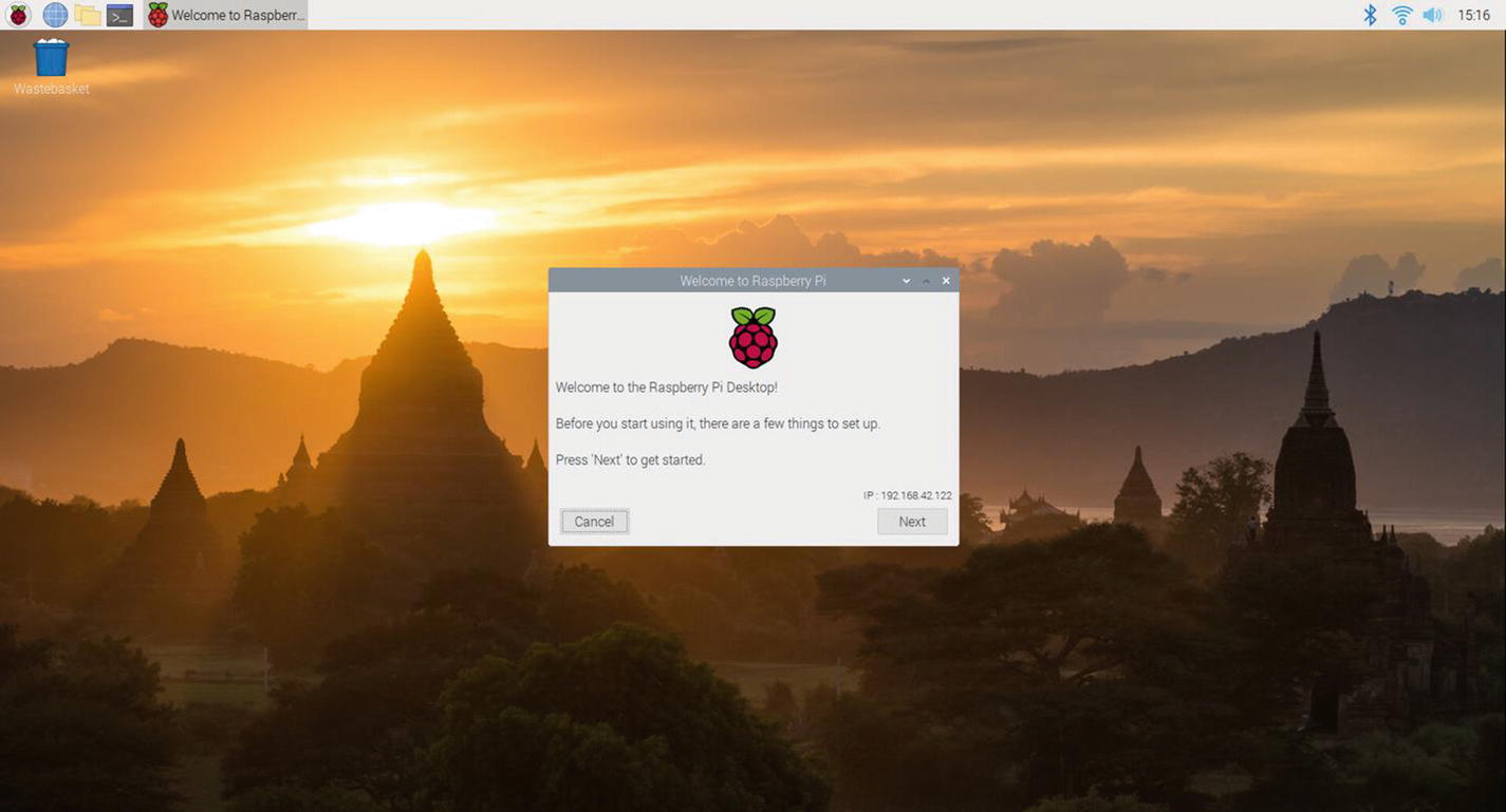
Raspbian desktop
Welcome to Raspberry Pi: Click Next to start the setup. You can cancel and run the setup later.
Set Country: Choose your country, language, and timezone. Click Next to continue.
Set Password: Choose the password for the default user. Click Next to continue.
Set Up Screen: If your screen shows a black rectangle around the edge, you can tick the checkbox to have the video adapter synchronize properly on the next boot. Click Next to continue.
Select WiFi Network: Choose your WiFi access point to connect to the Internet. You can click Skip to skip the step or click Next to continue.
Update Software: If you have connected to the Internet, you can optionally download and install updates for Raspbian. This is highly recommended, and when you choose this option, you will go through several more informational dialogs that show you the progress of the updates. You can click Skip to skip the step. Click Next to continue when done.
Setup Complete: The setup is done. Click Next to continue, and if you selected any options that require a reboot, the system will reboot now.
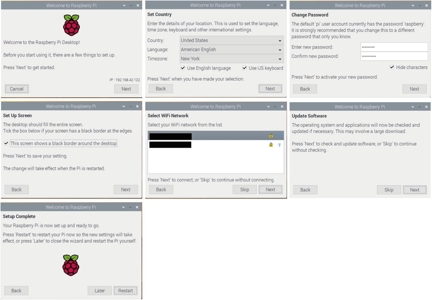
First boot setup sequence
When the system next boots, you will see the Raspbian desktop with your settings configured. If you set up a WiFi connection, it will automatically reconnect. Nice.
Care and Feeding of the SD Card
Imagine this scenario. You’re working away on creating files, downloading documents, and so on. Your productivity is high, and you’re enjoying your new low-cost, super-cool Raspberry Pi. Now imagine the power cable accidentally gets kicked out of the wall, and your Raspberry Pi loses power. No big deal, yes? Well, most of the time.
The SD card is not as robust as your hard drive. You may already know that it is unwise to power off a Linux system abruptly, because doing so can cause file corruption. Well, on the Raspberry Pi, it can cause a complete loss of your disk image. Symptoms range from minor read errors to inability to boot or load the image on bootstrap. This can happen—and there have been reports from others that it has happened more than once.
That is not to say all SD cards are bad or that the Raspberry Pi has issues. The corruption on accidental power-off is a side effect of the type of media. Some have reported that certain SD cards are more prone to this than others. The best thing you can do to protect yourself is to use an SD card that is known to work with Raspberry Pi and be sure to power the system down with the sudo shutdown -h now command—and never, ever power off the system in any other manner.
You can also make a backup of your SD card. See http://elinux.org/RPi_Beginners#Backup_your_SD_card for more details.
If you need any help at all when using your Raspberry Pi, there are very helpful articles at www.raspberrypi.org/help/, and the official documentation is at www.raspberrypi.org/documentation/.
GPIO Pin Mapping
The Raspberry Pi has a special hardware feature called the general-purpose I/O (GPIO) header. It is located in the upper-left portion of the board and resembles a floppy drive header.8 The header consists of two rows of 20 male pins.
All GPIO pins can be configured as either input (reading) or output (writing). The voltage read can be used for digital I/O. Specifically, when the voltage is less than 1.7V, the value is 0; greater than 1.7V is a value of 1. For output pins, you can set the voltage from 0 to 3.3V.
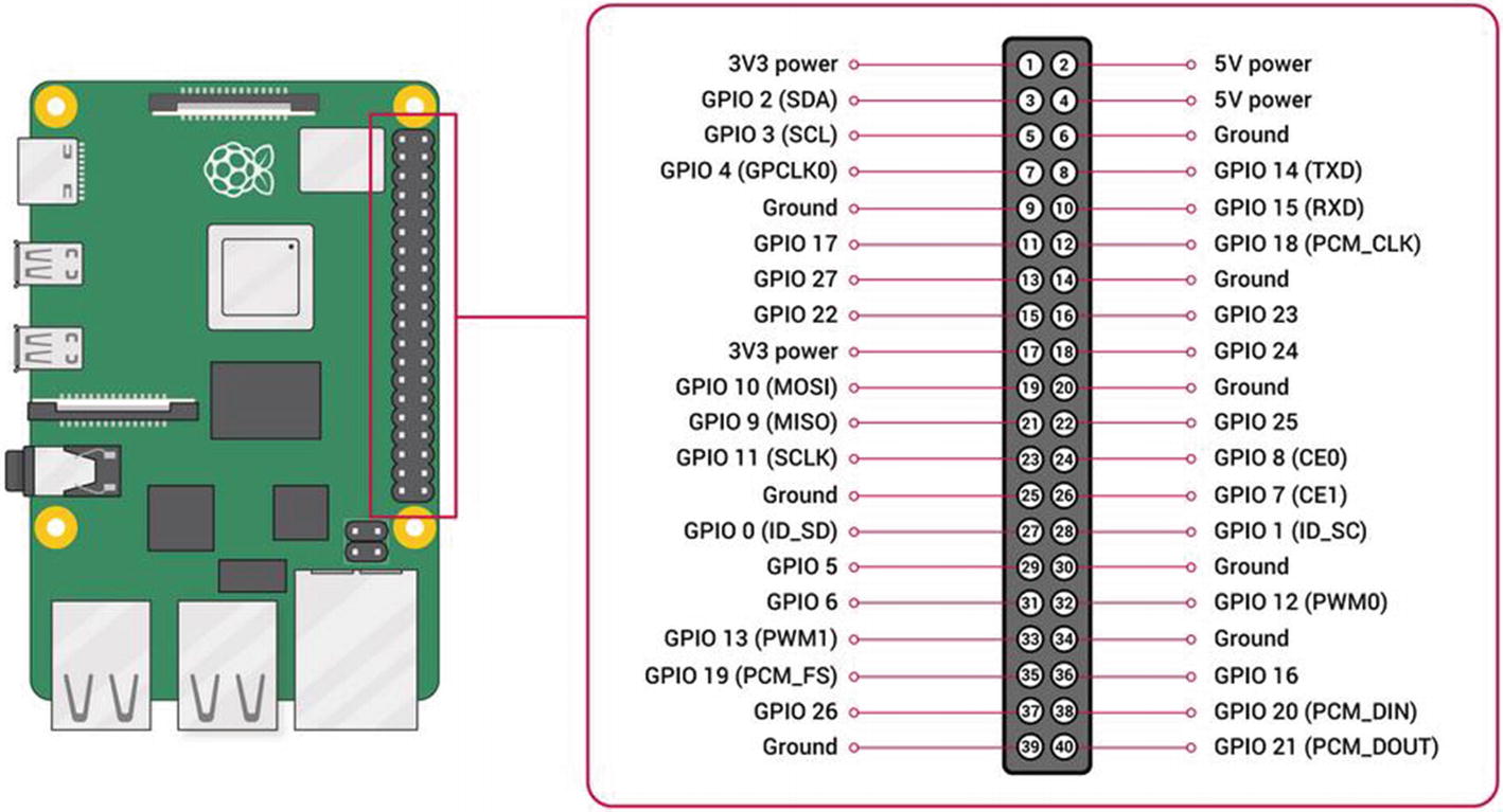
GPIO pin assignments (courtesy of raspberrypi.org)
Notice that the pins are not named in order. For example, there are GPIO 1 and GPIO 2, but they aren’t next to each other on the header (GPIO 1 is on the right at position or pin 28 and GPIO 2 is on the left at header position or pin 3). This naming may be a source of confusion because it doesn’t follow what you would expect, nor does it mirror the neat layout of microcontrollers like the Arduino. Thus, when working with the GPIO header, you should check your pin choices carefully.
Do not mistake pin number for GPIO number. Always double-check the name of the connection you want to use with the position or pin number it uses on the header. For example, GPIO 16 is not at pin 16, it is at pin 36.
Also notice that some pins have two names. For example, GPIO 14 and GPIO 15 are also named TXD (transmit) and RXD (receive), respectively. These pins can be used for serial communication. GPIO 18 and GPIO 21 are labeled PWM (pulse wave modulation), which is used for powering LEDs, motors, and similar devices. GPIO 0 and GPIO 1 are also named SDA and SCL, respectively, and are used for I2C communication. I2C is a fast digital protocol that uses two wires (plus power and ground) to read data from circuits (or devices). Finally, GPIO 9, GPIO 10, and GPIO 11 are also named MISO, MOSI, and SCKL, respectively, and are used for SPI communication.
All pins are limited to 3.3V. Attempting to send more than 3.3V will likely damage your Raspberry Pi. Always test your circuit for maximum voltage before connecting to your Raspberry Pi. You should also limit current to no more than 5mA.
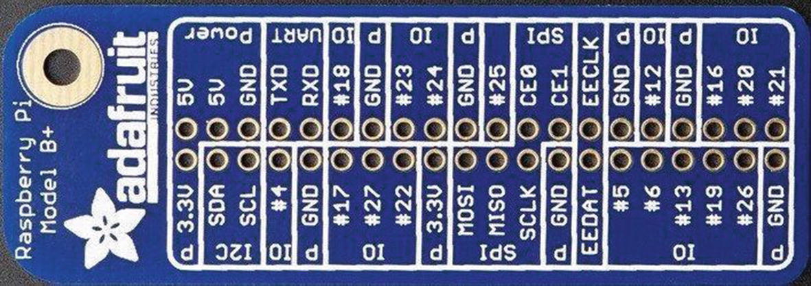
GPIO reference card (courtesy of Adafruit)
If you want to ensure that you are protecting your Raspberry Pi from higher voltage and current, most expansion boards have additional circuitry for power protection. A number of expansion boards are available, including the Gertboard (www.element14.com/community/docs/DOC-51726?ICID=raspberrypi-gert-banner). This book does not cover the use of expansion boards, but you may want to consider using expansion boards if your sensors involve complex circuitry that requires more ports or additional features like motor controllers or relays.
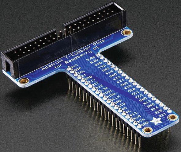
Pi T-Cobbler Plus breakout board (courtesy of Adafruit)
Whenever you want to connect sensors or circuits to the GPIO header—either directly (not recommended) or via a breakout board (recommended)—you should first shut down your Raspberry Pi. This may sound inconvenient and even like a pain when you’re working through a project, but it is the best method for ensuring that you do not accidentally short some pins or make the wrong connections.
I’ve found it best to make the connections with the Raspberry Pi powered off and to take a couple of passes verifying the connections are connected to the right pins. It is very easy to connect to the wrong pin—there are so many, and they are in close proximity. The odd arrangement of the pin numbers doesn’t help either. Properly admonished, let’s jump into working with your Raspberry Pi GPIO and hook up some sensors!

Pi Cobbler Plus breakout board (courtesy of Adafruit)
The Pi T-Cobbler Plus and Cobbler Plus may come partially assembled. You may need to solder (or have someone solder) the breadboard headers to the breakout board.
You can also find several variants on the Pi T-Cobbler Plus and Cobbler Plus on popular online auction and electronics discount sites. One fine example is the SparkFun Pi Wedge from SparkFun (www.sparkfun.com/products/13717). This board has a similar layout to the Pi T-Cobbler Plus but arranges the GPIO pins in a slightly different order (but is printed on the PCB for easy reference).
Whichever breakout board you choose, it will permit you to connect your Raspberry Pi to a breadboard, making experimentation with electronics (and sensors) much easier. It won’t protect you against accidental power overload, so be mindful of that. The following projects use a breadboard; so, if you have a Pi Cobbler, connect your Raspberry Pi to your breadboard.
Now that you know how to connect hardware to the GPIO pins, you need to know what software is required to allow you to write programs to read from and write to those pins.
Required Software
You need to install a number of software packages to work with the GPIO header. This section examines the required software for using the Python programming language. You can use C and Scratch language extensions, but Python is the best to learn because it is syntactically easy to read and easy to master. Also, the designers of the Raspberry Pi chose Python initially as its only language, so you are likely to find more examples on the Internet to which to refer for ideas and help. We have already seen a tutorial on MicroPython, and the Python we will be using on the Raspberry Pi is nearly identical at least in terms of how we write the code.
By default, the Raspbian includes Python and a host of supporting libraries. But it does not include everything you need. To fully access all the GPIO features, you also need the Raspberry Pi Python GPIO module (RPi.GPIO) for communicating with the GPIO pins, pySerial for connecting to serial devices, and python-smbus for accessing the I2C bus. If you use an expansion board, the manufacturer may also have special modules you need to install. No special modules are needed for the Pi T-Cobbler breakout board. If you are interested in writing games, you may also want to install the python-game package.
Now that you have the software loaded, it’s time to experiment! If you haven’t plugged in your breakout board, shut down your Raspberry Pi (using sudo shutdown –h now from a terminal or the shutdown from the Raspbian menu) and connect the breakout board, and then restart your Raspberry Pi.
Project: Hardware “Hello, World!”
In this project, you will build a “Hello, World!” project for the Raspberry Pi. This project uses an LED that the Raspberry Pi turns on and off through calls to a Python library function. That’s a fine project for getting started, but it does not relate to how sensors could be used.
Thus, in this section, you will use a modified LED project where we simply trigger an LED by adding a sensor. In this case, you still keep things simple by using what is arguably the most basic of sensors: a pushbutton. The goal is to illuminate the LED whenever the button is pushed.
Hardware Connections
Let’s begin by assembling a Raspberry Pi, Pi T-Cobbler from Adafruit (optional), breadboard, one LED, and one pushbutton. You start with the Raspberry Pi powered down.
Plug the breakout board into the breadboard. Wire the 3.3V pin, not the 5V pin, to the breadboard power rail, the ground pin to the ground rail, and a loop around to the other side of the board. This connection provides power to the breakout board. Thus, you do not need a breadboard power supply.
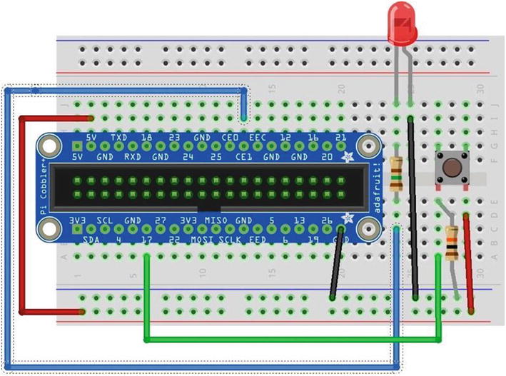
Diagram of an LED with a pushbutton
Connecting the 5V pin to any other pin on the GPIO header can damage your Raspberry Pi. If you use a sensor that requires 5V input, be sure to double-check that its maximum output is 3.3V or less.
You’re almost there. Now wire a jumper from the power rail to one side of the pushbutton, and wire the other side of the pushbutton to pin GPIO 17 on the breakout board (pin 6 on the left side). Wire the LED to ground on the breadboard and a 150 Ohm resistor (colors: brown, green, brown, gold). The other side of the LED should be wired to pin GPIO 7 on the breakout board (see Figure 5-13).
You also need a resistor to pull the button low when the button is not pressed. Place a 10K Ohm resistor (colors: brown, black, orange, gold) on the side of the button with the wire to pin GPIO 17 and ground. The shortest side of the LED is the ground side. This side should be the one connected to the resistor. It does not matter which direction you connect the resistor. It is used to limit the current to the LED. Check the drawing again to ensure that you have a similar setup.

Although you can make your own Raspberry Pi mounting plate from Lexan or Plexiglas, the Adafruit product is a notch better than what you can make yourself. For about $23.00, you can keep your Raspberry Pi and breadboard together and avoid scratches to your table and shorts caused by components on the bottom of the Raspberry Pi coming into contact with conductive material.
Writing the Script
The script you need for this project requires two pins: one output and one input. The output pin will illuminate the LED, and the input pin will detect the pushbutton engagement. You connect positive voltage to one side of the pushbutton and the other side to the input pin. When you detect voltage on the input pin, you tell the Raspberry Pi processor to send positive voltage to the output pin. In this case, the positive side of the LED is connected to the output pin.
As you can see in the drawing in Figure 5-13, the input pin is pin GPIO 17 and the output pin is pin GPIO 7. Let’s use a variable to store these numbers so you do not have to worry about repeating the hard-coded numbers (and risk getting them wrong). Use the GPIO.setup() method to set the mode of each pin (GPIO.IN, GPIO.OUT).
Recall, indentation is important in Python. Indented statements form a code block. For example, to execute multiple statements for an if statement, indent all the lines that you want to execute when the conditions are evaluated as true.
Simple Sensor Script
To save yourself a lot of typing, you can download the code for this chapter or any of the examples in the book from the Apress website.
I use python3 and later pip3, which execute for Python version 3. Use this on the latest version of Raspbian. Older releases or other distributions may not support Python3, in which case you can omit the “3” from the command.
Testing the Sensor
Once the script is started, what do you see on your Raspberry Pi? If you’ve done everything right, the answer is “Nothing.” It’s just staring back at you with that one dark LED—almost mockingly. Now, press the pushbutton. Did the LED illuminate? If so, congratulations: you’re a Raspberry Pi Python GPIO programmer!
If the LED did not illuminate, hold the button down for a second or two. If that does not work, check all of your connections to make sure you are plugged in to the correct runs on the breadboard and that your LED is properly seated with the longer leg connected to the resistor and to pin GPIO 7.
On the other hand, if the LED stays illuminated, try reorienting your pushbutton 90 degrees. You may have set the pushbutton in the wrong orientation.
Try the project a few times until the elation passes. If you’re an old hand at Raspberry Pi, that may be a very short period. If this is all new to you, go ahead and push that button and bask in the glory of having built your first sensor node!
Now, how do you stop it? Because you coded an endless loop (intentionally), you need to use Ctrl+C to cancel the script. This will not harm your Raspberry Pi or the GPIO or the circuitry.
The next section examines a more complicated sensor node using a temperature and humidity sensor.
For More Fun
Loop for no more than 10,000 iterations. Hint: Use a variable and increment it.
Use a second LED, and set up the code to toggle both LEDs so that when the button is pressed, one illuminates and the other turns off.
Use a second button so that when the second button is pressed, the loop terminates. Hint: Use sys.exit() or break.
Hosting Sensors with Raspberry Pi
The GPIO pins of the Raspberry Pi make it an ideal platform for hosting sensors. Because most sensors need very little in the way of supporting components, you can often host multiple sensors on one Raspberry Pi. For example, it is possible to host a temperature sensor or even multiple temperature, barometric, humidity, and other sensors for sampling weather conditions from a given site.
The Raspberry Pi GPIO pins do not support digital signals—they are all analog pins. This is one of the many small cost considerations that help keep the price down. To access digital signals, you need an analog-to-digital controller. If you encounter a situation in which you want to use a digital sensor, you can look at the 12-bit ADC—4 Channel with Programmable Gain Amplifier from Adafruit (www.adafruit.com/products/1083).
As I discussed in Chapter 1, a host of sensors are available. SparkFun and Adafruit each have excellent websites that provide a great deal of information about the products they sell. You can also google for examples of using analog sensors with the Raspberry Pi.
Although this chapter demonstrates how to host sensors with the Raspberry Pi using a breakout board connected to a breadboard, the restriction of using analog only and 3.3V maximum voltage makes the Raspberry Pi less versatile than the Arduino. Add to that the fact that you must run Python scripts using root, and hosting sensors on a Raspberry Pi becomes a bit harder to do (but not overly so) and more cumbersome than doing so with an Arduino.
You can still connect sensors directly to the Raspberry Pi, as you see in the next section. However, you may want to consider using the Raspberry Pi as an aggregate node using an XBee connected to XBee-hosted sensors or even Arduino-hosted sensors. But first, let’s see how to connect a sensor to the Raspberry Pi and read some data.
To make things easier, you use a project similar to the one you used in Chapter 3. More specifically, you build a sensor node with a Raspberry Pi and a single temperature sensor. Before you begin, let’s discuss some safety factors related to working with the Raspberry Pi GPIO header.
Project: Building a Raspberry Temperature Sensor Node
The next project you explore is another temperature sensor example. This time, you use a temperature sensor that utilizes a special digital protocol to send. As mentioned previously, the Raspberry Pi does not have an analog-to-digital converter.
Although this may be yet another temperature sensor node, the project also gives you experience in reading digital sensors that use the one-wire protocol—which is built into the Raspberry Pi GPIO. Specifically, you use the DS18B20 digital temperature sensor available from SparkFun and Adafruit.
In some respects, the hardware portion of this project is easier than the previous project because there are fewer parts; but the code is more complex. Let’s begin with the hardware setup.
Hardware Setup

Connecting a temperature sensor to a Raspberry Pi
Next, install the temperature sensor to the right of the breakout board with pin 1 to the left. If you hold the sensor such that the flat side is facing you, pin 1 is on the left of the flat side of the sensor. Connect the 0.10mF capacitor between pin 3 (right) and pin 2 (center) or use jumpers as shown in Figure 5-15.
Connect power from the breakout board to the power rail of the breadboard and ground from the breakout board to the ground rail of the breadboard, as shown in Figure 5-14. Next, connect power to pin 3 of the sensor and ground to pin 1. Finally, connect pin 2 of the sensor to GPIO 4. Why GPIO 4? Because the sensor is a digital sensor, and you can use the one-wire facility (because it uses only a single data wire) to read the data. Cool, eh?
If you have the waterproof version of the DS18B20 digital temperature sensor, the sensor has four wires. Typically, the wires are colored red, black, white or yellow or orange, and copper or silver. The copper or silver wire is not used; it is part of the shielding. The red wire is connected to power, the black wire is connected to ground, and white or yellow or orange is the data wire.
Testing the Hardware
Once you have double-checked your connections, go ahead and boot up your Raspberry Pi. Because the sensor uses the one-wire protocol to read data, you can use features built into the Raspberry Pi to read data from the sensor. This isn’t nearly as elegant as writing a Python script, but it will permit you to see that all is working correctly before you start programming.
You will use a special utility called modprobe . This utility loads (or unloads) modules into the Linux kernel. In the vernacular of other operating systems, it loads device drivers. The modprobe utility can do far more than just load modules (drivers); to learn more about it, see http://linux.die.net/man/8/modprobe.
The modules you want to load are named w1-gpio and w1-therm. The w1-gpio module registers and loads the new sensor connected to pin GPIO 4. The w1-therm module registers and loads a module that has support for temperature sensors.
When you use modprobe to load each of these modules (w1-gpio first), the Raspberry Pi enables data collection on pin GPIO 4 and reads data from the sensor and stores it in a file. The file is named starting with 28 and followed by a unique file name. If you had other sensors, there would be a file for each one.
The file is created whether there is a sensor created or not, but to see meaningful data, you should shut down, wire the sensor, and then reboot before checking the file.
Testing the Temperature Sensor Hardware
Notice that in the example I ran the cat9 (concatenate and print) utility to print out the data in the file several times. I placed my hand over the sensor while running the utility in order to simulate an increase in temperature. Can you see how the values changed?
Software Setup
Notice that you know the parent directory and the starting portion of the directory. The glob module does all the work for you. If there were multiple directories matching the wildcard, the call would return a list. In this case, you have only one sensor, so you can expect only one directory.
As you can see, it is very straightforward and reads like the steps you would imagine. Specifically, you open the file, read all the lines in the file, close the file, and return what you read.
This method has two parts. The first part reads the data from the file using the previous method and checks the first line (arrays and lists start with index 0 in Python) to see if the status is YES . If it isn’t, you read the line from the file again and repeat until you find a file that has the correct, valid status.
The next part looks in the file for the data read. In this case, you look for a substring that starts with t= and then read the data after that and convert it to Celsius and Fahrenheit. You return those values for use in printing the data.
Let’s put it all together. Listing 5-3 shows the completed script, including documentation. Open an editor, create a file named pi_temp.py, and enter the source code shown. Feel free to modify it to suit your mood or particular brand of humor.
The pi_temp.py Script
Take a few minutes to double-check your file to make sure you have typed all the statements correctly. If you have an editor on your desktop or laptop, you might want to use it to create and edit the file using the syntax-checking feature to catch any errors. The script won’t run correctly on your desktop or laptop, but checking the syntax can be a big help.
Now that the software is written, let’s see what it does.
Testing the Sensor
If you get syntax errors, go back and check that you have entered every line exactly as shown in Listing 5-3. Python is really good at providing enough information to fix most syntax errors. If you encounter any, you see not only what the error is but also the line number of the file where the error occurs. Once you have fixed the error, try the script again until you see the correct output.
The next section explores a more complex project in which the Raspberry Pi communicates with a digital sensor that uses the I2C protocol.
For More Fun
To make this project a bit more fun, try connecting a second sensor (of the same type), and print out the data including the sensor from which the data was read. Hints: You can use the serial number embedded in the file to identify the sensor, and you should connect them in parallel. That is, each sensor connects to the same ground (pin 1) and power connections (pin 3). The data output (pin 2) of each sensor is wired to the same GPIO pin.
For extra-special fun, modify the code to detect when the sensor read has failed and print an appropriate error message. Can you spot where this is possible?11 I’ll give you a hint: what happens in the get_temp() method if t= is not found?
Project: Building a Raspberry Barometric Pressure Sensor Node
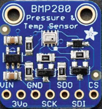
BMP280 I2C sensor (courtesy of Adafruit)
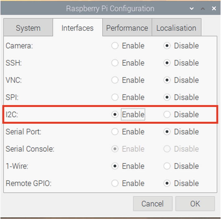
Enable the I2C interface
That’s it! You are now ready to begin connecting the hardware. The hardware portion of this project is easier than that in the previous project because there are fewer parts, but the code is more complex. Let’s begin with the hardware setup.
Hardware Setup
The hardware needed for this project is a breadboard, a breakout board for the Raspberry Pi (such as Pi Cobbler+), a BMP280 sensor module, and some jumper wires. Insert your breakout board into the breadboard, aligning pin 1 (3.3V) to position 1 on the breadboard.

Connecting the BMP280 sensor to a Raspberry Pi
Testing the Hardware
Notice in the example that the graph shows data in column 7 for row 70 and a value of 77. This means the sensor is at address 0x77 (in hexadecimal). If other sensors were installed, they would appear in the graph as well. Remember this address, because you need it for the code.
If you do not see any devices in the output from this command, try it with –y 0 and see if this produces any output. For example, use sudo i2cdetect -y 0.
Software Setup
The software required for this project requires the Python libraries you installed earlier as well as a special library designed to communicate with the BMP280. You need a special module because the I2C protocol is bidirectional, and most I2C components are designed to respond to one or more commands to evoke data generation. In this case, you need a Python module that supports the BMP280 sensor module.
The library has been created by the nice people at Adafruit and is available for download from the Python package repository (PyPi12). You can find comprehensive documentation for the library at https://readthedocs.org/projects/adafruit-circuitpython-bmp280/downloads/pdf/latest/.
A number of I2C sensor modules are available. However, corresponding Python (or other language) libraries have not been built for all of them. You should research the availability of a library to support the sensor prior to deciding to use it in your network. If you are a programmer, you may be able to adapt existing code (libraries) to add support for the new sensor by examining the datasheet and writing appropriate commands to interact with the sensor.
Now let’s put it all together. Listing 5-4 shows the complete listing of the script. Open an editor, create a file named pi_bmp280.py, and enter the source code shown.
The pi_bmp280.py Script
Now that the software is written, let’s see what it does.
Testing the Sensor
The next section explores a more complex project in which the Raspberry Pi is a data collector (an aggregate node) hosting sensor data via an XBee wireless connection to a sensor node. You will reuse the sensor node created in Chapter 4. If you have not read through and succeeded in building the projects in Chapter 4, you may want to go back and complete the last project before proceeding.
For More Fun
The BMP280 sensor reads the barometric pressure, as you have seen, but it also reads temperature. Change the previous code to read the temperature data as well as the barometric pressure.
Project: Creating a Raspberry Pi Data Collector for XBee Sensor Nodes
This project combines what you have learned about the Raspberry Pi in this chapter and the XBee in Chapter 2 and the XBee sensor node from Chapter 4. More specifically, you use a Raspberry Pi and a remote sensor connecting the sensor with the Raspberry Pi using XBee modules. You know the basics from Chapter 4, so let’s dive right in.
XBee Sensor Node

XBee sensor node
XBee Sensor Node Options and Values
Code | Setting Name | Description | Value |
|---|---|---|---|
D3 | AD3/DIO3 | Trigger analog or digital data recording | 2—ADC |
ID | PAN ID | Id for the network | 8088 |
NI | Node Identifier | Name for the node | TMP36 |
V+ | Supply Voltage Threshold | Supply voltage | FFFF (always send) |
Be sure to use “TMP36” for the node id (NI). Your project will not return results unless the node id matches the value in the following code.
XBee Coordinator Options and Values
Code | Setting Name | Description | Value |
|---|---|---|---|
ID | PAN ID | Id for the network | 8088 |
NI | Node Identifier | Name for the node | Coordinator |
Hardware
The hardware setup for this project is very easy. All you need to do is use the serial interface that is part of the GPIO header to connect to the XBee’s serial interface. It’s that easy! Do not power on your Raspberry Pi or sensor node until after all hardware connections are complete and verified correct. I will tell you when to power up later in this section.
You need a breadboard and an XBee breadboard adapter like the one you used in Chapter 4; plug it into the breadboard. Then plug in your Raspberry Pi breadboard adapter. Now wire the 3.3V and ground to the pins on your XBee adapter. If you are using the XBee Explorer Regulated from SparkFun (www.sparkfun.com/products/11373), you can connect to the 5V power because the XBee Explorer can regulate the power (hence the name). The SparkFun board as shown has the serial interface pins arranged in a header on one side of the board. It also has onboard voltage regulation to protect the XBee in the event you accidentally connect the 5V pin instead of the 3.3V pin to the explorer.
If you have soldered breadboard headers to the XBee adapter but have not soldered headers for the serial I/O header, take a moment to do that. You can connect the XBee via the other header, but the consolidated header makes it a bit easier.

Connecting an XBee to a Raspberry Pi
If you are not using the SparkFun adapter , be sure to check the documentation on your adapter to make sure you are connecting the right pins. Take your coordinator XBee module and insert it into the XBee.
There is one more thing you need to do. The designers of the Raspberry Pi included the facility to connect a serial terminal to the Raspberry Pi at boot time. There is a setting in the preferences that allows you to enable this interface. It is disabled by default.
To turn on the serial interface, open a terminal and enter the command sudo raspi-config . This opens the Raspberry Pi configuration tool. To enable the serial interface, select the Interfacing Options in raspi-config. The easiest way is to use the arrow keys and highlight the selection and press ENTER.
On the next screen, choose the Serial option, then follow the next three screens to disable login shell over serial (choose No), enable the hardware serial port (choose Yes), and then press ENTER on the confirmation page.

Enabling the serial interface (raspi-config)
After your machine reboots, we can install the software we need for the project.
Software
This library has a host of classes used to work with XBee modules and has numerous examples you can use for your own projects. We are going to see just one of the ways you can use the library. For more details about other features in the library, you can download the Digi-Python Programmers Guide using the following URL: https://xbplib.readthedocs.io/en/latest/getting_started_with_xbee_python_library.html
If you want to see the code for the library itself, you can see it on GitHub at https://github.com/digidotcom/xbee-python.
If you have changed the baud rate of your XBee module, you must use that baud rate here.
Now we’re ready to get to the core of the program. We will use two techniques that you may not have seen before using methods. First, we will create a method to connect to the ZigBee network and retrieve an instance of the remote XBee module class that we can use to read data. Second, we will create a second method to be used to read data at the sampling rate. This is called a callback method since it is used by the libraries to “call back” to your program whenever the sampling rate dictates reading data.
Notice we also placed the code to decipher the data in this method. Specifically, we calculate the temperature in Celsius, convert it to Fahrenheit, and calculate the voltage at the node. I leave the details of the code as an exercise, but we’ve used the formulas in previous examples.
Reading Data from an XBee Module
Testing the Final Project
Output of the XBee Aggregate Node Script (pi_xbee.py)
Did you see something similar? If so, you’re doing great work and now have the knowledge needed to build sensor nodes and Raspberry Pi–based sensor data aggregators.
If you do not see any data at all, go back to Chapter 4 and follow the troubleshooting tips from the last project in the chapter. You can always plug the coordinator module into a USB explorer and use a terminal program on your personal computer to see if data is being received from the XBee sensor node.
If you don’t see any data, power off your sensor node and Raspberry Pi. Remove the coordinator module from the Raspberry Pi, plug it into a USB XBee Explorer, plug that into your personal computer and connect a serial program to the port, and then power up your sensor node. After a few moments, you should see data being received on the coordinator node.
For More Fun
If you would like to expand the project, you can add a second XBee sensor node and modify the code to specify which node the data came from. For example, the script should record (write to standard output) the source of the data along with the sensor data from the XBee.
Component Shopping List
Components Needed
Item | Vendors | Est. Cost USD | Qty Needed |
|---|---|---|---|
Raspberry Pi Model B | Most online stores such as Adafruit, SparkFun, and Mouser | $35.00 and up13 | 1 |
5V Power Supply (3A, 3B, 3B+) | www.pishop.us/product/wall-adapter-power-supply-micro-usb-2-4a-5-25v/ | $9.95 | 1 |
5V Power Supply (4B) | $8.00 | 1 | |
HDMI or HDMI to DVI cable | Most online and retail stores | Varies | 1 |
HDMI or DVI monitor | Most online and retail stores | Varies | 1 |
USB keyboard | Most online and retail stores | Varies | 1 |
USB Type A to micro-USB male | Most online and retail stores | Varies | 1 |
SD card, 2GB or more | Most online and retail stores | Varies | 1 |
Raspberry Pi Cobbler+ (you can also use the T-Cobbler+) | $7.95 | 1 | |
150 Ohm Resistor | Most online and retail stores | Varies | 1 |
0.10mF capacitor | Most online and retail stores | Varies | 1 |
10K Ohm Resistor | Most online and retail stores | Varies | 1 |
LED | Most online and retail stores | Varies | 1 |
DS18B20 Digital Temperature Sensor | $3.95 | 1 | |
Pushbutton | Most online and retail stores | Varies | 1 |
BMP280 Sensor | $9.95 | 1 | |
Breadboard (not mini) | $5.95 | 2 | |
XBee Explorer Regulated | $9.95 | 2 |
Summary
In this chapter, you explored the origins of the Raspberry Pi, including a tour of the hardware and a list of the available operating systems. You discovered how to create an SD boot image and learned how to start using the Raspberry Pi.
You also discovered how to use the GPIO header to illuminate an LED, read data from sensors, and read data via an XBee from an XBee sensor node. By executing these projects, you have learned far more about the Raspberry Pi than most.
By now, you should start to see the parts of building a sensor network coming together. You’ve explored XBee modules for wireless communication, host sensors with XBee and Raspberry Pi, and even how to build aggregate sensor nodes with both platforms.
We complete our tour of sensor nodes by examining the Arduino platform. In the next chapter, we will learn what the Arduino is and how to host sensors with it. Cool!