© Satheesh Pv 2021
S. PvBeginning Unreal Engine 4 Blueprints Visual Scriptinghttps://doi.org/10.1007/978-1-4842-6396-9_5

5. Physics and Raycasting

Satheesh Pv1  
(1)
Mumbai, India
 

Physics in Unreal Engine is responsible for the simulation and collision of all physical actors, which means any motion, like falling or applying a force or interaction between them is done using physics. At the time of this book was written, Unreal used PhysX version 3.4, which was used for all simulations.

UE4 includes a built-in high-performance custom physics engine called Chaos Physics Engine, which (at the time of writing this book) is only available through the GitHub source. Chaos Physics is expected to be production-ready in UE4 version 4.26.

Raycasting (also known as trace) is the process of sending an invisible ray from one location to another location in the game world and determining if the ray hit anything. The hit result contains information that you can use to alter the game state.

In this chapter, you learn about Simulation, Collision, and Trace.

Simulation

When an object is falling or moved by applying some force, then that object is simulating physics. For physics to simulate, the mesh must have a collision shape first. Because the actual 3D mesh can be complicated, UE4 uses simple proxy shapes, which are called Physics Bodies (also known as BodyInstances), such as a box, sphere, capsule, or custom convex hull to simulate physics. The properties for this physical body are adjusted by selecting the mesh on which you want to apply physics. For example, in Chapter 3, we assigned a Static Mesh Component and created a Blueprint class for our C++ actor.
  1. 1.

    Open the Blueprint and select MeshComponent (Inherited) from the Components tab (see Figure 5-1).

     
../images/496849_1_En_5_Chapter/496849_1_En_5_Fig1_HTML.jpg
Figure 5-1.

Inherited Mesh Component

  1. 2.

    In the Details panel, scroll down to the Physics category (see Figure 5-2).

     
../images/496849_1_En_5_Chapter/496849_1_En_5_Fig2_HTML.jpg
Figure 5-2.

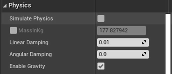
Physics category in details panel

Let’s look at these properties.
  • Simulate Physics: Enables or disables physics simulation. If this option is grayed-out, you don’t have a collision set up on the selected mesh. For Skeletal Mesh, you need a physics asset setup, and for Static Mesh, you need a simple collision setup.

  • MassInKg: The mass of the object in kilograms.

  • Linear Damping: The drag force applied to a linear movement, which determines the movement in a straight line.

  • Angular Damping: The drag force applied to an angular movement, which is the rotational equivalent of linear movement.

  • Enable Gravity: Determines if the physics simulation should have the force of gravity applied.

Collision

In Unreal, every object with Collision is assigned an object type, which defines how it interacts with other object types. Some object types can block, some can overlap, and others can ignore. An object can also define how it should react to traces using trace channels. By default, there are two types of trace channels: Visibility and Camera.

There are two types of collisions: Blocking and Overlaps.
  • Blocking collisions occurs when two objects collide and cannot pass through (e.g., an object hitting a wall).

  • Overlap collisions occur when two objects overlap each other (e.g., an object falling into water).

Collisions are determined by the preset on the component under the Collision category. Collisions generate events with information, including with whom the collision occurred. Figure 5-3 shows the Collision properties.
../images/496849_1_En_5_Chapter/496849_1_En_5_Fig3_HTML.jpg
Figure 5-3.

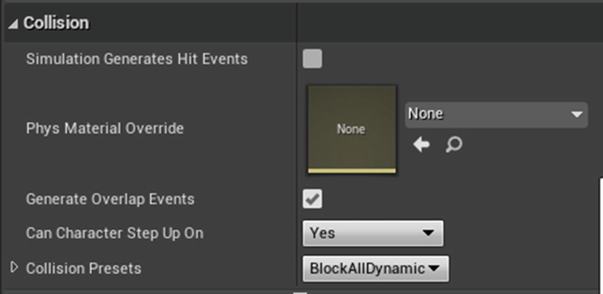
Collision properties of static mesh

  • Simulation Generates Hit Events: If true, this physics body calls a native On Component Hit event when a collision is a success.

  • Phys Material Override: Assign a physics material (not to be confused with the material in the next chapter) to define properties such as Friction, Restitution, and Density.

  • Generate Overlap Events: If true, this physics body calls a native On Begin Overlap event when the overlap starts and calls an On End Overlap event when overlapping ends.

  • Can Character Step Up On: Determines if the player character can step onto this object. If No, the player is rejected if they try to step on it.

Collision has four different states.
  • No Collision: There is no representation for any type of collision. This means no overlapping or blocking.

  • Query only: The object can only trigger overlap events, and no rigid body collisions; the object cannot block any other objects.

  • Physics only: The object can interact with other objects but does not support overlaps.

  • Collision enabled: The object can overlap and block other objects.

Let’s now look at defining a new trace type and using it in the game to pick up an item.

Using Trace (Raycast) to Pick up an Item

When you want to pick up an item in a game, you look at the item first and press a specific key. When you press that key, under the hood, the Engine sends an invisible ray from the camera location with a specified length. In between the start location and the end location, if the trace hits an object, it returns a hit result containing hit information. Figure 5-4 illustrates how trace works.
../images/496849_1_En_5_Chapter/496849_1_En_5_Fig4_HTML.jpg
Figure 5-4.

Example showing how trace works

So how does the trace know what to hit? It is done using a trace channel. Unreal Engine comes with two trace channels: Visibility and Camera. In this section, you create our own trace channel, set it to an item, and use trace to detect it.

First and foremost, let’s create a trace channel. Open Project Settings by clicking Edit on the menu bar, and then select Project Settings (see Figure 5-5).
../images/496849_1_En_5_Chapter/496849_1_En_5_Fig5_HTML.jpg
Figure 5-5.

Accessing Project settings

From the Project Settings, click Collision under the Engine section to modify the collision settings (see Figure 5-6).
../images/496849_1_En_5_Chapter/496849_1_En_5_Fig6_HTML.jpg
Figure 5-6.

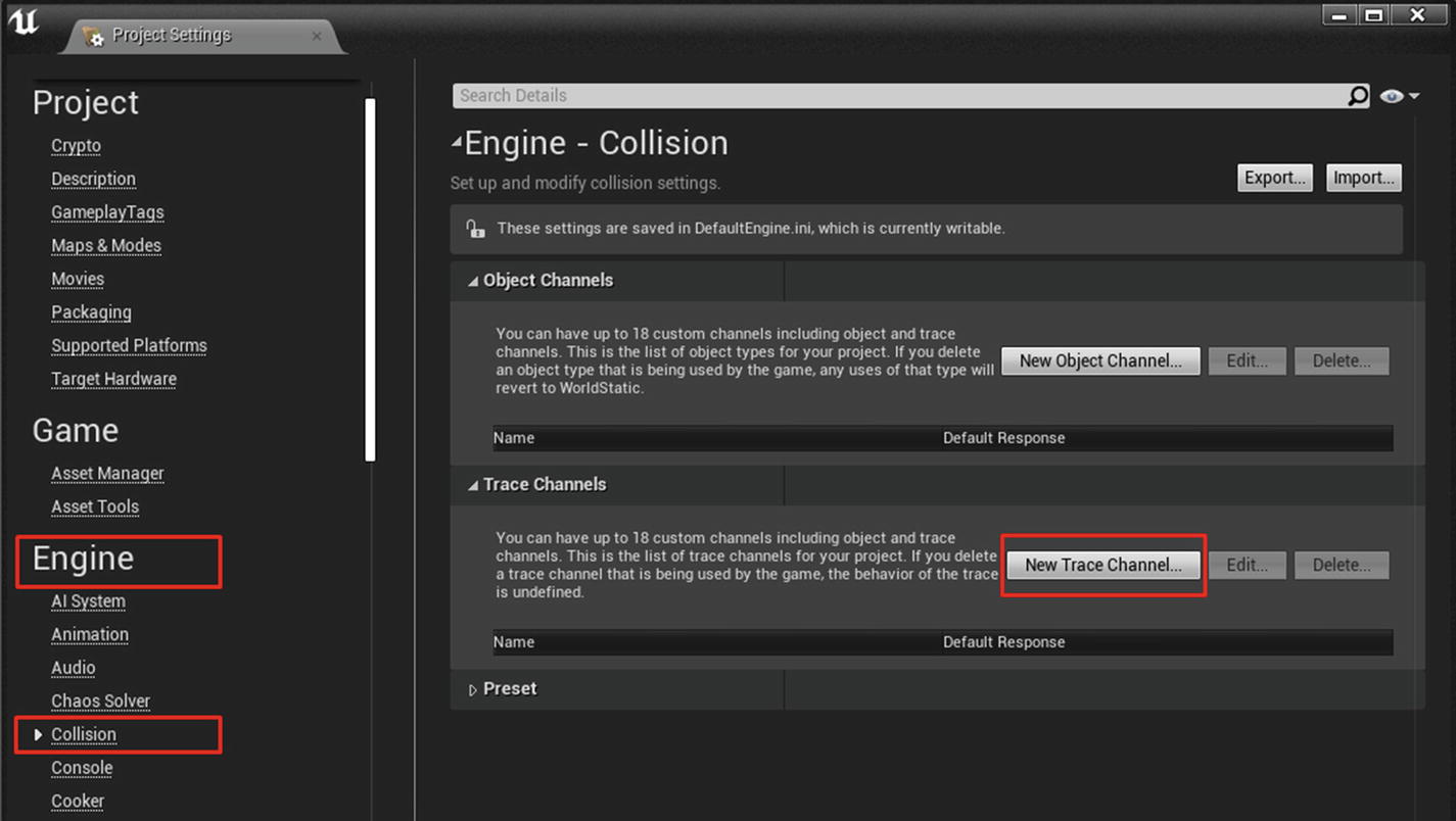
Adding new Trace channel

Click the New Trace Channel button under the Trace Channels category. A new dialog box appears, prompting you to name the trace and a default response. Enter the name as MyItemTrace and set the default response to ignore (see Figure 5-7).
../images/496849_1_En_5_Chapter/496849_1_En_5_Fig7_HTML.jpg
Figure 5-7.

Defining new trace with name and response

After pressing the Accept button, you see your newly created trace under the Trace Channels category. You can now access this trace channel under every mesh component to enable or disable it.

Before we do anything else, let’s first make sure the mesh you are using (1M_Cube) has collision available. Go to the Content Browser where the mesh is located, and hover your mouse over the mesh. In the tooltip, if the Collision Prims is greater than 0, then the mesh has collision included (see Figure 5-8).
../images/496849_1_En_5_Chapter/496849_1_En_5_Fig8_HTML.jpg
Figure 5-8.

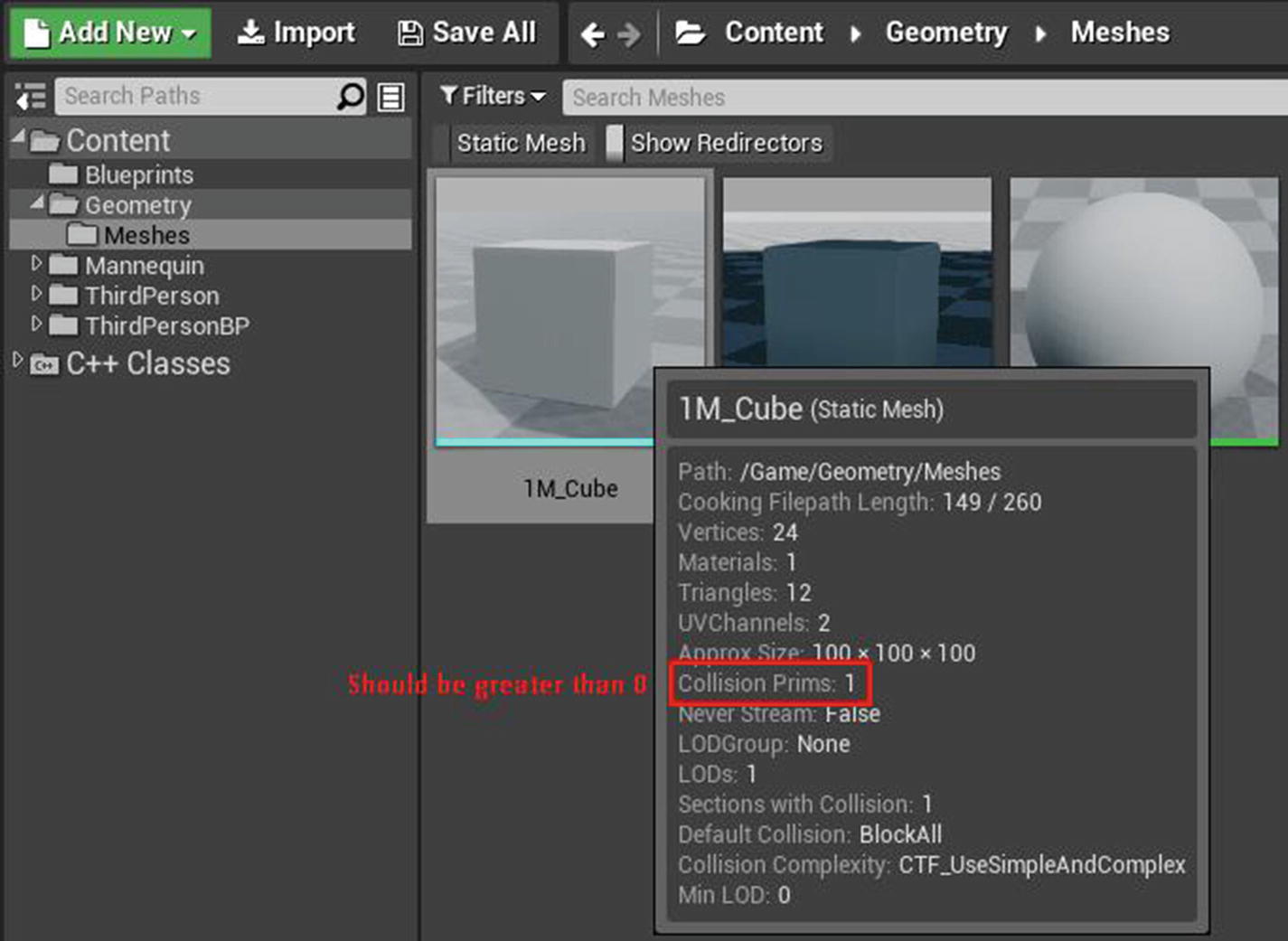
Tool tip showing number of collision primitives
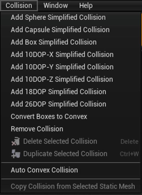
If the mesh is a missing collision, you can generate a collision shape inside the Static Mesh Editor. From the menu bar, click Collision and select an option to generate your desired collision shape. For simple shapes, you can choose box, cylinder, sphere, or so forth, but for complex shapes, select Auto Convex Collision (see Figure 5-9).
../images/496849_1_En_5_Chapter/496849_1_En_5_Fig9_HTML.jpg
Figure 5-9.

Various collisions

To use the trace channel, you first open your previously created Blueprint Actor and select the MeshComponent (inherited) from the Components tab. Assign the Collision that includes Static Mesh. In our case, you use the 1M_Cube static mesh.

Next, go to the Details panel and scroll down to the Collision category. Expand the Collision Presets section and click the BlockAllDynamic drop-down button. From the list of options, select Custom. By selecting Custom, you can choose how the object responds to collisions with other objects. Choose to block the MyItemTrace trace response by enabling Block (see Figure 5-10).
../images/496849_1_En_5_Chapter/496849_1_En_5_Fig10_HTML.jpg
Figure 5-10.

Setting our trace to block

You have now finished the item setup, but what about trace? You do it in the Character class, but you need to have an input to start the trace. To do that, click Edit on the menu bar and select Project Settings. Next, select Input under the Engine section. On the right, click the + button next to Action Mapping. Name the input anything you want, and select a key for it. I named it Trace and chose E for the key (see Figure 5-11).
../images/496849_1_En_5_Chapter/496849_1_En_5_Fig11_HTML.jpg
Figure 5-11.

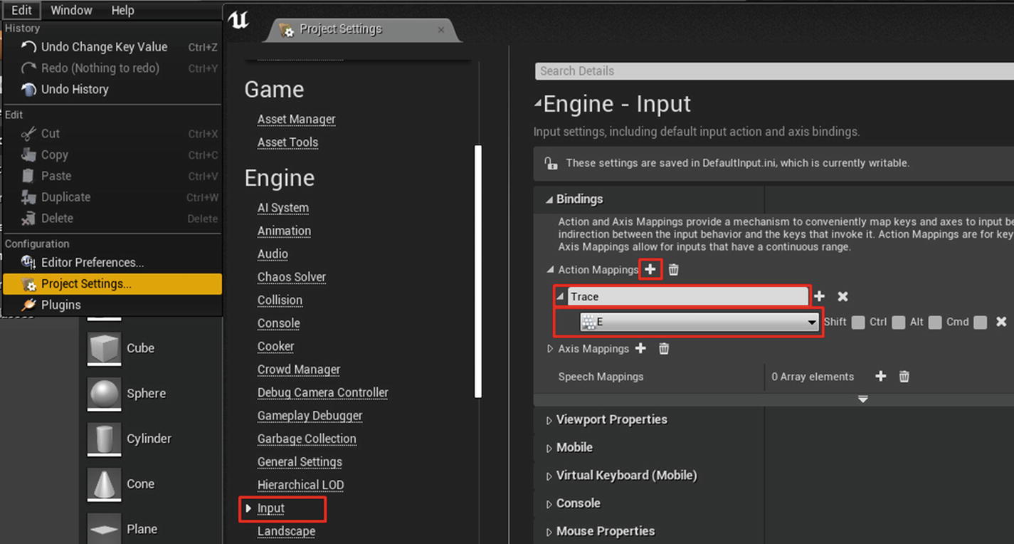
Creating new input to trace

If you have not added a third-person project, you can do so by clicking the green Add New button in the Content Browser. Select either Add Feature or Content Pack. In the dialog, select Third Person and click +Add to Project.

Next, press Shift+Alt+O to open the Open Asset dialog. Search for ThirdPersonCharacter and open it. Alternatively, you can navigate to Content/ThirdPerson/Blueprints and open ThirdPersonCharacter Blueprint (see Figure 5-12).
../images/496849_1_En_5_Chapter/496849_1_En_5_Fig12_HTML.jpg
Figure 5-12.

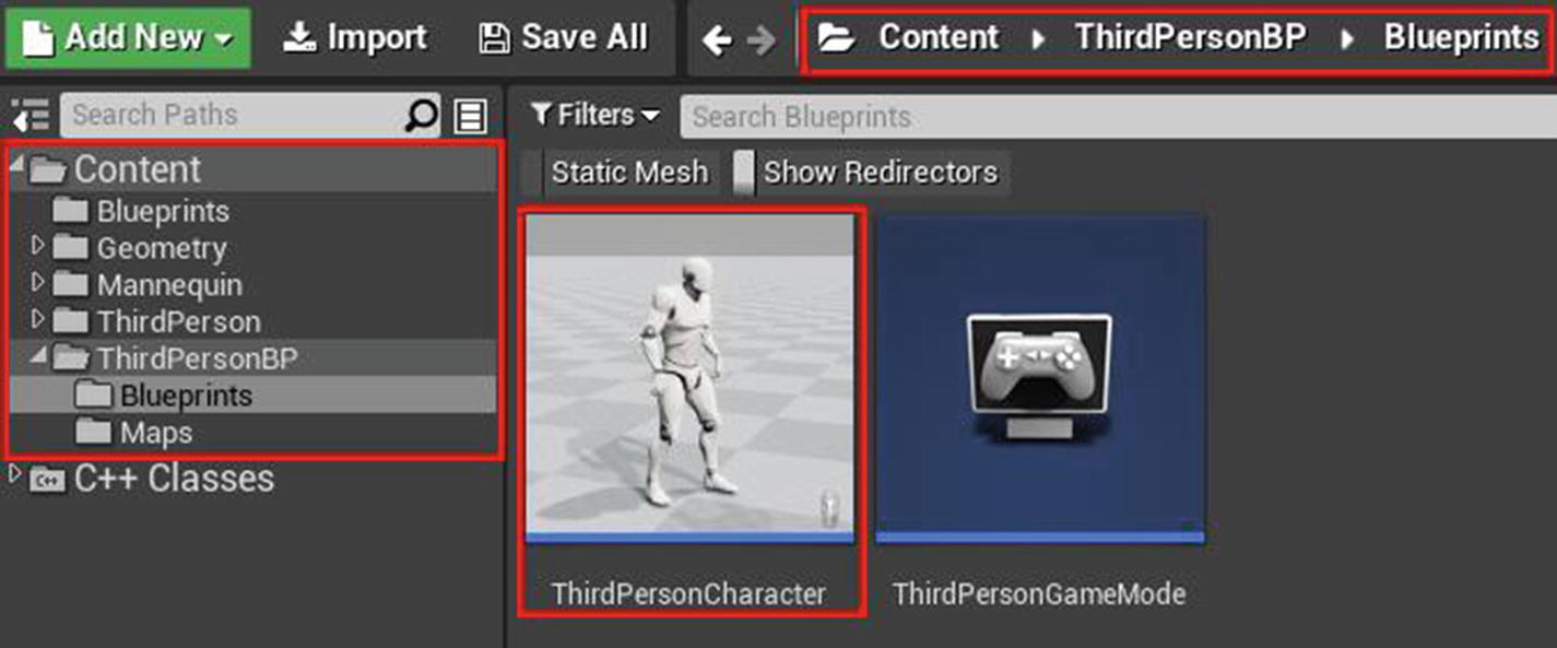
Open third person character

In the Event graph, right-click and search for Input Trace (it is under Input → Action Events). You can add the Trace event, which is invoked when you press the E key. Right-click again on the graph and search for Line Trace By Channel. (There are other types of traces as well, like Box, Capsule, and Sphere. Read more about them at https://​docs.​unrealengine.​com/​en-US/​Engine/​Physics/​Tracing/​Overview/​index.​html).

Line Trace By Channel is the primary node that does the tracing from the start location to the end location. Figure 5-4 illustrates where the trace starts from the Camera and shoots to the direction the Camera is facing. To create that setup, right-click the graph and search for GetFollowCamera (no spaces) and select the Get Follow Camera node. This is the getter node for the Camera included with the character in Components. (Alternatively, you can drag the Follow Camera from the Components tab onto the graph to create the node).

From the output pin of this node, drag a wire, search for GetWorldLocation, and select it. This node shows the Camera component’s location in the world space. Connect the GetWorldLocation yellow output to the Start input of Line trace node (see Figure 5-13).
../images/496849_1_En_5_Chapter/496849_1_En_5_Fig13_HTML.jpg
Figure 5-13.

Setting up line trace start location

Now you need the trace to end at a specified length where the Camera is looking. To do that, drag a wire from Follow Camera, and search for and select GetWorldRotation, which represents the world rotation of the Camera Component. To find the direction, drag a wire from the GetWorldRotation blue output, and search for and select GetForwardVector.

The GetForwardVector node represents the direction, but it returns a unit vector, which means it is in the 0–1 range and is not useful in our context (https://en.wikipedia.org/wiki/Rotation_matrix). So you multiply it by a higher number to determine how far the trace should go.

Drag a wire from the GetForwardVector node’s yellow output, search for multiply and select the vector * float node. After selecting this node, enter 5000 in the green box of the newly created multiply node. The 5000 is the length of our trace. Connect the multiply node output to the End input of the Line Trace node.

Next, click the Visibility drop-down button on the Line Trace node and change it to MyItemTrace (see Figure 5-14).
../images/496849_1_En_5_Chapter/496849_1_En_5_Fig14_HTML.jpg
Figure 5-14.

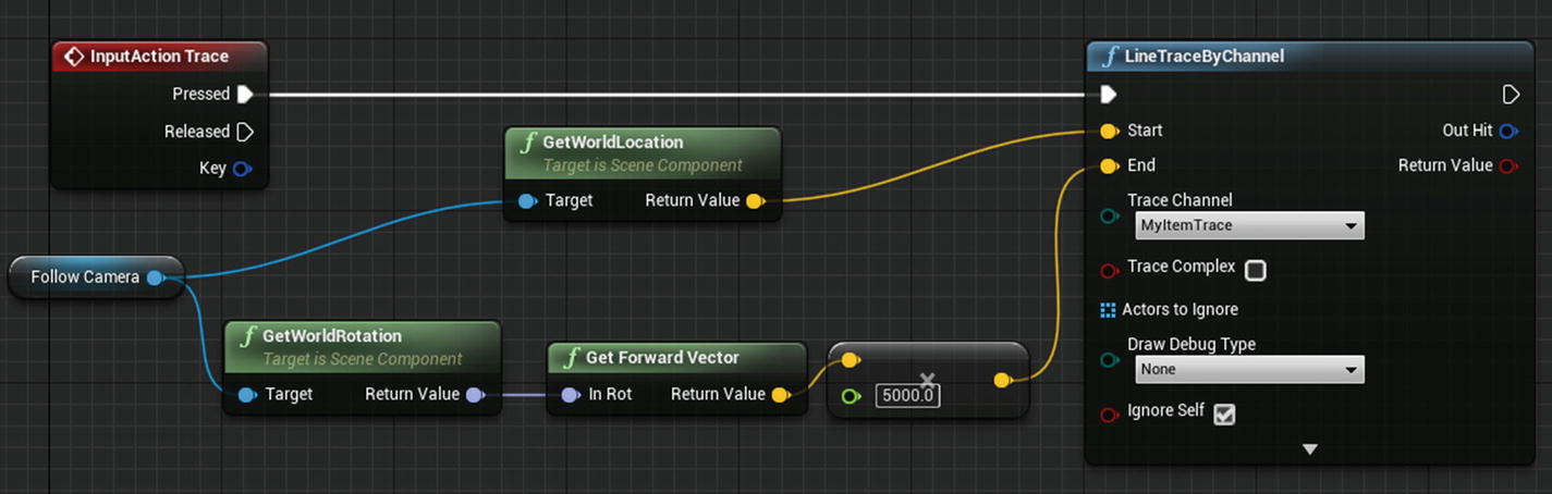
Setting up line trace end location

You are not completely done, but you did finish the trace setup. If you play the game now and press E (or the key you used for Trace), it might appear that nothing is happening, but you are tracing. To check this, click the None drop-down button at Draw Debug Type and change it to For Duration. Press the Play button again and start the tracing. You now see a red line originating from your Camera that shoots toward where you are looking.

Even though you finished the trace, you are still not using any information from the hit result. Let’s fix that. Drag a pin from the red Return Value of the Line Trace, search, and select Branch node. The return value is a boolean (either true or false). It is true if the hit is successful (if it hits any object with MyItemTrace, trace response is blocking; in our case, it is the Blueprint actor we created). It is false if the trace didn’t hit anything. Drag another wire from the Out Hit node and select Break Hit Result. The resulting node is called a Struct node, which is a container containing other data types.

In the Break Hit Result node, click the downward arrow to expand the node and show all the advanced types. Right-click the event graph, and search for and select Print String, which is a simple node that prints a message to the screen. Drag a wire from Hit Actor and connect it to In String of Print String. This automatically creates a new node between Print String and the Struct node. Finally, connect the Branch node with Print String, and you have a complete setup (see Figure 5-15).
../images/496849_1_En_5_Chapter/496849_1_En_5_Fig15_HTML.jpg
Figure 5-15.

Adding debug setup with Print Node

Since you need the trace to react, you must place the Blueprint you created. Drag and drop the Blueprint from the Content Browser to the game world. Now press Play and look at the item placed in the world. Press your Trace input key. You see a red trace line (if you set the Draw Debug Type to For Duration or Persistent) hitting the item and a message printed on the screen (see Figure 5-16).
../images/496849_1_En_5_Chapter/496849_1_En_5_Fig16_HTML.jpg
Figure 5-16.

Print node outputs correct information

Destruction Using Physics

In this section, you use the Apex destruction plugin to create a destructible mesh and interact with it in the game. When writing this book, Unreal Engine was making the transition from Physx to Chaos Physics System, rendering this section obsolete in the future. I don’t cover Chaos because it is not production-ready and requires the GitHub source version instead of the launcher version.

To create a destructible mesh, you first need to enable the Apex plugin from the Plugins section. Click the Edit button in the menu bar and select Plugins. Go to the Physics category and enable Apex Destruction Plugin. Restart the Editor (see Figure 5-17).
../images/496849_1_En_5_Chapter/496849_1_En_5_Fig17_HTML.jpg
Figure 5-17.

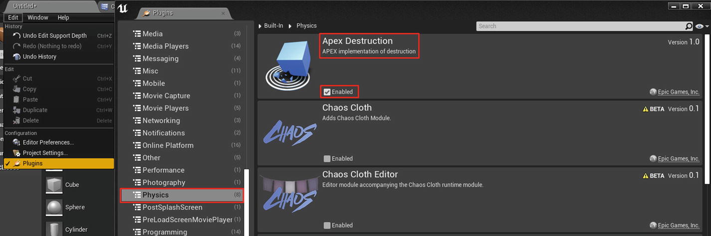
Enabling Apex Destruction plugin

After the restart, you can right-click any Static Mesh actor (or 1M_Cube in our case) in the Content Browser and select Create Destructible Mesh. A new Destructible Editor opens and a new Destructible Editor actor is available next to the static mesh. Let’s go through the basics of Destructible Mesh Editor in Figure 5-18.
../images/496849_1_En_5_Chapter/496849_1_En_5_Fig18_HTML.jpg
Figure 5-18.

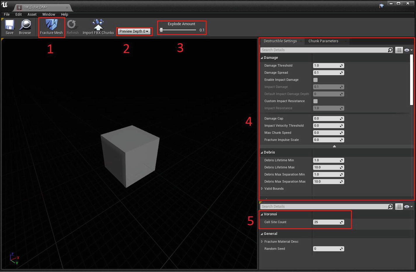
Destructible Editor layout

  • Fracture Mesh (area 1 in Figure 5-18) fractures the mesh into multiple chunks. The number of chunks is based on the Cell Site Count under the Voronoi section (bottom-right corner).

  • Preview Depth 0 (area 2 in Figure 5-18) is the chunk depth.

  • Explode Amount (area 3 in Figure 5-18) is a slider that moves the fractured pieces apart.

  • Destructible Settings (area 4 in Figure 5-18) is the panel where you adjust various destructible settings.

  • Fracture settings (area 5 in Figure 5-18) is the area where you decide the number of chunks to generate.

First, set the Cell Site Count to 100 and press the Fracture Mesh button. This breaks the mesh into 100 different chunk pieces (see Figure 5-19).
../images/496849_1_En_5_Chapter/496849_1_En_5_Fig19_HTML.jpg
Figure 5-19.

100 pieces of mesh

Go back to the Content Browser and drag the newly created Destructible Mesh actor (1M_Cube_DM) to the game world. If you press the Play button now, nothing happens because the destructible mesh is not simulating physics. To fix it, select the Destructible actor in the viewport, and in the Details panel, enable Simulate Physics (see Figure 5-20).
../images/496849_1_En_5_Chapter/496849_1_En_5_Fig20_HTML.jpg
Figure 5-20.

Simulate Physics enabled

Now, if you press Play, you see the destructible mesh falling and hitting the ground, but there is no destruction. Why? This is destructible mesh, but there is no destruction, right? Well, this is because you haven’t enabled damage to destruction mesh yet. So how do you do that? Open the Destructible Mesh actor and turn on Enable Impact Damage (see Figure 5-21).
../images/496849_1_En_5_Chapter/496849_1_En_5_Fig21_HTML.jpg
Figure 5-21.

Impact Damage enabled

Go back to your game world and press Play. Watch how the mesh falls and breaks into pieces (see Figure 5-22).
../images/496849_1_En_5_Chapter/496849_1_En_5_Fig22_HTML.jpg
Figure 5-22.

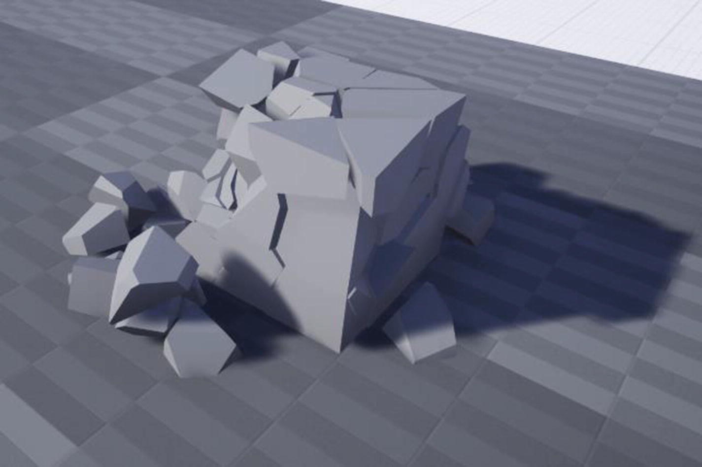
Broken mesh after falling

Let's spice this up a little bit by applying a particle effect when the mesh breaks. For the particle system, add the Starter Content pack if not added yet. To add starter content, click the Add New button in the Content Browser and select the first Add Feature or Content Pack. In the next dialog window, switch to the Content Packs tab, select Starter Content, and click +Add to Project (see Figure 5-23).
../images/496849_1_En_5_Chapter/496849_1_En_5_Fig23_HTML.jpg
Figure 5-23.

Adding Starter Content to our project

After the Starter Content is added, open the 1M_Cube_DM, and in the Destruction Settings Details panel under the Effects category, expand Fracture Settings. Here you see two numbers: 0 and 1. Expand 1 and assign P_Smoke (which is the particle from Starter Content) (see Figure 5-24).
../images/496849_1_En_5_Chapter/496849_1_En_5_Fig24_HTML.jpg
Figure 5-24.

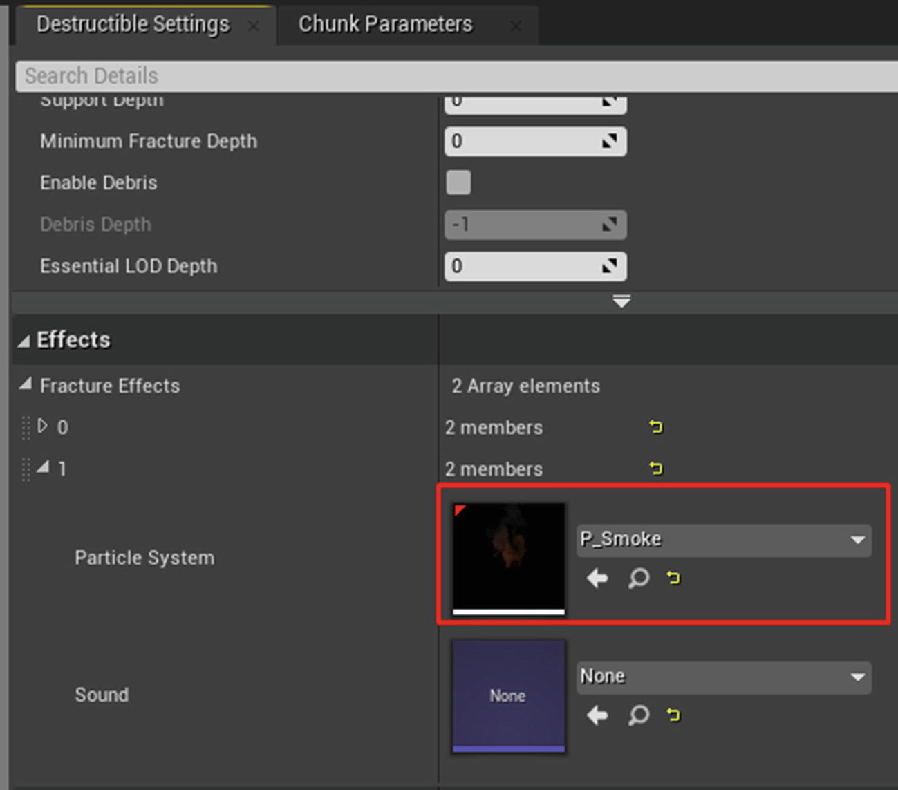
Assigning smoke particle system

If you play now, when the object falls and breaks, you see the particle effect playing at the fracture location (see Figure 5-25).
../images/496849_1_En_5_Chapter/496849_1_En_5_Fig25_HTML.jpg
Figure 5-25.

Smoke effect being played after mesh breaks

..................Content has been hidden....................

You can't read the all page of ebook, please click here login for view all page.
Reset
3.15.4.244