

Photography by Marc de Vinck
MINI FUME EXTRACTOR
Candy tin device helps keep your air clean and your lungs healthy.
By Marc de Vinck

A fume extractor uses an activated carbon filter and fan to remove the smoke, and noxious fumes, created from soldering. The average price of a small hobby version is about $100, but this one will run you more like $10. This mini fume extractor won’t be as effective as a larger one, but it’s definitely better than nothing, and extremely portable. Remember, always work in a well-ventilated area.
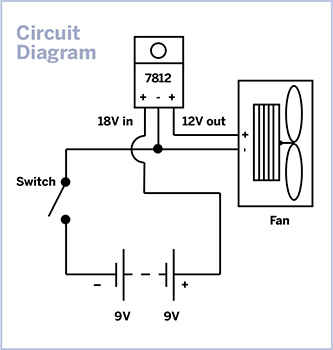
1. Build the circuit.
I decided a quick mock-up might be a good idea, and I’m glad I did. At first, I thought that running the case fan off just one 9-volt battery would provide adequate power. In the end I decided that 12 volts “sucked” better, and in this case that’s a good thing.
The final circuit (at right) uses a simple switch, two 9-volt batteries, a 40mm case fan, and a 7812 voltage regulator. The 7812 takes voltage from the 9V batteries wired in series and steps the voltage down from 18V to 12V, which is what the fan requires.
MATERIALS
7812 voltage regulator IC
Candy tin
Switch, SPST (single pole, single throw)
Case fan, 40mm square
9-volt batteries (2)
9V battery connectors (2) vinyl, not hard plastic
Pieces of screen, 50mm square (2)
Piece of carbon filter cut from a replacement filter
Heat-shrink tubing
Insulated, threaded hook-up wire
Miscellaneous screws and washers
Paint (optional)
TOOLS
Soldering iron
Rosin-core solder
Dremel with cutoff wheel
Drill and small drill bits
Fine-tip marker
Various screwdrivers
Wire cutters
Safety glasses
![]() CAUTION: Wear safety glasses when drilling and cutting metal!
CAUTION: Wear safety glasses when drilling and cutting metal!
2. Solder the components.
Notice the battery connectors (Figure A); they’re the flexible vinyl version, not the hard plastic type. This allows both batteries to fit in the case. The vinyl snaps are only minimally smaller, but it’s enough to make the difference.

Fig. A: Vinyl 9-volt connectors are low-profile enough to let everything fit.
This is a very simple circuit. Solder it according to the diagram, making sure to attach the component leads to the 7812 properly (Figure B). Don’t forget to use heat-shrink tubing on all connections; this is in a metal box ... and metal conducts electricity!
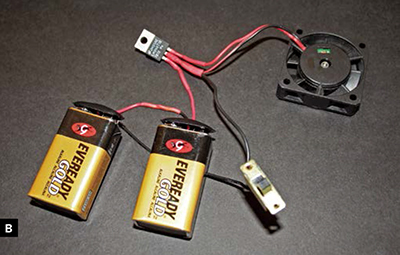
Fig. B: The completed circuit. Make sure to orient the 7812 according to the schematic, and don’t forget to slip on heat-shrink tubing prior to soldering, to insulate all connections from the conductive metal tin.
3. Make sure it all fits.
It’s a snug fit, but you should be able to stuff everything into the tin, packing the batteries side by side next to the fan (Figure C).

4. Cut and drill the holes.
I used a marker and a paper template for the fan openings, making them 35mm square on each side. After you cut the first fan hole, close the box and use the template to align the second hole. You can just “eyeball” the placement. There’s room for error.
Then I marked the opening for the switch and cut all openings with a Dremel tool and cutoff wheel (Figure D).
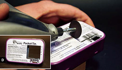
Fig. D: Use light pressure when cutting the openings; let the tool do the work. The openings don’t have to be perfectly aligned.
Next I marked and drilled 2 mounting holes for the switch screws and one for the regulator.
5. Paint and decorate.
I decided to paint the tin this time, unlike my plain RuntyBoost (makezine.com/2008/03/22/making-the-runtyboost). I chose a nice red Krylon paint. I hot-glued a scrap piece of wood to the inside, so I could hold it while I spray-painted it. Two quick coats and I think it looks good (Figure E). Spray paint can be fairly toxic and flammable, so paint outside and away from everything! I’m happy with how it came out, but it definitely needs some graphics to spruce it up. Any suggestions?
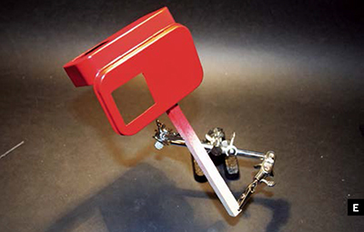
Fig. E: Mount the tin to a wooden stick with hot glue .It can easily be removed, and your hands won’t get all red!
6. Attach the regulator and switch.
First, screw in the 7812 using some washers and a screw to space it slightly away from the side of the tin (Figure F). I used a #6-32 screw and one washer to keep it from the edge, but you can use anything that fits. The screws and washer will also act as a heat sink.
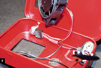
Fig. F: Attach the 7812 and the switch with a few screws.
Finally, screw in the switch.
7. Add the screens and filter.
Here you can see the screen-filter-fan-screen sandwich (Figure G). The screens are 50mm square and the filter is 40mm square. You can buy replacement filters for the commercial extractors at a reasonable price and cut them to size.

Fig. G: Screen, filter, fan, and screen make a nice little sandwich.
Next, just hot-glue or epoxy the corners of the screens to the candy tin, and sandwich the filter and fan in between (Figure H). Compression will ultimately hold it all together. You’re done!
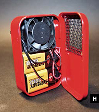
Fig. H: All ready for your next soldering project.
8. Test your extractor.
I’ve run mine continuously for hours and have had no heat buildup from the 7812, and the fan is still running strong (Figure I). It works quite well, and although it’s no replacement for a large fume extractor, it will come in handy for small projects. Remember, follow all safety guidelines when soldering, and work in a well-ventilated room, even if you have a fume extractor.
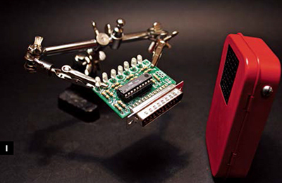
Fig. I: It works great, it’s highly portable, and your lungs will thank you.