
THE MOST USELESS MACHINE
By Brett Coulthard


Photograph by Sam Murphy
PARADOX BOX
Last year I saw a video of the “Leave Me Alone Box” built by Michael Seedman. Flip its switch on, and an arm reaches out of a door to turn the switch back off. That’s what it does, that’s all it does, and it will not stop until its circuit is dead.
I had to have one of my own, so I made one. Seedman’s design uses a microcontroller to run two servomotors: one to open the lid, and another to push the switch. This makes for an impressive performance, but seemed too complicated, and actually, his circuit remains powered even when the box is idle.
For existential purity, I wanted a super-simple machine that really turned itself off. So I came up with a single-motor design controlled by a 555 timer chip, with a curved arm that both lifts the lid and flips off the switch. I called it the “Most Useless Machine” and posted it on Instructables along with a YouTube video of the box in action. The project soon went viral, attracting millions of viewers, thousands of comments, and many builds and design variations. Whew!
Along the way, Instructables member Compukidmike came up with an even simpler version that dispenses with the 555 circuitry entirely by using a gearmotor and two switches. The resulting project, presented here, is the ultimate in technology for its own sake, a minimal assemblage of parts that, through its one meaningless act of defiance, speaks volumes.
Brett Coulthard (frivolousengineering.com) has a short attention span, which explains his varied interests. He lives and pushes buttons near Moose Jaw, Saskatchewan.
The Most Useless Machine has a toggle switch, a motor, and a micro lever switch. The toggle runs the motor forward or backward, depending on which way it’s flipped. Running forward, the motor swings a wooden arm that flips the toggle switch the other way. The motor then runs backward, and as the wooden arm returns to its original resting position, it triggers the lever switch to cut the power off.
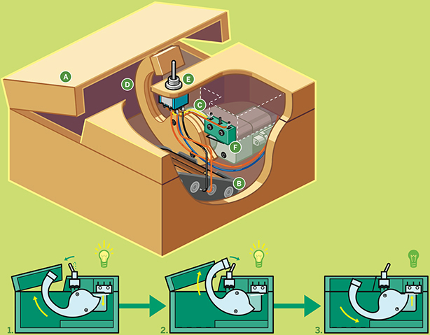
Illustration by Rob Nance

SUICIDE-BOT 3000
BONUS:
Download this custom design and stencil by Rob Nance for your useless machine at makezine.com/projects/the-most-useless-machine
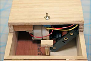
The plain-looking box ![]() has a hinged lid and a toggle switch on the outside.
has a hinged lid and a toggle switch on the outside.
Inside the box, a 4×AA battery pack ![]() powers the motor.
powers the motor.
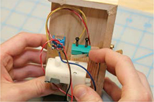
The motor ![]() is a gearmotor whose built-in gearing gives its small DC motor enough torque to move a wooden arm.
is a gearmotor whose built-in gearing gives its small DC motor enough torque to move a wooden arm.
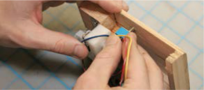
When the motor runs forward, the curved wooden arm ![]() swings up, pushes open the lid, and knocks into the toggle, switching it the other way.
swings up, pushes open the lid, and knocks into the toggle, switching it the other way.
The toggle switch ![]() is a double-pole double-throw (DPDT) switch that’s wired to feed power to run the motor forward or backward, depending on how it’s switched.
is a double-pole double-throw (DPDT) switch that’s wired to feed power to run the motor forward or backward, depending on how it’s switched.
The micro lever switch ![]() , located under the wooden arm, is a single-pole double-throw (SPDT) switch. It’s wired from its normally closed (NC) pin to cut the motor-backward power when the wooden arm pushes down on its lever.
, located under the wooden arm, is a single-pole double-throw (SPDT) switch. It’s wired from its normally closed (NC) pin to cut the motor-backward power when the wooden arm pushes down on its lever.
CONTROL SEQUENCE:
1. When the machine is idle, the circuitry is fully powered down. The toggle switch is in its “off” position. Inside, the lever switch is held down in its “off” position by the wooden arm.
2. When a person flips the toggle switch “on” (forward), it powers the servo to rotate the arm into the toggle switch and flip it back “off” (reverse).
3. Once the toggle switch is flipped “off,” the servo moves in reverse until the arm rests on the lever switch, which is the real “off” switch. This shuts the motor off again.
SET UP.
Photograph by Ed Troxell
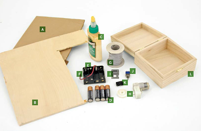
MATERIALS
[A] Heavy paper, card stock, or scrap cardboard
[B] ¼" plywood scrap about the same size as one side of the wooden box [L]
[C] Wood glue or cyanoacrylate gel glue or other good permanent glue for wood and plastic
[D] AA alkaline batteries (4)
[E] 4xAA battery holder Digi-Key #BH24AAW-ND (digikey.com) or RadioShack
[F] Insulated solid-core wire, 24-gauge, different colors Scavenge from dead telephone cable, Ethernet cables, thermostat wire, intercom cable, and anything with tiny colored wires. You can’t have too many different colors of wire.
[G] Insulated, stranded hookup wire, 22-gauge or thereabouts
[H] Gearmotor Pololu Robotics & Electronics (pololu.com) plastic gearmotor: part #1118 or #1119 (the latter is slower but stronger)
[I] Gearmotor mount and mounting bracket Pololu stamped aluminum L-bracket pair, part #2670
[J] DPDT toggle switch Digi-Key #EG2407-ND, RadioShack #275-636, or salvage this and the micro switch from common electronics.
[K] SPDT lever micro switch Digi-Key #EG4544-ND or RadioShack #275-016
[L] Small wooden box with lid large enough to fit the battery pack, motor, and arm in resting position (down). The one I used was purchased at a Dollar Giant store. If your lid isn’t hinged, you’ll also need some small hinges.
TOOLS
Table saw or handsaw that can cut wood straight
Miter box (optional) but helpful for handsaw straight cuts
Jigsaw, coping saw, or scroll saw or other saw that can cut curved wooden pieces
Pencil and eraser
Ruler
Scissors
File and sandpaper
Drill and drill bits: 1/16", ¼"
Small screwdriver for hinge and motor mounting screws
Soldering iron
Wire strippers
Side cutter
Hobby knife
Glue gun and hot glue
MAKE IT.

BUILD YOUR USELESS MACHINE
Time: An Afternoon Complexity: Easy
START ≫
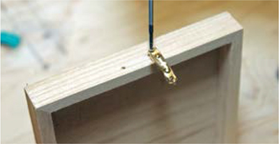
1. PREPARE THE BOX
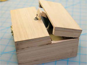
One half of the lid hinges up, while the other half carries all of the machine’s workings. The workings all mount onto the same piece so that they’ll stay aligned.
1a. Remove any latches and hinges on the box’s lid.
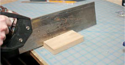
1b. Cut the lid approximately in half through the middle crosswise, undercutting at a slight angle so that the hinged half won’t bind when opening. (You can see this undercut in Step 2c or the overview illustration on page 294.) Before you cut, make sure the machine half has at least enough space to fit both the motor and the micro switch lined up lengthwise.
2. DETERMINE THE LAYOUT
2a. Use the pencil to draw scale paper templates of the motor, toggle switch, micro switch, and the machine half of the lid, all in side-view, and cut them out. Also cut a template for the motor’s mounting wheel or horn, and mark the axle on both the motor and mount templates.

Photography by Ed Troxell
2b. Use the component templates to figure out the shape of the arm and how everything should attach to the lid. Download sample templates at makezine.com/projects/the-most-useless-machine. You want the back of the arm (or a mounting horn) to push against the lever switch when it’s retracted. Then the arm should rotate and clear the lid while its “hand” swings over and pushes the toggle switch.
Cut templates for the arm and for a standoff bracket that holds the motor and the lever switch. Refine their shapes and sizes and move the pieces of paper around until you’re sure that they all work together, while still leaving room for wire connections.

2c. Mark the positions on the templates where they meet: the toggle and bracket’s position on the lid, and the motor and switch’s position on the bracket.
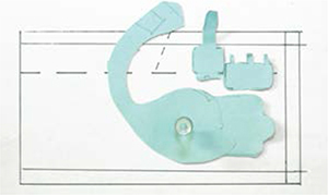
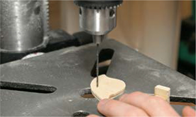
2d. Trace the template shapes onto ¼" plywood and cut the pieces out. File and sand the edges smooth.

2e. Mount the arm to the motor’s mounting wheel or servo horn. Drill 1/16" pilot holes in the arm and mount it with small screws (usually included).
2f. Measure and mark a centerline across the machine half of the lid, perpendicular to its cut end. Then mark the toggle’s distance along this line, following its position marked on the templates.

3. BUILD THE CIRCUIT
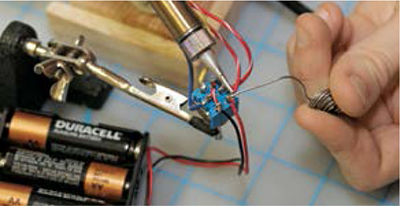
3a. Now it’s time to fire up the soldering iron. If your motor already has leads attached, solder them to each of the 2 middle legs of the toggle switch. Otherwise, cut, strip, and solder wire leads between each motor terminal and the middle toggle pins; 4" long is plenty for all connections in this circuit, and you may want to shorten them later for neatness.

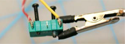
3b. Solder a short jumper wire diagonally between 2 opposite corner legs of the toggle switch, then solder separate leads to the remaining 2 legs at the other corners.

3c. Solder the 2 free leads from the toggle to the lever switch. Connect one to the common tab (marked C), closest to the lever’s pivot. Connect the other lead to the normally closed (NC) leg, farthest from the pivot. Don’t connect anything to the normally open (NO) tab in the middle.
3d. Solder the battery pack’s leads to the 2 legs at either end of the toggle. The circuit is complete! Test it by loading batteries into the pack. The motor should run, the toggle should reverse its direction, and the lever switch should shut it off in one direction. If it all checks out, remove the batteries, leave the toggle thrown in the direction that the lever interrupts, and mark or note this direction on the motor.
4. ASSEMBLE AND ADJUST
4a. Drill a ¼" hole in the machine side of the lid, at the toggle position you marked in Step 2f.

4b. Fit the toggle switch up through the hole, positioned with the toggle thrown in the direction opposite the lid cut. Don’t glue it in yet.
4c. Hold the wooden bracket, motor, and lever switch in place against the lid so that they align properly with each other and with the toggle. Mark their positions with the pencil.
If the motor turns in the opposite direction from what you anticipated while determining the layout (if the interruptible direction turns the arm out, not in) you should reverse the connections to the motor, or else position the motor the other way and arrange the pieces in mirror-image on the opposite side of the box.
4d. Temporarily hold all the pieces in place with a bit of hot glue. Put the lid on the box with the other half off, load the batteries, and check to see that everything works perfectly (which is unlikely).
4e. Tweak the components’ placement and the shape of the arm as needed, ungluing and regluing with hot glue, until everything does what it should. You may need to file down part of the arm so it clears the bottom of the box, or fine-tune the position of the all-important micro lever switch.
When everything checks out, mark the final locations. Then mount the motor to the bracket with its included screws and attach the other components in place with permanent glue.

4f. For the other half of the lid, replace (or install) the hinges on the narrow end opposite the machine half, drilling 1/16" pilot holes.

4g. At this point, you should have a fully functioning Useless Machine. Don’t wear it out!
FINISH X
NOW GO USE IT »
USE IT.
LEAVE ME ALONE ALREADY
CUSTOMIZED USELESSNESS
The Most Useless Machine, like Claude Shannon’s original, is a desktop or tabletop conversation piece. I went with a minimal aesthetic that leaves it most open to interpretation, but you can dress it up by labeling the switch positions, using a recognizable object like a doll’s arm for the arm, or otherwise decorating it.
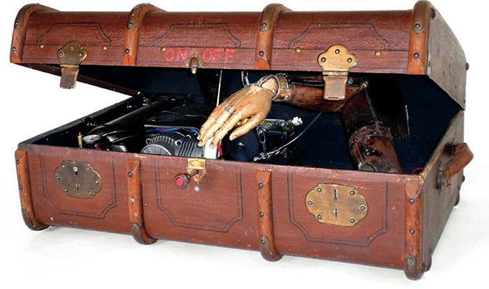
On a much larger scale, Swiss artist HannsMartin Wagner built a version that used an old wooden trunk as a box, a weathered prosthetic arm, and an air compressor for power (see below).
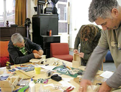
I was amazed at the response to my original Instructable. Everyone wants one of these boxes, and wants to share details of their own build! Its social appeal was also shown this past spring, when the Birmingham, U.K., hackerspace FizzPop (www.fizzpop.org.uk) hosted a Useless Machine-making workshop led by Nikki Pugh (at right).
![]() For part templates, videos of the Most Useless Machine in action, alternate versions, how-to videos, and other resources, visit makezine.com/projects/the-most-useless-machine.
For part templates, videos of the Most Useless Machine in action, alternate versions, how-to videos, and other resources, visit makezine.com/projects/the-most-useless-machine.
Photography by Nikki Pugh (top); and Hanns-Martin Wagner/www.sinnwerkstatt.ch (bottom)