
SOUS VIDE IMMERSION COOKER
By Scott Heimendinger

Photography by Scott Heimendinger
PRECISION GOURMET
I’m fascinated by sous vide cooking, in which foods vacuum-sealed in plastic are immersed in a precisely temperature- controlled hot water bath to achieve optimal doneness.
But most sous vide (soo-veed) cooking machines are commercial models that cost north of $2,000, and the first “home” version, the countertop SousVide Supreme, is priced in the neighborhood of $450 (not including vacuum sealer), which is still a steep investment for something that essentially keeps water warm.
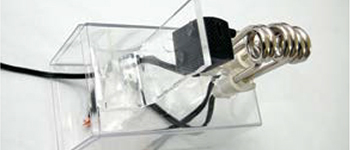
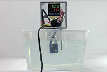
I decided to build a better device on the cheap. Behold, the $75 DIY Sous Vide Heating Immersion Circulator! By scrapping together parts from eBay and Amazon, I created a portable device that heats and circulates water while maintaining a temperature accurate within 0.1°C. And unlike the SousVide Supreme, it mounts easily onto larger containers, up to about 15 gallons, for greater cooking capacity.
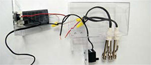
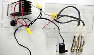
The water is heated by three small immersion heaters and circulated by an aquarium pump to keep the temperature uniform. An industrial process temperature module controls the heaters, and an eye bolt lets you clamp the entire apparatus to the rim of a plastic tub or other container.
To cook sous vide, you also need a vacuum sealer, which this project does not include. I bought a good one new for about $112.
Cooking sous vide (“under vacuum” in French) means vacuum-sealing ingredients in plastic and immersing them in a relatively low-temperature bath (typically around 140°F/60°C) for long periods of time. The process retains cell structure and juices that foods lose through other cooking methods.
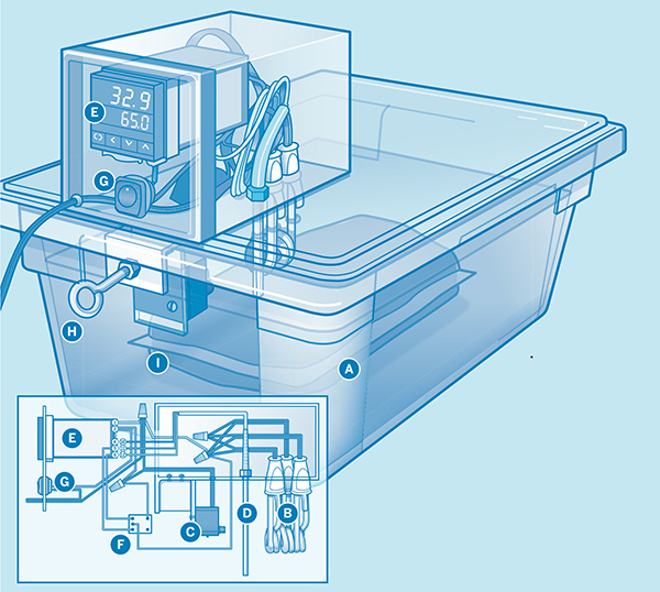
Illustration by Damien Scogin
![]() A container holds the hot water bath that cooks the food.
A container holds the hot water bath that cooks the food.
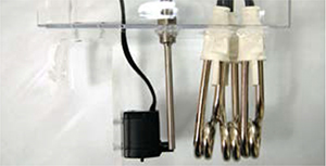
![]() Three immersion heaters heat the water.
Three immersion heaters heat the water.
![]() An aquarium pump circulates the water while the heaters are on, to keep the temperature distribution uniform.
An aquarium pump circulates the water while the heaters are on, to keep the temperature distribution uniform.
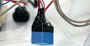
![]() A thermocouple probe reads the water temperature.
A thermocouple probe reads the water temperature.
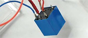
![]() The PID controller runs a proportional-integral-derivative (PID) algorithm that monitors the water temperature and switches the immersion heaters on and off to keep it constant.
The PID controller runs a proportional-integral-derivative (PID) algorithm that monitors the water temperature and switches the immersion heaters on and off to keep it constant.
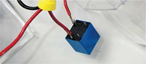
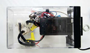
![]() A relay converts 12V DC switching from the PID controller into 120V AC switching for the heaters.
A relay converts 12V DC switching from the PID controller into 120V AC switching for the heaters.
![]() A rocker switch turns the entire unit on and off.
A rocker switch turns the entire unit on and off.
![]() An eye bolt clamps the unit to the side of the container.
An eye bolt clamps the unit to the side of the container.
![]() A vacuum bag acts as a thermally conductive but waterproof barrier between the food and the water bath.
A vacuum bag acts as a thermally conductive but waterproof barrier between the food and the water bath.
A PID temperature controller is like an advanced thermostat. Regular thermostats click on and off when the measured temperature passes fixed thresholds, and the resulting temperature oscillates around the thresholds. This creates an opportunity for temperature “carry-over” in the food, like the way meat’s internal temperature can rise after you take it out of the oven.
In contrast, PID controllers use the PID algorithm, common in industrial control applications, to track temperature changes and calculate how much ON time will raise the measured temperature (the process variable) to the target (the set point) asymptotically, rather than overshooting it.
By predicting, mathematically, the impact that turning on the heaters for 1 second will have on overall water temperature, the PID controller enables extremely precise temperature control and stability over long periods of time.
NOTE: Be aware of a minor technical nuance — the model CD101 PID controller used in this project is accurate when used in Celsius mode. For unknown reasons, people have experienced inaccurate readings and fluctuating temperatures when the controller is set to Fahrenheit.
SET UP.
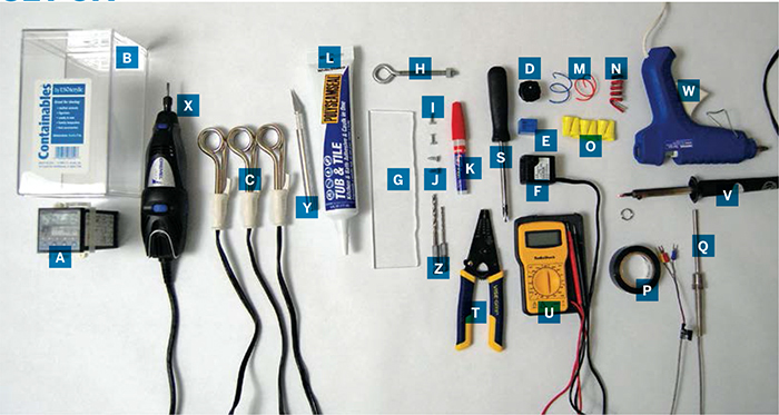
MATERIALS
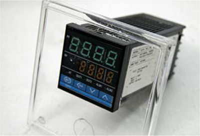
[A] Digital PID temperature controller, model CD101 with PT100 support and voltage pulse output Some model CD101 units will not work; you need to make sure that the 5th character of its code (on a sticker on the side) is V, for voltage pulse output. I bought mine (code FK02-VM*AN-NN) for $39 from eBay, or see Sure Electronics #RDC-TE11113 (sureelectronics.com).
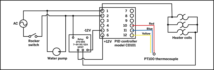
This controller has 12 screw terminals. Posts 1 and 2 connect to AC power, 5 and 6 control a relay for the heater, and 10–12 connect to a thermocouple. If you use a different controller, refer to its datasheet for the functionally equivalent connection locations.
[B] Clear acrylic storage container, 7"×4"×4" item #B000NE80GO from Amazon (amazon.com)
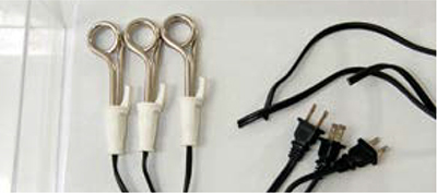
[C] Immersion heaters, Norpro 559 (3) Amazon #B000I8VE68
[D] SPST rocker switch, heavy duty rated 10 amps at 125VAC or 250VAC, mounts in ¾"-diam. hole
[E] SPDT mini relay, 7V–9V DC, 12A RadioShack #275-005. You may want to upgrade to a solid-state relay for a more robust,reliable build. The wiring is the same for an SSR as it is for the relay included in the build instructions. A good option is Lightobject #ESSR-25DAC.
[F] Aquarium pump with suction cup “feet” Catalina Aquarium #A801 (catalinaaquarium.com)
[G] Clear acrylic sheet (plexiglass), 7"×2"×¼" thick From hardware stores or online vendors; you may have to cut it to size with a band saw, table saw, fine-toothed hacksaw, or jigsaw.
[H] Eye bolt, ¼"×2", with nut
[I] Machine screws, #4-40, ½" long, stainless steel, with matching nuts (2)
[J] Sheet metal screws, #6-40, 3/8" long, stainless steel (2)
[K] Super glue
[L] Waterproof silicone caulk aka tub and tile caulk
[M] Wire, 22 gauge, stranded, 1'
[N] Wire, 14 gauge, solid core, 4'
[O] Wire nuts, large (4)
[P] Electrical tape
[Q] Thermocouple temperature sensor probe with 3 leads #PT100 from Virtual Village (virtualvillage.com), or from eBay.
[NOT SHOWN]
Large, straight-sided container to hold the water. Because the bath doesn’t get very hot or touch the food, plastic is OK; I use a 17qt plastic storage bin I bought at Bed Bath & Beyond (bedbathandbeyond.com).
TOOLS
[S] Phillips screwdriver
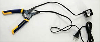
[T] Wire cutters and strippers
[U] Multimeter
[V] Soldering iron and solder
[W] Hot glue gun
[X] Rotary cutting tool with router bit such as a Dremel
[Y] Hobby knife
[Z] Drill and drill bits: 1/3", 5/32"
[NOT SHOWN]
CNC laser cutter (optional)
Marker
Stove and oven mitt
Bowl of cold water
MAKE IT.
BUILD YOUR SOUS VIDE IMMERSION COOKER
Time: 6 Hours Over 2 Days Complexity: Easy
START≫
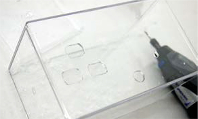
1. CUT THE ACRYLIC ENCLOSURE
This is the most difficult part of the project. For your cooker to be sturdy, water-resistant, and decent looking, the mounting holes must be cut precisely. I used a CNC laser cutter I have access to at work, but with a steady hand you can achieve the same results using a rotary tool like a Dremel.
1a. Download and print the cutting template in Cutouts.pdf from makezine.com/projects/sous-vide-immersion-cooker. This template matches the heaters, controller, and switches I used, so you’ll need to adjust the shapes and sizes if you use different parts.
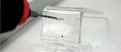
1b. Following the template, cut out the 3 holes for the immersion heaters on one side of the acrylic container, near its base.
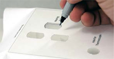
1c. Mark and cut the small oval-shaped hole for the water pump power cord and a circular hole for the thermocouple.
1d. Follow page 2 of the template to mark and cut openings in the lid of the container for the controller, switch, and power cord.
2. MOUNT THE IMMERSION HEATERS
2a. Cut the power cord off each heater, leaving an 8" tail of wires from each coil end.
2b. Using your hobby knife, scrape the flat sides of the heater handles to remove the lettering and flatten the circular rim where it meets the cord.

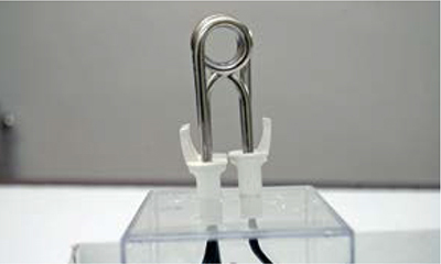
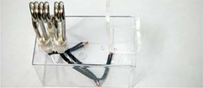
2c. Fit all 3 heaters into their holes in the container, such that the coils stick out and line up. Your finger should be able to fit through all 3 coils at once. Trim the holes if needed to make the heater handles fit snugly.
2d. Caulk a fully waterproof seal around the heater handles on the outside of the enclosure and let dry overnight.

For added strength, add hot glue over the caulk after it’s dried. The hot glue only needs 5 minutes to dry before continuing.
3. ATTACH THE MOUNTING BRACKET
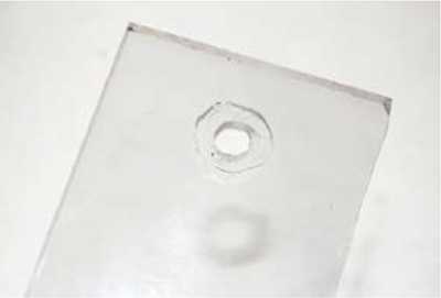
3a. Cut a 7"×2" rectangle out of ¼" acrylic. The cut sides don’t have to be perfect as long as the rectangle dimensions are approximate. Use a rotary cutter to rout a shallow recess that’s the same shape and size as the nut for your eye bolt, centered at one end, as shown on page 3 of the template. Drill a ¼" hole through the center of the recess for the eye bolt to pass through.
3b. It’s time to bend the acrylic sheet. Clear a countertop near your stove, put a bowl of cold water within reach, and mark the bend point lines from the template onto the acrylic.
NOTE: If your countertop is too thick or thin for this process, you’ll need to bend the sheet around a hard, stable object, approximately 2" thick, such as a 2×4.
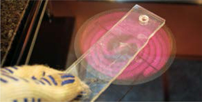
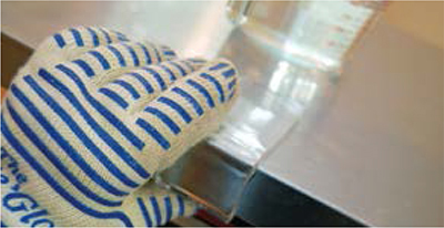
Turn one of the front burners on high, hold the undrilled end of the acrylic with an oven mitt, and place the drilled end with bend lines a few inches above the burner, moving the acrylic around and turning it to heat both sides. If it begins to form small bubbles, move it away from the heat a little. When the acrylic starts to curl away from the heat, it’s ready to bend.
3c. With the recess for the nut facing outward, bend the acrylic around the edge of the counter (or other object) approximately along the marked lines to form a “J.” While in place, press the middle segment of the J against the edge of the countertop to make it flat. Immediately drop the acrylic into cool water so that it holds its form.
3d. Position the middle segment of the J bracket against the heater side of the enclosure, with the bracket’s nut side aligned along the enclosure’s rim. This is how you’ll bolt these 2 pieces together. Mark and drill two 1/8" holes through the bracket and 2 matching holes in the enclosure. Check that the 4-40 machine screws fit through both pairs of holes.
3e. Liberally apply super glue to the underside of the bracket, and bolt it to the enclosure with the machine screws and nuts.
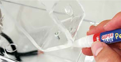
3f. Liberally apply more super glue to the recessed area for the eye bolt nut, and set the nut in place. Reinforce the bond with hot glue, but don’t obstruct the hole in the nut.
For more support, you can cut a 1½" acrylic round with a hole fitting the nut, and glue it to the J-clamp overlapping the opening. This will provide extra gluing surface and take stress off the nut.
4. ATTACH THE PUMP
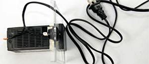
4a. Cut the water pump’s power cord about 8" from the pump. Reserve the severed cord, which will become the cooker’s power cord.
4b. Position the pump on the long side of the bracket, with its cord pointing toward the enclosure and its top aligned with the top of the heater coils. The pump should be placed so its outlet is more or less pointing through the coils. Mark the locations of the suction cup feet on the bracket.
4c. Drill two 5/32" holes through the bracket at the exact centers of the suction cup locations. Check that the holes can accommodate the sheet metal screws, and enlarge them if needed by wiggling the drill bit.
Remove the suction cups from the pump, and attach the pump to the bracket with the sheet metal screws in the suction cup holes.
5. COMPLETE THE WIRING AND ASSEMBLY
For the big picture, refer to this wiring diagram.
![]() CAUTION: Don’t ever power on the heater coils unless they are submerged in water! (They’ll burn out.) And if you’re unfamiliar working with AC power, seek assistance from someone who’s knowledgable.
CAUTION: Don’t ever power on the heater coils unless they are submerged in water! (They’ll burn out.) And if you’re unfamiliar working with AC power, seek assistance from someone who’s knowledgable.
5a. Split the heater cords apart and strip about 2" of shielding away from each end. Twist and solder together 1 lead from each of the heaters, then repeat for the other set of leads to wire the 3 coils in parallel.
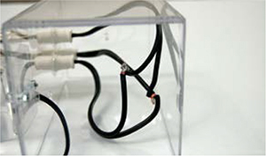
5b. Cut two 18" 14-gauge wires and strip 3/8" of shielding from each end. Use wire nuts to bundle one end of each wire with a set of heater leads. One wire will connect to AC power, and the other will connect to the relay.
5c. Remove the mounting ring from the PID controller, fit its front panel out the opening you cut for it in the acrylic lid, and secure the controller from the back by replacing the mounting ring.
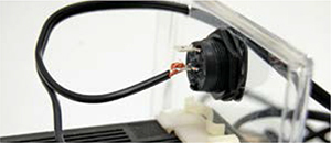
5d. Fit the power switch into its hole in the acrylic lid and secure it with its included mounting nut. Run the power cord you cut from the water pump through its hole nearby. Separate its leads, strip ¼" of shielding, and solder 1 lead to 1 leg of the power switch.
5e. Cut and strip 3 short (about 4") lengths of 14-gauge wire. Twist-bundle 1 wire with the free power cord lead, 1 lead from the water pump, and 1 of the 14-gauge leads from the heaters. Secure the bundle with a wire nut, and screw the short wire to terminal #1 on the controller.
5f. Solder the other 4" piece of 14-gauge wire to the unconnected leg of the power switch, and then screw the other end to the #2 terminal on the controller.
5g. Make a new bundle connecting the free lead from the water pump, the wire from the #2 terminal, and the third short length of 14-gauge wire.
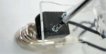
5h. Orient the relay so that its underside (with the pins) faces you, and the row with 3 pins is facing down. Solder the free lead from the previous step to the upper left pin of the relay.
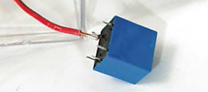
5i. Solder the free lead from the heater bundle to the middle bottom pin of the relay.
5j. Cut and strip two 6" lengths of 22-gauge wire. Solder one to the bottom right pin of the relay and connect it to the #5 terminal on the controller. Solder the other piece to the relay’s bottom left pin and connect it to the #6 terminal.
5k. Insulate and strengthen the relay connections with a liberal application of hot glue. Wrap the relay and wires with electrical tape.
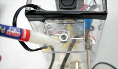
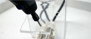
5l. Apply hot glue around the holes for the power cord and water pump cord, to prevent steam or water from leaking into the enclosure.
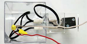
5m. Insert the PT100 thermocouple into its hole in the enclosure and secure with hot glue. Connect its red lead to the controller’s #10 pin, its blue lead to the #11 pin, and the yellow lead to the #12 pin.
5n. Put the acrylic lid on the open end of the container, and apply a neat strip of electrical tape around the edges to hold it on. (Once you’ve verified that the cooker works, you can then glue the seam.) Insert the eye bolt through the nut.
5o. Everything is wired up and assembled. Now you probably want to see if it works. BUT WAIT! Don’t turn the machine on (ever!) unless the coils are submerged in water or else they’ll burn out in about 5 seconds. I learned this the hard way.
5p. Fill a container with enough water to cover the top of the circular part of the heater coils by 1/4"–1/2". Mount the cooker inside with its bracket hanging over the lip, and tighten the eye bolt to secure.
Plug in the cord and flip on the power switch. If the PID controller turns on and the pump starts pumping, that’s a good sign. Note that the heaters may not warm up yet, depending on what the controller’s default target temperature is.
![]() CAUTION: 120V AC current is dangerous and misuse can injure or kill. Seek the assistance of a qualified electrician if needed. Take care to keep the control box and wires out of the water or other liquids. And once you’ve tested your cooker, seal the lid on the control box.
CAUTION: 120V AC current is dangerous and misuse can injure or kill. Seek the assistance of a qualified electrician if needed. Take care to keep the control box and wires out of the water or other liquids. And once you’ve tested your cooker, seal the lid on the control box.
6. PROGRAM THE CONTROLLER AND TEST
For the model CD101 PID controller manual and a full sequence of photos showing how to program it for this project, visit makezine.com/projects/sous-vide-immersion-cooker.
6a. The PID controller defaults to a different thermocouple than the PT100 used here, so you need to reconfigure it for a PT100 sensor. Press and hold the SET button until AL1 appears, then keep pressing SET until you see LCK (lock) with 1000 underneath. To unlock the settings, we need to change this value.
6b. Use the left-arrow key to move the cursor and the up-arrow key to change LCK to 1100. Then press SET again to exit the menu.
6c. Push and hold the SET and left-arrow keys together until you see COD (code). Use the arrow keys as before to set this value to 0000, then press SET again to see SL1, the sensor type symbol.
6d. Change SL1 to 1100, for the PT100 sensor. Press and hold the SET and left-arrow keys again to exit. Then re-lock the settings by setting the value of LCK back to 1000, as in Steps 6a–6b.
6e. It’s time to heat things up. The top line of the display (green) shows the current temperature, and the second line (orange) shows the target. Set a target temp by tapping the SET button, using the up and down arrows to specify the target, and pressing SET again to confirm. 50°C is good for testing.

If all’s well, the OUT1 light will turn on and you’ll hear a soft clicking as the relay turns on the heaters. The temperature reading will increase, and you’ll hear more frequent clicking as it approaches the target.
NOW GO USE IT ≫
FINISH X
USE IT.

MAKE THE ULTIMATE STEAK ’N’ EGGS
VACUUM SEALING
A good vacuum seal is essential to sous vide. Without air pockets, the heat transfers into the food evenly and efficiently. A good seal also dramatically decreases the risk of bacterial contamination from long incubation at low temperatures.
I use a FoodSaver V3835, which I bought for just over $100 with a 20% coupon at Bed Bath & Beyond. It uses rolls of plastic, so you can make the bags any size you need. I recommend against using cheaper handheld sealers. I’ve tried a few and had problems creating a reliable seal.
With any sealer, always wipe clean and dry the end you’re going to seal, or the plastic layers might not melt together properly.
Using a zip-lock bag instead of a vacuum sealer is actually OK for cooking times up to 4 hours, but also riskier for leaking and contamination.
KITCHEN TESTS
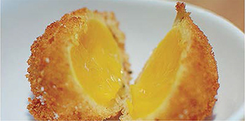
To reveal the power of sous vide, cook an egg in the shell (no plastic needed) at 64.5°C for 1 hour. This yields an amazing transformation: perfectly soft whites, not runny or rubbery, and a yolk with the consistency of a rich pudding. It’s impossible to achieve this through any other cooking method, and it’s spectacular the first time you experience it.
I expanded on this amazing transformation by breading the yolks and quickly deep-frying them to add a crunchy shell. See my recipe at makezine.com/projects/sous-vide-immersion-cooker.
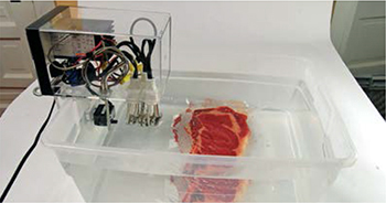
Next, try cooking a good, thick steak. Unlike conventional cooking methods, sous vide gives you a perfect medium-rare steak all the way through. To finish the steak, pat all sides dry and sear like crazy with a propane torch (the kind plumbers use).
Some things that don’t work well sous vide, in my experience, are broccoli, kiwi, and strong aromatics. Note also that if you sous vide with too much garlic, your whole house will smell like feet.
GENERAL-PURPOSE TEMP CONTROLLER MOD
Several people have modified this project so that the relay switches a power outlet that the heaters and pump plug into, and the probe plugs into an added jack. Then, if a heater burns out, you plug in another one rather than having to mess with glue and solder. Modularizing the control and power components this way also lets the machine double as a precise temperature controller for a smoker box, such as Alton Brown’s DIY flower-pot smoker (see makezine.com/projects/sous-vide-immersion-cooker). You just plug in the hotplate filled with wood chips.
Pick up a few steaks and break out your blow torch — it’s time to start cooking like a geek!
![]() For hole templates, the CD101 PID controller programming instructions and manual, Scott’s Deep-Fried Sous Vide Egg Yolks recipe, and other resources, visit makezine.com/projects/sous-vide-immersion-cooker.
For hole templates, the CD101 PID controller programming instructions and manual, Scott’s Deep-Fried Sous Vide Egg Yolks recipe, and other resources, visit makezine.com/projects/sous-vide-immersion-cooker.