
SKILL BUILDER
Electronics: Fun & Fundamentals
EASY
THE ECLECTIC
ELECTRET MICROPHONE
Written and photographed by Charles Platt
Time Required: 1 Hour Cost: $10–$20
THE MICROPHONES IN OLD-FASHIONED WIRED TELEPHONES were relatively heavy, large, and expensive, and their sound quality was terrible. Thanks to materials science developments in the 1990s, electrets are now tiny, high- quality, and available from some sources for less than $1 each.
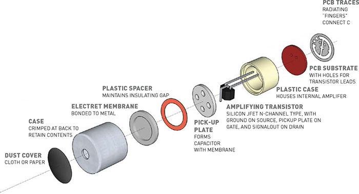
The electret microphone performs its magic with a pair of thin electrostatically charged membranes. When sound waves force one closer to the other, a tiny transistor in the microphone amplifies the fluctuations in electrical potential. We can amplify them further, in our circuits, and use them for many purposes.
MATERIALS
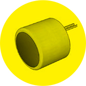
» Electret microphone Most 8mm or 10mm electrets will work in this circuit.
» Ceramic capacitors: 0.1μF (2), 0.68μF, 10μF (2)
» Electrolytic capacitor, 330μF
» Resistors: 22Ω, 1K (2), 1.5K, 3.3K, 10K, 100K (2)
» Trimmer potentiometers: 10K, 100K
» Integrated circuits: LM741, LM386 Manufacturers may precede these generic part numbers with additional letters or numbers.
» Loudspeaker: 2-inch or 3-inch, 50Ω–100Ω
» 9V batteries (2) and connection clips
Testing, Testing ...
Most electrets have two terminals. They may have leads attached or just solder pads for surface-mount applications. Since the pads are reasonably large, you can easily add your own leads if necessary.
Your first step is to distinguish the positive and negative terminals. They are not usually marked in any way, and the datasheets can be surprisingly uninformative. However, if you look at the back of the microphone, you should see metal “fingers” radiating outward to the shell from one of the terminals (Figure A). These “fingers” — embedded in a translucent sealing compound — identify the negative side of the electret, which should be connected to ground.
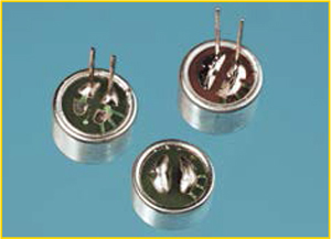
![]() Three electret microphones viewed from below. Upper right: from RadioShack. Upper left: from mouser.com. Bottom: from allelectronics.com. The ground terminal is on the right-hand side in each case.
Three electret microphones viewed from below. Upper right: from RadioShack. Upper left: from mouser.com. Bottom: from allelectronics.com. The ground terminal is on the right-hand side in each case.
Connect the other terminal through a 3.3K series resistor to the positive side of a 9VDC power supply, and you should see the electret responding to sound when you apply a meter (Figure B). Don’t forget to set your meter to measure AC, not DC. A range of 1mV to 40mV is typical.

![]() Detecting the output from an electret microphone.
Detecting the output from an electret microphone.
Amplification
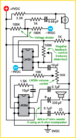
We can use an op-amp to turn millivolts from the electret into volts. Figure C shows a circuit using the LM741. While many simpler circuits exist, this one minimizes oscillations and distortion. The LM741 outputs to an LM386, a basic power amplifier chip that can drive a small loudspeaker.
![]() An audio amplifier circuit.
An audio amplifier circuit.

Basic pinouts of the LM741 op-amp and LM386 power amp. Unlabeled pins have additional functions; see datasheets for details.
 Alternate schematic symbols for an electret microphone.
Notice we use a “split power supply” consisting of +9V DC, –9V DC, and 0V (represented by a ground symbol). To set this up, you can use a pair of 9V batteries in series, as shown in Figure D. But why is it necessary?
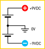
![]() The split power supply required by the circuit can be provided by two 9V batteries wired in series.
The split power supply required by the circuit can be provided by two 9V batteries wired in series.
Consider how sound waves are created. All around us is static air pressure, which can be imagined as an absence of sound. When you speak, you create waves that rise above the ambient level, separated by troughs that drop below it. An amplifier must reproduce these fluctuations accurately, and relatively positive and relatively negative voltages are the most obvious way.
In Figure C, a 0.68μF capacitor couples the microphone through a 1K resistor to the op-amp. The capacitor blocks DC voltage, to stop the op-amp from trying to amplify it. But the capacitor is transparent to the alternating audio signal, which we do want to amplify. The mic signal induces fluctuations in a neutral voltage provided by a voltage divider, and the op-amp amplifies the difference between these fluctuations and a second input, which has a stable reference voltage.
This reference is created with negative feedback from the op-amp output, adjusted with the 100K trimmer. Negative feedback keeps the op-amp under control, so that it creates an accurate copy of the input signal. To learn more signal processing with opamps, look out for Make: More Electronics, the sequel to my book Make: Electronics.
Making It Work
The two-battery split supply has some limitations. The output won’t be loud, and it may be scratchy, especially if your two 9V batteries deliver unequal voltage. Use the 100K trimmer to minimize the distortion and the 10K trimmer to maximize the volume. You’ll get better results if you have a proper split power supply, or two 12V AC adapters connected through separate 9VDC voltage regulators.
A 50Ω-100Ω loudspeaker is preferred. I got really good results when I used alligator clips to connect the output from the circuit to the mini-jack plug on my computer speakers, but if you make a wiring error, you may damage your speakers.
You may be interested in other ideas, such as using sound to switch on a light or start a motor. For this purpose, instead of an audio amplifier such as the LM386, the output from the op-amp can trigger a solid-state relay. Add a 100μF capacitor between the op-amp output and ground to smooth the signal (so that the relay doesn’t “chatter”) and adjust the 100K trimmer until the sensitivity of the circuit is appropriate.
An op-amp can feed its output (through a coupling capacitor) to a microcontroller input pin. You’ll have to discover the digital value that the analog-digital converter inside the microcontroller assigns to various levels of sound, but after that you can program different outputs for different sound levels.
Analog audio circuits can be trickier than digital circuits. Learning how to use an electret is a great introduction! ![]()

CHARLES PLATT is the author of Make: Electronics, an introductory guide for all ages. He has completed a sequel, Make: More Electronics, and is also the author of the Encyclopedia of Electronic Components in three volumes.
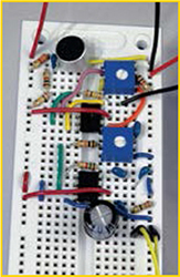
To avoid oscillations and other noise, keep all wires as short as possible, and pack the components tightly together. The pairs of red and black wires connect with 9V batteries, while the yellow wires go to a loudspeaker.